EP1046561B1 - Hydraulic cylinders - Google Patents
Hydraulic cylinders Download PDFInfo
- Publication number
- EP1046561B1 EP1046561B1 EP00105990A EP00105990A EP1046561B1 EP 1046561 B1 EP1046561 B1 EP 1046561B1 EP 00105990 A EP00105990 A EP 00105990A EP 00105990 A EP00105990 A EP 00105990A EP 1046561 B1 EP1046561 B1 EP 1046561B1
- Authority
- EP
- European Patent Office
- Prior art keywords
- inlet
- housing
- piston
- bore
- master cylinder
- Prior art date
- Legal status (The legal status is an assumption and is not a legal conclusion. Google has not performed a legal analysis and makes no representation as to the accuracy of the status listed.)
- Expired - Lifetime
Links
- 239000012530 fluid Substances 0.000 claims description 38
- 239000004033 plastic Substances 0.000 claims description 11
- 229920003023 plastic Polymers 0.000 claims description 11
- 238000001746 injection moulding Methods 0.000 claims description 6
- 239000000463 material Substances 0.000 claims description 5
- 238000000034 method Methods 0.000 claims description 5
- 238000004891 communication Methods 0.000 claims description 4
- 238000002347 injection Methods 0.000 claims description 4
- 239000007924 injection Substances 0.000 claims description 4
- 238000000465 moulding Methods 0.000 claims description 4
- 239000000853 adhesive Substances 0.000 description 3
- 230000001070 adhesive effect Effects 0.000 description 3
- 230000015572 biosynthetic process Effects 0.000 description 2
- 238000005755 formation reaction Methods 0.000 description 2
- 238000004519 manufacturing process Methods 0.000 description 2
- 230000001681 protective effect Effects 0.000 description 2
- 238000003466 welding Methods 0.000 description 2
- 239000004677 Nylon Substances 0.000 description 1
- 238000010276 construction Methods 0.000 description 1
- 239000000356 contaminant Substances 0.000 description 1
- 238000005429 filling process Methods 0.000 description 1
- 239000002184 metal Substances 0.000 description 1
- 229920001778 nylon Polymers 0.000 description 1
- 238000007789 sealing Methods 0.000 description 1
Images


Classifications
-
- B—PERFORMING OPERATIONS; TRANSPORTING
- B60—VEHICLES IN GENERAL
- B60T—VEHICLE BRAKE CONTROL SYSTEMS OR PARTS THEREOF; BRAKE CONTROL SYSTEMS OR PARTS THEREOF, IN GENERAL; ARRANGEMENT OF BRAKING ELEMENTS ON VEHICLES IN GENERAL; PORTABLE DEVICES FOR PREVENTING UNWANTED MOVEMENT OF VEHICLES; VEHICLE MODIFICATIONS TO FACILITATE COOLING OF BRAKES
- B60T11/00—Transmitting braking action from initiating means to ultimate brake actuator without power assistance or drive or where such assistance or drive is irrelevant
- B60T11/10—Transmitting braking action from initiating means to ultimate brake actuator without power assistance or drive or where such assistance or drive is irrelevant transmitting by fluid means, e.g. hydraulic
- B60T11/16—Master control, e.g. master cylinders
-
- B—PERFORMING OPERATIONS; TRANSPORTING
- B29—WORKING OF PLASTICS; WORKING OF SUBSTANCES IN A PLASTIC STATE IN GENERAL
- B29C—SHAPING OR JOINING OF PLASTICS; SHAPING OF MATERIAL IN A PLASTIC STATE, NOT OTHERWISE PROVIDED FOR; AFTER-TREATMENT OF THE SHAPED PRODUCTS, e.g. REPAIRING
- B29C45/00—Injection moulding, i.e. forcing the required volume of moulding material through a nozzle into a closed mould; Apparatus therefor
- B29C45/17—Component parts, details or accessories; Auxiliary operations
- B29C45/26—Moulds
- B29C45/261—Moulds having tubular mould cavities
-
- B—PERFORMING OPERATIONS; TRANSPORTING
- B29—WORKING OF PLASTICS; WORKING OF SUBSTANCES IN A PLASTIC STATE IN GENERAL
- B29C—SHAPING OR JOINING OF PLASTICS; SHAPING OF MATERIAL IN A PLASTIC STATE, NOT OTHERWISE PROVIDED FOR; AFTER-TREATMENT OF THE SHAPED PRODUCTS, e.g. REPAIRING
- B29C45/00—Injection moulding, i.e. forcing the required volume of moulding material through a nozzle into a closed mould; Apparatus therefor
- B29C45/17—Component parts, details or accessories; Auxiliary operations
- B29C45/26—Moulds
- B29C45/2628—Moulds with mould parts forming holes in or through the moulded article, e.g. for bearing cages
Definitions
- This invention relates to hydraulic cylinders and in particular to constructional details of master cylinders which facilitate their manufacture from plastics material by injection moulding.
- injection moulded master cylinders include a housing with a bore in which a piston is slideable to pressurise fluid ahead of a main seal on the piston for the supply of pressurised fluid to an outlet, two inlet openings are provided into the bore, a first opening for recuperation of fluid from an associated reservoir to that part of the bore ahead of the main piston seal when the piston is in a retracted position and a second opening placing that portion of the bore between the main piston seal and a second piston seal behind the main seal in permanent communication with the reservoir.
- a master cylinder is hereinafter referred to as "a master cylinder of the type described”.
- the second opening is preferably larger than the first opening to allow the passage of fluid back and forth between the reservoir and the portion of the bore between the main and secondary piston seals with the minimum of restriction to avoid hysteresis in the operation of the master cylinder and to assist in filling of the master cylinder as described hereinafter.
- the second opening may be elongate in shape along an axis parallel to the longitudinal axis of the housing.
- the invention also provides a method of injection moulding a housing for a master cylinder as described above, the method being characterised by comprising the steps of:-
- FIG. 1 shows a master cylinder of the type described which is designated generally as 1.
- the master cylinder which may form part of an hydraulic system for the operation of a vehicle clutch, comprises a plastics housing 2 produced using injection moulding techniques.
- the housing 2 defines a bore 3 in which a piston 4 is slideable so as to pressurise fluid in a working chamber 6 of the bore 3 ahead of the main piston seal 5 for the supply of pressurised fluid to an outlet 10.
- the housing has two inlet openings into the bore 7, 8.
- the first inlet opening 7 is provided for recuperation of fluid from an associated reservoir (not shown) into the working chamber 6 when the piston 4 is in a retracted position as shown in Figures 1 to 3.
- the second inlet opening 8 is in permanent communication with a secondary chamber 11 formed in that part of the bore between the main piston seal 5 and a secondary piston seal 9 behind the main piston seal 5.
- the details of the inlet openings 7, 8 and the filling and operation of the master cylinder will be discussed in more detail later.
- the piston 4 is formed of plastics material and is connected to an operating pedal (not shown) of an automotive vehicle clutch by means of an operating rod 12.
- One end of the rod 12 is received and held in a nylon socket 13 located in a recess 44 formed at the rearward end of the piston 4.
- the end of the rod 12 and the socket 13 are formed such as to permit pivotal movement of the rod 12 relative to the socket 13.
- the socket 13 is held in recess 44 by an end cap 14 which is secured to the piston 4 by means of a snap connection 15 or by any other suitable means such as a threaded connection or by welding or adhesive.
- the secondary piston seal 9 is held in position between the end cap 14 and the piston 4.
- a protective seal 39 locates around the rearward end of the housing 2 and has a hole 40 through which the rod 12 passes.
- a valve assembly 16 ( Figure 3) is provided at the forward end of the piston 4.
- the valve assembly comprises a valve body 17 having an elongate portion 18 which is a push fit in a blind bore 19 formed in the forward end of the piston 4.
- the valve body 17 has a larger diameter shoulder portion 20 which holds the main piston seal 5 in position against the piston 4.
- the valve body 17 has a stepped bore 21 formed therethrough comprising three sections 22, 23, 24 of increasing diameter.
- the second and third sections 23, 24 of the stepped bore 21 house a valve 26.
- the valve 26, which may be of plastics or metal, has an elongate section 27 which locates in the second section 23 of the stepped bore 21 and a wider diameter section 29 which locates in the third section 24 of the stepped bore 21.
- a cover member 46 which is made of rubber or a relatively soft plastics material.
- the cover member 46 is located on the wider diameter section 29 by means of an annular groove 47 formed on an inner diameter thereof for co-operation with an annular ridge 48 formed on the outer diameter of the wider diameter section 29.
- the cover member 46 is provided with an annular ridge 25 on a rearward end face. The ridge 25 seals on a forward face 49 formed between the second and third sections 23, 24 of the stepped bore 21 when the valve 26 is in a closed position.
- the valve 26 is urged to the closed position by a spring 30.
- One end of the spring 30 engages an annular shoulder 31 formed on the cover member 46.
- the other end of the spring 30 is located on an annular shoulder 32 on the rearward face of a cap member 33 attached to the shoulder portion 20 of the valve body 17.
- the cap member 33 is a snap fit on the shoulder portion 20 of the valve body 17 and has a stepped bore 34 forming a fluid connection between the working chamber 6 and the stepped bore 21 of the valve body 17.
- the bore 19 in the piston is in fluid connection with the secondary chamber 11 by means of one or more radial bores 35 formed at the closed rearward end of the piston bore 19.
- cap member 33 could be attached to the shoulder portion 20 of the valve seat member 17 .
- a threaded connection could be used or the cap member 33 could be welded or stuck to the shoulder portion 20 using adhesive.
- the main piston seal 5 (shown in more detail in Figure 2) comprises a plastics seal element 36 having a surface 50 which is urged into contact with the bore 3 of the housing 2 by an elastomeric insert 37 located in a recess 38 in the seal element 36.
- the seal element 36 is formed integrally with the piston. Seals of the type in which a plastics sealing element is radially outwardly biased into contact with a bore by a resilient insert are disclosed and clamed in the applicants European patent application No: 98116504.6 to which the reader is referred if more details are required. The precise form of seal, however, is not essential to the invention and any other suitable form of seal may be used.
- the housing outlet 10 is in fluid connection with the working chamber 6 and comprises a quick fit connector 28 for connection with a conduit (not shown) which conduit interconnects the master cylinder 1 with the remainder of the hydraulic actuation system which might for example comprise a clutch slave cylinder (not shown).
- a protective cap 45 is shown covering the outlet. This cap 45 is used to prevent ingress of contaminants into the master cylinder 1 prior to the cylinder being fitted on a vehicle and connected to a conduit.
- An external inlet connection 41 for connection with an associated reservoir (not shown) via a conduit 41 a, is formed integrally with the housing 2.
- the inlet connection has a passage 42 and first and second inlet openings 7, 8 which open into the bore 3.
- the associated reservoir may be shared between the hydraulic system of which the master cylinder 1 is part and another hydraulic system on the same vehicle.
- the reservoir might serve both the clutch hydraulic system and the brake hydraulic system.
- the reservoir might solely be associated with the clutch system.
- the inlet openings 7, 8 are shown in more detail in Figure 3.
- the first inlet opening 7 is formed towards the forward edge of the inlet passage 42, whilst the second inlet opening 8 is formed towards a rearward edge of the inlet passage 42.
- the longitudinal axis X of the passage 42 is generally parallel with the walls of the first and second inlet openings or the walls of the openings taper inwardly towards the bore 3.
- the first and second inlet openings are formed in an area within the passage 42.
- the second inlet opening 8 is larger than the first inlet opening 7 and is elongate in shape along an axis parallel to the longitudinal axis of the master cylinder bore 3.
- the master cylinder 1 is mounted to the bulkhead of a motor vehicle (not shown) by means of formations 43 formed on the external surface of the housing 2.
- the master cylinder 1 of the described embodiment is supplied and fitted to the motor vehicle in a dry condition. That is to say it is not pre-filled with hydraulic fluid. Once fitted to the vehicle and connected to the remainder of the hydraulic system it is necessary to fill the system with hydraulic fluid. When filling the system the piston 4 must be in the fully retracted position as shown in Figures 1 to 3. This equates to the clutch engaged position when the master cylinder 1 forms part of a clutch hydraulic actuation system.
- the main piston seal 5 locates on the piston bore 3 at a position between the first and second inlet openings 7, 8. With the seal in this position, the first inlet opening 7 is in fluid connection with the working chamber 6 whilst the second fluid opening 8 is in fluid connection with the secondary chamber 11. A vacuum is initially applied to inlet passage 42 to draw air out of chamber 6 via opening 7 and out of chamber 11 via opening 8.
- hydraulic fluid is introduced into the system under pressure via the inlet passage 42. Some of this fluid will enter directly into the working chamber 6 via the first inlet opening 7. However, most of the fluid will pass through the larger second inlet opening 8 into the secondary chamber 11.
- the hydraulic fluid passes from the secondary chamber 11 through the radial bores 35 into the bore 19 of the piston 4 and from there through the first and second sections 22, 23 of the stepped bore 21 of the valve body 17.
- the fluid in the second section 23 of the stepped bore 21 acts on the rearward face of the wider diameter section 29 of the valve 26 and the pressure of the fluid is sufficient to overcome the closing force of the spring 30 and lifts the valve 26 off its seat.
- first and second inlet openings 7, 8 are in fluid connection with the secondary chamber 11 permitting hydraulic fluid to pass between the secondary chamber 11 and the associated reservoir through the inlet passage 42.
- the valve 26 in the piston 4 is held closed by the spring 30 and by the pressure of the fluid in the working chamber 6.
Landscapes
- Engineering & Computer Science (AREA)
- Mechanical Engineering (AREA)
- Manufacturing & Machinery (AREA)
- Transportation (AREA)
- Transmission Of Braking Force In Braking Systems (AREA)
- Hydraulic Clutches, Magnetic Clutches, Fluid Clutches, And Fluid Joints (AREA)
Description
- This invention relates to hydraulic cylinders and in particular to constructional details of master cylinders which facilitate their manufacture from plastics material by injection moulding.
- Conventionally injection moulded master cylinders include a housing with a bore in which a piston is slideable to pressurise fluid ahead of a main seal on the piston for the supply of pressurised fluid to an outlet, two inlet openings are provided into the bore, a first opening for recuperation of fluid from an associated reservoir to that part of the bore ahead of the main piston seal when the piston is in a retracted position and a second opening placing that portion of the bore between the main piston seal and a second piston seal behind the main seal in permanent communication with the reservoir. Such a master cylinder is hereinafter referred to as "a master cylinder of the type described".
- It is difficult to injection mould a housing of a master cylinder of the type described and in particular the formation of the two inlet openings and the connection with the associated reservoir is problematical, particularly when the reservoir is remotely mounted, resulting in the necessity for the housing to be moulded in two or more parts which must be subsequently secured together either mechanically or by welding or adhesive. This significantly affects the ease and cost of manufacture of the master cylinder housing. An example of such a construction is shown in US-A-4566276.
- It is an object of the present invention to provide a housing for a master cylinder of the type described which is easier to produce by injection moulding.
- Thus according the invention there is provided an injection moulded master cylinder having a housing with a bore in which a piston is slideable to pressurise fluid ahead of a main seal on the piston for the supply of pressurised fluid to an outlet , an inlet connection for connection via a conduit with a remote reservoir not supported on the master cylinder, the inlet connection opening into the bore via two inlet openings, a first opening for recuperation of fluid from an associated reservoir to that part of the bore ahead of the main piston seal when the piston is in a retracted position and a second opening placing that portion of the bore between the main piston seal and a second piston seal behind the main seal in permanent communication with the reservoir, the master cylinder being characterised in that the inlet connection comprises an elongate pipe which is integrally moulded at an inner end onto the exterior of the housing at a location surrounding the two inlet openings and has an outer end for direct connection with the conduit, the elongate pipe having an elongate smooth internal passage which is moulded simultaneously with the first and second inlet openings by a single moulding core.
- The second opening is preferably larger than the first opening to allow the passage of fluid back and forth between the reservoir and the portion of the bore between the main and secondary piston seals with the minimum of restriction to avoid hysteresis in the operation of the master cylinder and to assist in filling of the master cylinder as described hereinafter.
- The second opening may be elongate in shape along an axis parallel to the longitudinal axis of the housing.
- The invention also provides a method of injection moulding a housing for a master cylinder as described above, the method being characterised by comprising the steps of:-
- injecting plastics material into a mould defining the external shape of the housing including an elongate external inlet pipe connection with an outer end for direct connection with a conduit connected with the associated reservoir, said mould having a first core means defining the housing bore and a second core means defining the elongate smooth internal passage of the elongate inlet pipe and the first and second inlet openings;
- curing the plastics in the mould;
- removing said first and second core means; and,
- removing said moulded housing from said mould.
- One embodiment of a master cylinder of the type described according to the invention will now be described, by way of example only, with reference to the accompanying drawing in which:
- Figure 1 shows in cross section a master cylinder of the type described according to the invention;
- Figure 2 shows in larger scale details of part of the cylinder in Figure 1;
- Figure 3 shows in larger scale details of a valve incorporated into the piston of the cylinder in Figure 1;
- Figure 4 shows a plan view of the inlet passage showing the two inlet openings; and,
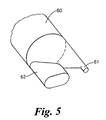
- Figure 5 is an isometric view of a second moulding core used to produce a housing according to the invention.
-
- Figure 1 shows a master cylinder of the type described which is designated generally as 1. The
master cylinder 1, which may form part of an hydraulic system for the operation of a vehicle clutch, comprises a plastics housing 2 produced using injection moulding techniques. The housing 2 defines a bore 3 in which a piston 4 is slideable so as to pressurise fluid in a workingchamber 6 of the bore 3 ahead of the main piston seal 5 for the supply of pressurised fluid to anoutlet 10. The housing has two inlet openings into thebore 7, 8. The first inlet opening 7 is provided for recuperation of fluid from an associated reservoir (not shown) into theworking chamber 6 when the piston 4 is in a retracted position as shown in Figures 1 to 3. The second inlet opening 8 is in permanent communication with asecondary chamber 11 formed in that part of the bore between the main piston seal 5 and a secondary piston seal 9 behind the main piston seal 5. The details of theinlet openings 7, 8 and the filling and operation of the master cylinder will be discussed in more detail later. - The piston 4 is formed of plastics material and is connected to an operating pedal (not shown) of an automotive vehicle clutch by means of an
operating rod 12. One end of therod 12 is received and held in anylon socket 13 located in arecess 44 formed at the rearward end of the piston 4. The end of therod 12 and thesocket 13 are formed such as to permit pivotal movement of therod 12 relative to thesocket 13. Thesocket 13 is held inrecess 44 by an end cap 14 which is secured to the piston 4 by means of asnap connection 15 or by any other suitable means such as a threaded connection or by welding or adhesive. The secondary piston seal 9 is held in position between the end cap 14 and the piston 4. Aprotective seal 39 locates around the rearward end of the housing 2 and has ahole 40 through which therod 12 passes. - A valve assembly 16 (Figure 3) is provided at the forward end of the piston 4. The valve assembly comprises a
valve body 17 having anelongate portion 18 which is a push fit in ablind bore 19 formed in the forward end of the piston 4. Thevalve body 17 has a largerdiameter shoulder portion 20 which holds the main piston seal 5 in position against the piston 4. Thevalve body 17 has astepped bore 21 formed therethrough comprising threesections third sections 23, 24 of the stepped bore 21 house avalve 26. Thevalve 26, which may be of plastics or metal, has anelongate section 27 which locates in thesecond section 23 of thestepped bore 21 and awider diameter section 29 which locates in the third section 24 of thestepped bore 21. Partially surrounding thewider diameter section 29 is acover member 46 which is made of rubber or a relatively soft plastics material. Thecover member 46 is located on thewider diameter section 29 by means of anannular groove 47 formed on an inner diameter thereof for co-operation with anannular ridge 48 formed on the outer diameter of thewider diameter section 29. Thecover member 46 is provided with anannular ridge 25 on a rearward end face. Theridge 25 seals on a forward face 49 formed between the second andthird sections 23, 24 of the stepped bore 21 when thevalve 26 is in a closed position. - The
valve 26 is urged to the closed position by aspring 30. One end of thespring 30 engages anannular shoulder 31 formed on thecover member 46. The other end of thespring 30 is located on anannular shoulder 32 on the rearward face of acap member 33 attached to theshoulder portion 20 of thevalve body 17. Thecap member 33 is a snap fit on theshoulder portion 20 of thevalve body 17 and has astepped bore 34 forming a fluid connection between theworking chamber 6 and the stepped bore 21 of thevalve body 17. Thebore 19 in the piston is in fluid connection with thesecondary chamber 11 by means of one or moreradial bores 35 formed at the closed rearward end of thepiston bore 19. - It should be noted that other means of attaching the
cap member 33 to theshoulder portion 20 of thevalve seat member 17 could be employed. For example a threaded connection could be used or thecap member 33 could be welded or stuck to theshoulder portion 20 using adhesive. - The main piston seal 5 (shown in more detail in Figure 2) comprises a
plastics seal element 36 having asurface 50 which is urged into contact with the bore 3 of the housing 2 by anelastomeric insert 37 located in arecess 38 in theseal element 36. In an alternative embodiment, not shown, theseal element 36 is formed integrally with the piston. Seals of the type in which a plastics sealing element is radially outwardly biased into contact with a bore by a resilient insert are disclosed and clamed in the applicants European patent application No: 98116504.6 to which the reader is referred if more details are required. The precise form of seal, however, is not essential to the invention and any other suitable form of seal may be used. - The
housing outlet 10 is in fluid connection with theworking chamber 6 and comprises aquick fit connector 28 for connection with a conduit (not shown) which conduit interconnects themaster cylinder 1 with the remainder of the hydraulic actuation system which might for example comprise a clutch slave cylinder (not shown). In Figure 1 aprotective cap 45 is shown covering the outlet. Thiscap 45 is used to prevent ingress of contaminants into themaster cylinder 1 prior to the cylinder being fitted on a vehicle and connected to a conduit. - An
external inlet connection 41, for connection with an associated reservoir (not shown) via aconduit 41 a, is formed integrally with the housing 2. The inlet connection has apassage 42 and first andsecond inlet openings 7, 8 which open into the bore 3. The associated reservoir may be shared between the hydraulic system of which themaster cylinder 1 is part and another hydraulic system on the same vehicle. For example the reservoir might serve both the clutch hydraulic system and the brake hydraulic system. Alternatively, the reservoir might solely be associated with the clutch system. - The
inlet openings 7, 8 are shown in more detail in Figure 3. The first inlet opening 7 is formed towards the forward edge of theinlet passage 42, whilst thesecond inlet opening 8 is formed towards a rearward edge of theinlet passage 42. The longitudinal axis X of thepassage 42 is generally parallel with the walls of the first and second inlet openings or the walls of the openings taper inwardly towards the bore 3. Furthermore, the first and second inlet openings are formed in an area within thepassage 42. Thus, in accordance with the invention, its is possible to form theinlet passage 42 and the first andsecond inlet openings 7, 8 in an injection moulding process using asingle moulding core 60 typically of the form shown in Figure 5 in whichcore projections form openings 7 and 8 respectively. As can be seen from Figure 4, the second inlet opening 8 is larger than the first inlet opening 7 and is elongate in shape along an axis parallel to the longitudinal axis of the master cylinder bore 3. - The
master cylinder 1 is mounted to the bulkhead of a motor vehicle (not shown) by means offormations 43 formed on the external surface of the housing 2. - Filling of the
master cylinder 1 will now be described. - The
master cylinder 1 of the described embodiment is supplied and fitted to the motor vehicle in a dry condition. That is to say it is not pre-filled with hydraulic fluid. Once fitted to the vehicle and connected to the remainder of the hydraulic system it is necessary to fill the system with hydraulic fluid. When filling the system the piston 4 must be in the fully retracted position as shown in Figures 1 to 3. This equates to the clutch engaged position when themaster cylinder 1 forms part of a clutch hydraulic actuation system. - With the piston 4 in the fully retracted position, the main piston seal 5 locates on the piston bore 3 at a position between the first and
second inlet openings 7, 8. With the seal in this position, the first inlet opening 7 is in fluid connection with the workingchamber 6 whilst thesecond fluid opening 8 is in fluid connection with thesecondary chamber 11. A vacuum is initially applied toinlet passage 42 to draw air out ofchamber 6 via opening 7 and out ofchamber 11 viaopening 8. - After air evacuation hydraulic fluid is introduced into the system under pressure via the
inlet passage 42. Some of this fluid will enter directly into the workingchamber 6 via the first inlet opening 7. However, most of the fluid will pass through the larger second inlet opening 8 into thesecondary chamber 11. The hydraulic fluid passes from thesecondary chamber 11 through the radial bores 35 into thebore 19 of the piston 4 and from there through the first andsecond sections valve body 17. The fluid in thesecond section 23 of the stepped bore 21 acts on the rearward face of thewider diameter section 29 of thevalve 26 and the pressure of the fluid is sufficient to overcome the closing force of thespring 30 and lifts thevalve 26 off its seat. This allows the fluid to pass through the third section 24 of the stepped bore 21 around thevalve 26 and through the stepped bore 34 of thecap member 33 and into the workingchamber 6. From the workingchamber 6 the fluid passes through theoutlet 10 and via the conduit to the rest of the hydraulic system, for example a clutch slave cylinder from where any air in the system will be bled. Once the hydraulic system is full of hydraulic fluid and all air has been bled, the filling process is complete. - The operation of the
master cylinder 1 will now be described. - With the piston 4 in the fully retracted or clutch disengaged position, as shown in Figures 1 to 3, the main piston seal 5 will, as has already been described above, adopt a position between the first and
second inlet openings 7, 8. When a vehicle operator wishes to disengage the clutch he will depress the clutch pedal in the vehicle which will cause the operatingrod 12 to move forwards in a direction to the right as seen in Figure 1, moving the piston 4 forwardly also. As the piston 4 moves forward the main piston seal 5 will pass over the first inlet opening 7 allowing pressure to be built up in the fluid in the workingchamber 6. As the piston continues to move forwardly pressurised fluid is delivered through theoutlet 10 and via the conduit (not shown) to the clutch slave cylinder (not shown). During this phase, the first andsecond inlet openings 7, 8 are in fluid connection with thesecondary chamber 11 permitting hydraulic fluid to pass between thesecondary chamber 11 and the associated reservoir through theinlet passage 42. Thevalve 26 in the piston 4 is held closed by thespring 30 and by the pressure of the fluid in the workingchamber 6. - Once the operator removes actuation pressure from the operating
rod 12, return pressure in the workingchamber 6 generated as a result of clutch return forces acting on the slave cylinder acts to move the piston rearwardly, to the left as viewed in Figure 1. Again, during this phase fluid is able to pass between thesecondary chamber 11 and the associated reservoir through the second inlet opening 8 and theinlet passage 42. Once the piston 4 has returned to the fully retracted position, the first inlet opening 7 is in fluid connection with the workingchamber 6 allowing fluid to pass into the working chamber to make up for any losses which may have occurred.
Claims (4)
- An injection moulded master cylinder (1) having a housing (2) with a bore (3) in which a piston (4) is slideable to pressurise fluid ahead of a main seal (5) on the piston for the supply of pressurised fluid to an outlet (10), an inlet connection (41) for connection via a conduit (41 a) with a remote reservoir not supported on the master cylinder, the inlet connection opening into the bore via two inlet openings (7,8), a first opening (7) for recuperation of fluid from an associated reservoir to that part of the bore ahead of the main piston seal (5) when the piston (4) is in a retracted position and a second opening (8) placing that portion of the bore between the main piston seal (5) and a second piston seal (9) behind the main seal in permanent communication with the reservoir, the master cylinder being characterised in that the inlet connection comprises an elongate pipe (41) which is integrally moulded at an inner end onto the exterior of the housing (2) at a location surrounding the two inlet openings (7,8) and has an outer end for direct connection with the conduit (41a), the elongate pipe having an elongate smooth internal passage (42) which is moulded simultaneously with the first and second inlet openings (7,8) by a single moulding core (60,61,62).
- A master cylinder as claimed in claim 1 wherein the second inlet opening (8) is larger than the first inlet opening (7).
- A master cylinder as claimed in claim 2, wherein the second inlet opening (8) is elongate in shape along an axis substantially parallel to the longitudinal axis of the housing (2).
- A method of injection moulding a housing for a master cylinder as claimed in claim 1, the method being characterised by comprising the steps of:-injecting plastics material into a mould defining the external shape of the housing including an elongate external inlet pipe connection with an outer end for direct connection with a conduit connected with the remote reservoir, said mould having a first core means defining the housing bore and a second core means defining the elongate smooth internal passage of the elongate inlet pipe and the first and second inlet openings;curing the plastics in the mould;removing said first and second core means; and,removing said moulded housing from said mould.
Applications Claiming Priority (2)
| Application Number | Priority Date | Filing Date | Title |
|---|---|---|---|
| GB9909277 | 1999-04-23 | ||
| GB9909277A GB2349187B (en) | 1999-04-23 | 1999-04-23 | Hydraulic cylinders |
Publications (3)
| Publication Number | Publication Date |
|---|---|
| EP1046561A2 EP1046561A2 (en) | 2000-10-25 |
| EP1046561A3 EP1046561A3 (en) | 2002-07-31 |
| EP1046561B1 true EP1046561B1 (en) | 2005-02-23 |
Family
ID=10852069
Family Applications (1)
| Application Number | Title | Priority Date | Filing Date |
|---|---|---|---|
| EP00105990A Expired - Lifetime EP1046561B1 (en) | 1999-04-23 | 2000-03-27 | Hydraulic cylinders |
Country Status (6)
| Country | Link |
|---|---|
| US (1) | US6460336B1 (en) |
| EP (1) | EP1046561B1 (en) |
| CN (1) | CN1271820A (en) |
| BR (1) | BR0001749A (en) |
| DE (1) | DE60018230T2 (en) |
| GB (1) | GB2349187B (en) |
Families Citing this family (1)
| Publication number | Priority date | Publication date | Assignee | Title |
|---|---|---|---|---|
| DE602004003261T2 (en) * | 2003-01-06 | 2007-05-31 | Nissin Kogyo Co. Ltd., Ueda | Hydraulic master cylinder for a vehicle |
Citations (1)
| Publication number | Priority date | Publication date | Assignee | Title |
|---|---|---|---|---|
| US4566276A (en) * | 1983-03-15 | 1986-01-28 | Aisin Seiki Kabushiki Kaisha | Inlet assembly for a brake master cylinder |
Family Cites Families (12)
| Publication number | Priority date | Publication date | Assignee | Title |
|---|---|---|---|---|
| US3141303A (en) * | 1961-01-11 | 1964-07-21 | Fiat Spa | Master cylinders for hydraulic transmission systems |
| US3412556A (en) * | 1966-10-10 | 1968-11-26 | Gen Motors Corp | Master cylinder assembly |
| US4122596A (en) * | 1977-10-05 | 1978-10-31 | Ford Motor Company | Magnesium die-cast brake master cylinder |
| JPS5544817A (en) * | 1978-09-25 | 1980-03-29 | Aisin Seiki Co Ltd | Method for molding hydrauric cylinder |
| DE3111411A1 (en) * | 1981-03-24 | 1982-10-07 | FAG Kugelfischer Georg Schäfer & Co, 8720 Schweinfurt | TRAINING A MASTER CYLINDER FOR HYDRAULIC BRAKE OR CLUTCH SYSTEMS |
| GB2123910B (en) * | 1982-07-21 | 1985-06-05 | Gen Motors France | Sealing hydraulic brake master cylinder assemblies |
| JPH069839B2 (en) * | 1986-04-28 | 1994-02-09 | 株式会社ナブコ | Manufacturing method of resin cylinder body |
| GB8625523D0 (en) * | 1986-10-24 | 1986-11-26 | Lucas Ind Plc | Pressure cylinder |
| US4959188A (en) * | 1988-04-04 | 1990-09-25 | Automotive Products Plc | Method for forming a hydraulic cylinder assembly |
| US4914916A (en) * | 1988-04-04 | 1990-04-10 | Automotive Products Plc | Tandem master cylinder with electromagnetic position sensors for each piston |
| US5535590A (en) * | 1995-04-06 | 1996-07-16 | General Motors Corporation | Master cylinder with applied brake compensation capability |
| US5720170A (en) * | 1996-07-22 | 1998-02-24 | General Motors Corporation | Master cylinder and emulator with apply assist |
-
1999
- 1999-04-23 GB GB9909277A patent/GB2349187B/en not_active Expired - Fee Related
-
2000
- 2000-03-27 EP EP00105990A patent/EP1046561B1/en not_active Expired - Lifetime
- 2000-03-27 DE DE60018230T patent/DE60018230T2/en not_active Expired - Lifetime
- 2000-04-21 CN CN00106938.1A patent/CN1271820A/en active Pending
- 2000-04-21 US US09/557,887 patent/US6460336B1/en not_active Expired - Fee Related
- 2000-04-24 BR BR0001749-3A patent/BR0001749A/en not_active IP Right Cessation
Patent Citations (1)
| Publication number | Priority date | Publication date | Assignee | Title |
|---|---|---|---|---|
| US4566276A (en) * | 1983-03-15 | 1986-01-28 | Aisin Seiki Kabushiki Kaisha | Inlet assembly for a brake master cylinder |
Also Published As
| Publication number | Publication date |
|---|---|
| DE60018230D1 (en) | 2005-03-31 |
| US6460336B1 (en) | 2002-10-08 |
| BR0001749A (en) | 2000-10-31 |
| EP1046561A3 (en) | 2002-07-31 |
| DE60018230T2 (en) | 2005-12-29 |
| GB9909277D0 (en) | 1999-06-16 |
| GB2349187A (en) | 2000-10-25 |
| CN1271820A (en) | 2000-11-01 |
| EP1046561A2 (en) | 2000-10-25 |
| GB2349187B (en) | 2003-09-17 |
Similar Documents
| Publication | Publication Date | Title |
|---|---|---|
| CA2273593C (en) | Farm coupling | |
| GB2211567A (en) | Tandem master cylinder for hydraulic brake systems of automotive vehicles | |
| WO1987003344A1 (en) | Fluid pressure system and actuator therefor | |
| US6418717B1 (en) | Hydraulic cylinders | |
| EP0072745B1 (en) | Braking apparatus for automotive vehicles | |
| US6460336B1 (en) | Hydraulic cylinders | |
| JP2001509452A (en) | Sensor assembly for brake booster and brake booster having the same | |
| US9027340B2 (en) | Brake booster for an automotive brake system and corresponding automotive brake system | |
| EP0519533B1 (en) | Master cylinder and end fitting therefor | |
| EP0221807B1 (en) | Hydraulic brake booster with quick take-up and full stroke | |
| AU3667599A (en) | Concentric compensator chamber and master cylinder for disc brake system | |
| EP0843790B1 (en) | Modular master cylinder construction | |
| EP0252701A2 (en) | Master cylinder | |
| EP1306562B1 (en) | Hydraulic actuator with retainer | |
| EP1058043B1 (en) | Farm coupling | |
| FR2586983A1 (en) | SLIDING REGULATION BRAKING SYSTEM | |
| JPH09500072A (en) | Brake device master cylinder and brake booster structure | |
| US4856416A (en) | Hydraulic cylinder structure | |
| US6851767B2 (en) | Actuator for an electrohydraulic braking system | |
| US4121421A (en) | Hydraulic brake booster having charging and check valves | |
| EP1451481B1 (en) | Actuator | |
| US7121094B2 (en) | Center valve for master cylinder | |
| KR970003892Y1 (en) | Master cylinder of hydraulic clutch | |
| US20040148929A1 (en) | Master cylinder device with booster device | |
| JP4699439B2 (en) | Master cylinder |
Legal Events
| Date | Code | Title | Description |
|---|---|---|---|
| PUAI | Public reference made under article 153(3) epc to a published international application that has entered the european phase |
Free format text: ORIGINAL CODE: 0009012 |
|
| AK | Designated contracting states |
Kind code of ref document: A2 Designated state(s): AT BE CH CY DE DK ES FI FR GB GR IE IT LI LU MC NL PT SE |
|
| AX | Request for extension of the european patent |
Free format text: AL;LT;LV;MK;RO;SI |
|
| PUAL | Search report despatched |
Free format text: ORIGINAL CODE: 0009013 |
|
| AK | Designated contracting states |
Kind code of ref document: A3 Designated state(s): AT BE CH CY DE DK ES FI FR GB GR IE IT LI LU MC NL PT SE |
|
| AX | Request for extension of the european patent |
Free format text: AL;LT;LV;MK;RO;SI |
|
| 17P | Request for examination filed |
Effective date: 20021213 |
|
| AKX | Designation fees paid |
Designated state(s): DE FR GB IT |
|
| 17Q | First examination report despatched |
Effective date: 20031202 |
|
| GRAP | Despatch of communication of intention to grant a patent |
Free format text: ORIGINAL CODE: EPIDOSNIGR1 |
|
| GRAS | Grant fee paid |
Free format text: ORIGINAL CODE: EPIDOSNIGR3 |
|
| GRAA | (expected) grant |
Free format text: ORIGINAL CODE: 0009210 |
|
| AK | Designated contracting states |
Kind code of ref document: B1 Designated state(s): DE FR GB IT |
|
| PG25 | Lapsed in a contracting state [announced via postgrant information from national office to epo] |
Ref country code: IT Free format text: LAPSE BECAUSE OF FAILURE TO SUBMIT A TRANSLATION OF THE DESCRIPTION OR TO PAY THE FEE WITHIN THE PRESCRIBED TIME-LIMIT;WARNING: LAPSES OF ITALIAN PATENTS WITH EFFECTIVE DATE BEFORE 2007 MAY HAVE OCCURRED AT ANY TIME BEFORE 2007. THE CORRECT EFFECTIVE DATE MAY BE DIFFERENT FROM THE ONE RECORDED. Effective date: 20050223 |
|
| REG | Reference to a national code |
Ref country code: GB Ref legal event code: FG4D |
|
| RIN1 | Information on inventor provided before grant (corrected) |
Inventor name: DESBOIS, PATRICK Inventor name: THENAULT, YANNICK |
|
| REG | Reference to a national code |
Ref country code: IE Ref legal event code: FG4D |
|
| REF | Corresponds to: |
Ref document number: 60018230 Country of ref document: DE Date of ref document: 20050331 Kind code of ref document: P |
|
| PLBE | No opposition filed within time limit |
Free format text: ORIGINAL CODE: 0009261 |
|
| STAA | Information on the status of an ep patent application or granted ep patent |
Free format text: STATUS: NO OPPOSITION FILED WITHIN TIME LIMIT |
|
| 26N | No opposition filed |
Effective date: 20051124 |
|
| ET | Fr: translation filed | ||
| GBPC | Gb: european patent ceased through non-payment of renewal fee |
Effective date: 20070327 |
|
| PG25 | Lapsed in a contracting state [announced via postgrant information from national office to epo] |
Ref country code: GB Free format text: LAPSE BECAUSE OF NON-PAYMENT OF DUE FEES Effective date: 20070327 |
|
| PGFP | Annual fee paid to national office [announced via postgrant information from national office to epo] |
Ref country code: GB Payment date: 20060322 Year of fee payment: 7 |
|
| PGFP | Annual fee paid to national office [announced via postgrant information from national office to epo] |
Ref country code: FR Payment date: 20080319 Year of fee payment: 9 |
|
| REG | Reference to a national code |
Ref country code: FR Ref legal event code: ST Effective date: 20091130 |
|
| PG25 | Lapsed in a contracting state [announced via postgrant information from national office to epo] |
Ref country code: FR Free format text: LAPSE BECAUSE OF NON-PAYMENT OF DUE FEES Effective date: 20091123 |
|
| REG | Reference to a national code |
Ref country code: DE Ref legal event code: R081 Ref document number: 60018230 Country of ref document: DE Owner name: SCHAEFFLER TECHNOLOGIES AG & CO. KG, DE Free format text: FORMER OWNER: SCHAEFFLER TECHNOLOGIES GMBH & CO. KG, 91074 HERZOGENAURACH, DE Effective date: 20120828 Ref country code: DE Ref legal event code: R081 Ref document number: 60018230 Country of ref document: DE Owner name: SCHAEFFLER TECHNOLOGIES GMBH & CO. KG, DE Free format text: FORMER OWNER: SCHAEFFLER TECHNOLOGIES GMBH & CO. KG, 91074 HERZOGENAURACH, DE Effective date: 20120828 |
|
| REG | Reference to a national code |
Ref country code: DE Ref legal event code: R081 Ref document number: 60018230 Country of ref document: DE Owner name: SCHAEFFLER TECHNOLOGIES GMBH & CO. KG, DE Free format text: FORMER OWNER: SCHAEFFLER TECHNOLOGIES AG & CO. KG, 91074 HERZOGENAURACH, DE Effective date: 20140218 Ref country code: DE Ref legal event code: R081 Ref document number: 60018230 Country of ref document: DE Owner name: SCHAEFFLER TECHNOLOGIES AG & CO. KG, DE Free format text: FORMER OWNER: SCHAEFFLER TECHNOLOGIES AG & CO. KG, 91074 HERZOGENAURACH, DE Effective date: 20140218 |
|
| REG | Reference to a national code |
Ref country code: DE Ref legal event code: R081 Ref document number: 60018230 Country of ref document: DE Owner name: SCHAEFFLER TECHNOLOGIES AG & CO. KG, DE Free format text: FORMER OWNER: SCHAEFFLER TECHNOLOGIES GMBH & CO. KG, 91074 HERZOGENAURACH, DE Effective date: 20150210 |
|
| PGFP | Annual fee paid to national office [announced via postgrant information from national office to epo] |
Ref country code: DE Payment date: 20190528 Year of fee payment: 20 |
|
| REG | Reference to a national code |
Ref country code: DE Ref legal event code: R071 Ref document number: 60018230 Country of ref document: DE |
|
| P01 | Opt-out of the competence of the unified patent court (upc) registered |
Effective date: 20230523 |