EP1045956B1 - A locking device for roller blinds - Google Patents
A locking device for roller blinds Download PDFInfo
- Publication number
- EP1045956B1 EP1045956B1 EP99900445A EP99900445A EP1045956B1 EP 1045956 B1 EP1045956 B1 EP 1045956B1 EP 99900445 A EP99900445 A EP 99900445A EP 99900445 A EP99900445 A EP 99900445A EP 1045956 B1 EP1045956 B1 EP 1045956B1
- Authority
- EP
- European Patent Office
- Prior art keywords
- depressions
- balls
- ball
- shaft
- radial depressions
- Prior art date
- Legal status (The legal status is an assumption and is not a legal conclusion. Google has not performed a legal analysis and makes no representation as to the accuracy of the status listed.)
- Expired - Lifetime
Links
- 238000010276 construction Methods 0.000 description 8
- 230000000903 blocking effect Effects 0.000 description 3
- 230000005484 gravity Effects 0.000 description 3
- 230000002787 reinforcement Effects 0.000 description 3
- 230000001419 dependent effect Effects 0.000 description 2
- 230000001133 acceleration Effects 0.000 description 1
- 230000009286 beneficial effect Effects 0.000 description 1
- 239000000428 dust Substances 0.000 description 1
- 230000000694 effects Effects 0.000 description 1
- 238000004519 manufacturing process Methods 0.000 description 1
- 238000000034 method Methods 0.000 description 1
- 239000007787 solid Substances 0.000 description 1
Images
Classifications
-
- E—FIXED CONSTRUCTIONS
- E06—DOORS, WINDOWS, SHUTTERS, OR ROLLER BLINDS IN GENERAL; LADDERS
- E06B—FIXED OR MOVABLE CLOSURES FOR OPENINGS IN BUILDINGS, VEHICLES, FENCES OR LIKE ENCLOSURES IN GENERAL, e.g. DOORS, WINDOWS, BLINDS, GATES
- E06B9/00—Screening or protective devices for wall or similar openings, with or without operating or securing mechanisms; Closures of similar construction
- E06B9/56—Operating, guiding or securing devices or arrangements for roll-type closures; Spring drums; Tape drums; Counterweighting arrangements therefor
- E06B9/80—Safety measures against dropping or unauthorised opening; Braking or immobilising devices; Devices for limiting unrolling
- E06B9/82—Safety measures against dropping or unauthorised opening; Braking or immobilising devices; Devices for limiting unrolling automatic
- E06B9/90—Safety measures against dropping or unauthorised opening; Braking or immobilising devices; Devices for limiting unrolling automatic for immobilising the closure member in various chosen positions
Definitions
- the invention relates to a locking mechanism for roller blinds comprising a non-rotating shaft with a first set of radial depressions having inclined surfaces and an intermittently rotating drum with a second set of radial depressions mounted in a spring driven roller blind tube and provided with balls adapted for providing an interlocking of the shaft and the drum by jamming between said first and second set of depressions.
- This type of locking of a roller blind replaced a construction using ratchets and ratchet wheels which permitted the pulling of the roller blind during tightening of the spring fitted inside the tube and locking.
- the ratchets were mounted on journals on the drum, and by sufficiently rapid rotation they were flung outwards and held at a distance from the ratchet wheel. During slow rotation gravity caused re-engagement.
- the construction using ratchets caused expensive manufacture of ratchets and ratchet wheels and the wear and friction on the bearings of the ratchets were replaced by balls which established locking between the stationary shaft and the drum by falling into the radial depressions in the stationary shaft.
- this advantageous construction gives problems, if the stationary shaft cannot be securely placed in a position so that one of the two first depressions is upwards turned (and consequently the other is facing downwards). When such a depression faces upwards, three lockings are ensured per revolution, whereas if the two first depressions are facing sideways (i.e. at right angles to the first position described above), then coincidences will determine if a ball rolls into the space between the shaft and drum and creates a locking thereby.
- This has the effect that the known, otherwise useful construction does not have the freedom of orientation which is required by modern building techniques. It is required that a roller blind tube can be mounted in their mountings, irrespective of whether they are mounted on a wall or in the ceiling, and hence 4 depressions in the shaft are required in practice.
- Modern locking devices are disposed such that the balls obtain a free run towards the centre of the shaft. This means that the moment the component of gravity is larger than the component of the centripetal acceleration the ball will roll towards the centre of the shaft and thereby lock the drum. Thereby the rotational velocity which must be overcome is only dependent on the distance of the ball from the centre of rotation and by the rotational velocity for a fixed placement of the locking depressions in the shaft. This means that the spring must be tightened to such a degree that the necessary rotational velocity will be obtained at the latest after 1/3 revolution, in order that the mechanism is released and the roller blind moved upwards. This requires a large tightening of the spring and causes the roller blind to move upwards at high velocity.
- the second set of radial depressions is provided with protusions in the direction of rolling-up as a partial support for the balls and in order to create a release direction for the balls which is not directed towards the centre of rotation.
- protusions in the direction of rolling-up as a partial support for the balls and in order to create a release direction for the balls which is not directed towards the centre of rotation.
- the invention is particular in that surfaces have been provided at the second set of radial depressions such that the jamming of a ball occurs with a force which is directed at an angle with respect to the tangent to the shaft at the ball in question.
- Another way of expressing this is that the inclined surfaces are oriented differently from the usual where the force is essentially directed tangentially.
- the increased radial force is no disadvantage, and the advantage of the inclined surfaces is furthermore that the balls may "roll" from the second set of radial depressions whithout being dependent on a purely radial movement.
- the bottoms of the second set of radial depressions are shaped as a part of a spherical surface with a radius essentially equal to the radius of the balls.
- Such spherical surfaces are disposed in the bottom on either side of the protrusions, so that the balls are not only jammed between edges on the first and second set of depressions, but are also supported by a part of a spherical surface.
- the protrusions in the second set of radial depressions are reinforced by the spherical transfer to the bottom, and the strenght increases. Thereby a greater security is obtained against deformation and wear.
- a further embodiment is particular in that also the first set of radial depressions are provided with bottoms which are parts of spherical surfaces with a radius essentially equal to the radius of the balls. This enables a less solid construction of the walls between the axial depressions (first set of radial depressions) in the shaft, whereby more depressions may be fitted for a given axial diameter.
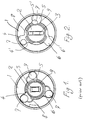
- Fig. 1 a blocking mechanism according to the prior art where a drum 1 with a bearing which is not shown is fitted rotatably around a stationary shaft 2.
- the shaft is provided with a profile 3 at the end which may lock against rotation to the support bracket.
- the drum is provided with 3 radial depressions 4, 5, 6 which are capable of containing balls 7 such that they do not engage the depressions 8, 9 in the shaft 2.
- This condition is maintained as long as the balls are flung outwards with sufficient force, and it is this condition which is shown in the figure.
- the surface which during rotation presses against the ball is directed towards the centre of the movement.
- the borderline case obtains when a depression 4, 5, 6 with a ball is directly above the shaft, while the sides of the depression contributes to holding the balls in other angular positions.
- a ball falls down to touch a depression 8, 9 it jams between the slanted surfaces, and blocking occurs.
- Fig. 2 is seen an embodiment of the invention in which the depressions 4, 5, 6 are differently shaped, in that there are provided protrusions 4', 5', 6' which partly support the ball which is at any time the topmost ball, even during slow rotation.
- the shaft is provided with the depressions 8, 9, 10, 11.
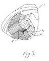
- Fig. 3 is seen the shape of one of the depressions in the second set of radial depressions in perspective detail.
- the edge or protrusion 4' is seen between the depression with the greatest radial distance to the centre 4 and the depression 4" which is to cooperate with a ball 7 and one of the first set of depressions 8, 9 on the stationary shaft 2.
- the bottom of the depressions in the drum 1 is given a spherical shape, i.e. the depressions have a spherical surface as the transfer to a plane perpendicular to the axis of the drum.
Landscapes
- Engineering & Computer Science (AREA)
- Structural Engineering (AREA)
- Architecture (AREA)
- Civil Engineering (AREA)
- Pivots And Pivotal Connections (AREA)
- Blinds (AREA)
Description
- The invention relates to a locking mechanism for roller blinds comprising a non-rotating shaft with a first set of radial depressions having inclined surfaces and an intermittently rotating drum with a second set of radial depressions mounted in a spring driven roller blind tube and provided with balls adapted for providing an interlocking of the shaft and the drum by jamming between said first and second set of depressions.
- This type of locking of a roller blind replaced a construction using ratchets and ratchet wheels which permitted the pulling of the roller blind during tightening of the spring fitted inside the tube and locking. The ratchets were mounted on journals on the drum, and by sufficiently rapid rotation they were flung outwards and held at a distance from the ratchet wheel. During slow rotation gravity caused re-engagement. The construction using ratchets caused expensive manufacture of ratchets and ratchet wheels and the wear and friction on the bearings of the ratchets were replaced by balls which established locking between the stationary shaft and the drum by falling into the radial depressions in the stationary shaft. Due to the small diameter of a roller blind tube and the need for a suitable mass for the balls, so that they can overcome possible dust and still provide a reliable movement, fairly large balls have been used and only two first radial depressions which cooperate with three second radial depressions. This provides for sufficient possibilities of locking in practice.
- However, in particular this advantageous construction gives problems, if the stationary shaft cannot be securely placed in a position so that one of the two first depressions is upwards turned (and consequently the other is facing downwards). When such a depression faces upwards, three lockings are ensured per revolution, whereas if the two first depressions are facing sideways (i.e. at right angles to the first position described above), then coincidences will determine if a ball rolls into the space between the shaft and drum and creates a locking thereby. This has the effect that the known, otherwise useful construction does not have the freedom of orientation which is required by modern building techniques. It is required that a roller blind tube can be mounted in their mountings, irrespective of whether they are mounted on a wall or in the ceiling, and hence 4 depressions in the shaft are required in practice.
- Modern locking devices are disposed such that the balls obtain a free run towards the centre of the shaft. This means that the moment the component of gravity is larger than the component of the centripetal acceleration the ball will roll towards the centre of the shaft and thereby lock the drum. Thereby the rotational velocity which must be overcome is only dependent on the distance of the ball from the centre of rotation and by the rotational velocity for a fixed placement of the locking depressions in the shaft. This means that the spring must be tightened to such a degree that the necessary rotational velocity will be obtained at the latest after 1/3 revolution, in order that the mechanism is released and the roller blind moved upwards. This requires a large tightening of the spring and causes the roller blind to move upwards at high velocity.
- A construction that displays the above features may be found in US 4,345,636 which describes a stationary shaft having two first radial depressions cooperating with a drum having four second radial depressions via two balls.
- An example of a set of balls and depressions for use in a roller blind will be found in EP 0419 017 A2, in which the depressions have been given a special shape to provide a different velocity development, albeit in connection with a ratchet controlled by the jamming of the balls.
- It is the purpose of the invention to avoid these disadvantages, and this is obtained in that the second set of radial depressions is provided with protusions in the direction of rolling-up as a partial support for the balls and in order to create a release direction for the balls which is not directed towards the centre of rotation. Thereby "pockets" are so to speak created in the drum for the balls which support the balls partly, so that a part of the force with which gravity influences the ball which is at any one instant the top one, is taken up by the drum. Hereby the force which forces the ball against the locking surface on the shaft is reduced. In this manner a reduction of the rotational speed which is required to keep the balls in the drum is obtained. Thereby the spring does not need to be tightened as in the prior art, and the roller blind may move much slower before the ball is locked. Thereby a given spring mechanism obtains a larger capacity and may be used for larger roller blinds than in known constructions.
- The invention is particular in that surfaces have been provided at the second set of radial depressions such that the jamming of a ball occurs with a force which is directed at an angle with respect to the tangent to the shaft at the ball in question. Another way of expressing this is that the inclined surfaces are oriented differently from the usual where the force is essentially directed tangentially. The increased radial force is no disadvantage, and the advantage of the inclined surfaces is furthermore that the balls may "roll" from the second set of radial depressions whithout being dependent on a purely radial movement. Hereby it becomes possible under certain circumstances to provide only two first radial depressions.
- Furthermore the bottoms of the second set of radial depressions are shaped as a part of a spherical surface with a radius essentially equal to the radius of the balls. Such spherical surfaces are disposed in the bottom on either side of the protrusions, so that the balls are not only jammed between edges on the first and second set of depressions, but are also supported by a part of a spherical surface. The protrusions in the second set of radial depressions are reinforced by the spherical transfer to the bottom, and the strenght increases. Thereby a greater security is obtained against deformation and wear.
- A further embodiment is particular in that also the first set of radial depressions are provided with bottoms which are parts of spherical surfaces with a radius essentially equal to the radius of the balls. This enables a less solid construction of the walls between the axial depressions (first set of radial depressions) in the shaft, whereby more depressions may be fitted for a given axial diameter.
- The invention will be described in greater detail in the following with reference to the drawing, in which
-
Fig. 1 shows a known construction in cross section through the balls and depressions, -
Fig. 2 shows an embodiment of the invention, and -
Fig. 3 shows an embodiment with a reinforcement of the protrusions. - In
Fig. 1 is shown a blocking mechanism according to the prior art where a drum 1 with a bearing which is not shown is fitted rotatably around astationary shaft 2. The shaft is provided with aprofile 3 at the end which may lock against rotation to the support bracket. The drum is provided with 3radial depressions balls 7 such that they do not engage thedepressions shaft 2. During rotation this condition is maintained as long as the balls are flung outwards with sufficient force, and it is this condition which is shown in the figure. The surface which during rotation presses against the ball is directed towards the centre of the movement. The borderline case obtains when adepression depression - In
Fig. 2 is seen an embodiment of the invention in which thedepressions depressions depression 4 and another ball which performs blocking at thedepression 5, 5'. - In
Fig. 3 is seen the shape of one of the depressions in the second set of radial depressions in perspective detail. Using the same reference numerals as inFig. 2 , the edge or protrusion 4' is seen between the depression with the greatest radial distance to thecentre 4 and thedepression 4" which is to cooperate with aball 7 and one of the first set ofdepressions stationary shaft 2. The bottom of the depressions in the drum 1 is given a spherical shape, i.e. the depressions have a spherical surface as the transfer to a plane perpendicular to the axis of the drum. Compared to the situation where the depressions are constituted as cylindrical surfaces which intersect in the protrusion 4', a reinforcement is obtained of the edge which is created, because it thicker near the bottom while retaining a shape which corresponds to theball 7, namely acircular arc 4c which is seen from the edge inFig. 3 . This reinforcement of the edge has shown itself to have a beneficial influence on the durability of the edge or protrusion. A part of the reason is that there is a surface contact sphere-against-sphere against theball 7 instead of just a circle, as in the case ball against cylinder.
Claims (2)
- A locking mechanism for roller blinds comprising1) a non-rotating shaft (2) with four first radial depressions (8) having inclined surfaces;2) an intermittently rotating drum (1) mounted in a spring driven roller blind tube and with a second set of radial depressions (4, 5, 6);3) balls (7) adapted for providing an interlocking of the shaft and the drum by jamming between said first and second set of depressions;said second set of radial depressions (4, 5, 6) being provided with protrusions (4', 5', 6') in the direction of rolling-up as a partial support for the balls (7) and in order to create a release direction for the balls which is not directed towards the centre of rotation,
said second set of radial depressions (4, 5, 6) being provided with surfaces such that the jamming of a ball (7) occurs with a force which is directed at an angle with respect to the tangent to the shaft at the ball in question,
characterised in that the bottoms of the second set of radial depressions (4, 5, 6) are shaped as a part of a spherical surface with a radius essentially equal to the radius of the balls (7). - A locking mechanism according to claim 1,
characterised in that also the radial depressions (8) in the first set are provided with bottoms which are parts of spherical surfaces with a radius essentially equal to the radius of the balls (7).
Applications Claiming Priority (3)
| Application Number | Priority Date | Filing Date | Title |
|---|---|---|---|
| DK1998A DK1998A (en) | 1998-01-09 | 1998-01-09 | Shut-off alignment mechanism |
| DK1998 | 1998-09-24 | ||
| PCT/DK1999/000015 WO1999037876A1 (en) | 1998-01-09 | 1999-01-11 | A locking device for roller blinds |
Publications (2)
| Publication Number | Publication Date |
|---|---|
| EP1045956A1 EP1045956A1 (en) | 2000-10-25 |
| EP1045956B1 true EP1045956B1 (en) | 2008-09-03 |
Family
ID=8088834
Family Applications (1)
| Application Number | Title | Priority Date | Filing Date |
|---|---|---|---|
| EP99900445A Expired - Lifetime EP1045956B1 (en) | 1998-01-09 | 1999-01-11 | A locking device for roller blinds |
Country Status (5)
| Country | Link |
|---|---|
| EP (1) | EP1045956B1 (en) |
| AU (1) | AU1960899A (en) |
| DE (1) | DE69939459D1 (en) |
| DK (1) | DK1998A (en) |
| WO (1) | WO1999037876A1 (en) |
Families Citing this family (4)
| Publication number | Priority date | Publication date | Assignee | Title |
|---|---|---|---|---|
| US9963935B2 (en) | 2013-03-15 | 2018-05-08 | Hunter Douglas Inc. | Position lock for roller supported architectural coverings |
| US9322210B2 (en) | 2013-08-19 | 2016-04-26 | Comfortex Window Fashions | Cordless fabric venetian window shade assembly |
| KR101359513B1 (en) | 2013-08-27 | 2014-02-07 | 곽재석 | Dual fabric blind fabric angle adjustment device |
| WO2020180943A1 (en) | 2019-03-06 | 2020-09-10 | Hunter Douglas Inc. | Bottom rail for double panel window shading and method to operate same |
Family Cites Families (6)
| Publication number | Priority date | Publication date | Assignee | Title |
|---|---|---|---|---|
| US953842A (en) * | 1909-05-18 | 1910-04-05 | Achille Kaiserman | Shade-roller. |
| US1019653A (en) * | 1911-03-01 | 1912-03-05 | Achille Kaiserman | Window-shade roller. |
| JPS5520815A (en) * | 1978-07-31 | 1980-02-14 | Metako Kigyo Kk | Rolled screen |
| US5099906A (en) * | 1989-09-19 | 1992-03-31 | Metaco Co., Ltd. | Roller screen unit |
| ITAN940011A1 (en) * | 1994-03-09 | 1995-09-11 | Gaposa Srl | CUSHIONED STOP DEVICE FOR ROLLING SHUTTERS OR SHUTTERS |
| DE19603727A1 (en) * | 1996-02-02 | 1997-08-07 | Mfz Antriebe Gmbh | Safety gear with lightweight ratchet |
-
1998
- 1998-01-09 DK DK1998A patent/DK1998A/en not_active Application Discontinuation
-
1999
- 1999-01-11 EP EP99900445A patent/EP1045956B1/en not_active Expired - Lifetime
- 1999-01-11 DE DE69939459T patent/DE69939459D1/en not_active Expired - Fee Related
- 1999-01-11 WO PCT/DK1999/000015 patent/WO1999037876A1/en not_active Ceased
- 1999-01-11 AU AU19608/99A patent/AU1960899A/en not_active Abandoned
Also Published As
| Publication number | Publication date |
|---|---|
| EP1045956A1 (en) | 2000-10-25 |
| WO1999037876A1 (en) | 1999-07-29 |
| DE69939459D1 (en) | 2008-10-16 |
| AU1960899A (en) | 1999-08-09 |
| DK1998A (en) | 1999-10-01 |
Similar Documents
| Publication | Publication Date | Title |
|---|---|---|
| CA2296176C (en) | Vehicular seatbelt retractor | |
| US6655088B1 (en) | Safety break for an overhead door | |
| CN101631963B (en) | Roller-type one-way clutch | |
| US4346793A (en) | Motion snubbing device | |
| JP3455426B2 (en) | Acceleration sensor | |
| US20040262109A1 (en) | Fall safety device | |
| CN1197401A (en) | Automatic fall protection device for workers working at heights | |
| JP2001159434A (en) | Emergency brake device | |
| WO1999037876A1 (en) | A locking device for roller blinds | |
| JP6215169B2 (en) | Braking device for sliding door | |
| US6065812A (en) | Bicycle wheel rim capable of cooperating with brake shoes to bring about smooth and stable braking action | |
| JP2000107643A (en) | Centrifuge rotor attachment / detachment mechanism | |
| JP2000107643A5 (en) | ||
| JP2005521817A (en) | Safety devices used to operate closures or sunshade equipment and mechanisms comprising such devices | |
| US4871279A (en) | Slalom post | |
| CA1113409A (en) | Anti-reversal device | |
| JP2653766B2 (en) | Inertial sensor for vehicle response triggering of belt retractor lock mechanism | |
| JP2000343989A (en) | Stepless slide adjuster with safe lock | |
| EP0671543B1 (en) | Cushioned locking device for rolling shutters or blinds | |
| NL1010164C2 (en) | Wheel cover assembly. | |
| JP3944513B2 (en) | Building shutter fall prevention device | |
| CN115702114B (en) | Rotary locking device, lever hoist and winch | |
| JP5270818B2 (en) | Fall prevention device for architectural shutter | |
| US5592778A (en) | Safety turnstile | |
| JPH05164154A (en) | Ball clutch having trip torque varying with direction of rotation |
Legal Events
| Date | Code | Title | Description |
|---|---|---|---|
| PUAI | Public reference made under article 153(3) epc to a published international application that has entered the european phase |
Free format text: ORIGINAL CODE: 0009012 |
|
| 17P | Request for examination filed |
Effective date: 20000808 |
|
| AK | Designated contracting states |
Kind code of ref document: A1 Designated state(s): DE DK FR GB NL |
|
| 17Q | First examination report despatched |
Effective date: 20050831 |
|
| GRAP | Despatch of communication of intention to grant a patent |
Free format text: ORIGINAL CODE: EPIDOSNIGR1 |
|
| GRAS | Grant fee paid |
Free format text: ORIGINAL CODE: EPIDOSNIGR3 |
|
| GRAA | (expected) grant |
Free format text: ORIGINAL CODE: 0009210 |
|
| AK | Designated contracting states |
Kind code of ref document: B1 Designated state(s): DE DK FR GB NL |
|
| REG | Reference to a national code |
Ref country code: GB Ref legal event code: FG4D |
|
| REF | Corresponds to: |
Ref document number: 69939459 Country of ref document: DE Date of ref document: 20081016 Kind code of ref document: P |
|
| PG25 | Lapsed in a contracting state [announced via postgrant information from national office to epo] |
Ref country code: NL Free format text: LAPSE BECAUSE OF FAILURE TO SUBMIT A TRANSLATION OF THE DESCRIPTION OR TO PAY THE FEE WITHIN THE PRESCRIBED TIME-LIMIT Effective date: 20080903 |
|
| NLV1 | Nl: lapsed or annulled due to failure to fulfill the requirements of art. 29p and 29m of the patents act | ||
| PLBE | No opposition filed within time limit |
Free format text: ORIGINAL CODE: 0009261 |
|
| STAA | Information on the status of an ep patent application or granted ep patent |
Free format text: STATUS: NO OPPOSITION FILED WITHIN TIME LIMIT |
|
| PG25 | Lapsed in a contracting state [announced via postgrant information from national office to epo] |
Ref country code: DK Free format text: LAPSE BECAUSE OF FAILURE TO SUBMIT A TRANSLATION OF THE DESCRIPTION OR TO PAY THE FEE WITHIN THE PRESCRIBED TIME-LIMIT Effective date: 20080903 |
|
| 26N | No opposition filed |
Effective date: 20090604 |
|
| GBPC | Gb: european patent ceased through non-payment of renewal fee |
Effective date: 20090111 |
|
| PG25 | Lapsed in a contracting state [announced via postgrant information from national office to epo] |
Ref country code: DE Free format text: LAPSE BECAUSE OF NON-PAYMENT OF DUE FEES Effective date: 20090801 |
|
| REG | Reference to a national code |
Ref country code: FR Ref legal event code: ST Effective date: 20091030 |
|
| PG25 | Lapsed in a contracting state [announced via postgrant information from national office to epo] |
Ref country code: GB Free format text: LAPSE BECAUSE OF NON-PAYMENT OF DUE FEES Effective date: 20090111 |
|
| PG25 | Lapsed in a contracting state [announced via postgrant information from national office to epo] |
Ref country code: FR Free format text: LAPSE BECAUSE OF NON-PAYMENT OF DUE FEES Effective date: 20090202 |