CROSS REFERENCES TO RELATED APPLICATIONS
This application claims the benefit of U.S.
Provisional Application 60/129,200, filed 4/14/99.
TECHNICAL FIELD
The present invention relates to a system for and
method of operating a discharge lamp, and more
particularly, to a system and method whereby a
mercury free discharge lamp having improved color,
efficacy and longevity may be operated in any
orientation without change in its electrical
characteristics or light output.
BACKGROUND ART
Metal halide lamps in widespread use today evolved
from pure mercury arc lamps developed early this
century. Mercury is an ideal arc generating medium
because it is a liquid with a low vapor pressure at
room temperature which makes it is relatively easy to
strike and sustain an arc. At lamp operating
temperatures, the mercury pressure becomes quite high
and the voltage across the lamp increases to the
point where cost effective, efficient power supplies
can be used to drive the lamp. Metal halide salts are
added to improve the spectral properties of the
mercury discharge thereby making the metal halide
lamp more efficacious.
The use of mercury in metal halide lamps presents
well known environmental concerns. In response,
industry has attempted to provide mercury free lamps.
However, previous attempts at lighting systems which
include mercury free lamps have presented many
problems. For example, some mercury free lighting
systems have incurred poor efficacy, color and light
characteristics. Moreover, previous mercury free
lamps have been restricted to operating conditions
wherein the lamp must be positioned horizontally. In
particular, the tubular lamps tend to restrict
convection and, consequently, chemical mixing in the
lamp. When operated horizontally, this is not a
problem because the chemicals eventually diffuse
uniformly throughout the lamp. However, when the lamp
operates vertically, gravity causes the chemicals to
collect at the bottom of the lamp. This causes an
undesirable color variation along the length of the
lamp and a temperature non-uniformity that greatly
reduces lamp life. Efforts to improve efficacy and
color have met some success yet such improved mercury
free lamps can only be operated in a horizontal
orientation.
Many efforts have been made to provide a mercury free
lamp which overcomes the foregoing shortcomings. For
example, U.S. patent no. 5,394,057 which issued on 28
February 1995 to Russell et al. illustrates the use
of a protective coating on mercury free metal halide
lamps.
U.S. patent no. 5,363,015 which issued on 08 November
1994 to Dakin et al. relates to a lighting system
which includes an electrodeless mercury free metal
halide lamp. U.S. patent no. 5,479,072 which issued
on 26 December 1995 to Dakin et al. is of similar
interest.
U.S. patent no. 5,523,655 which issued on 04 June
1996 to Jennato et al. illustrates a low pressure
lighting system which includes a mercury free neon
lamp and a pulsed ballast. U.S. patent no. 5,565,741
which issued on 15 October 1996 to Jennato et al.,
and U.S. patent no. 5,666,031 which issued on 09
September 1997 to Jennato et al., are of similar
interest.
Notwithstanding the foregoing efforts it is still
desired to provide an improved lighting system
including a mercury free lamp having photometric
results which exceed those heretofore achieved and
wherein the lamp may be positioned in any desired
orientation. Heretofore, there has been a tendency
to design lamps and lamp ballasts separately. As a
result, when providing lamp systems, such systems
have been optimized individually. The result has
often been less than optimal. For example, designers
of mercury free lamps have not applied acoustic
technology to improve the photometric results of such
lamps. The present invention meets the foregoing
objectives by providing a lighting system which
includes a mercury free metal halide lamp and a
ballast system having acoustic arc conditioning.
The use of acoustics in lighting systems is well
known. For example, in conventional lamp
applications provided heretofore efforts have been
made to acoustically influence the arc to straighten
or otherwise stabilize and center the arc. For
example, U.S. patent no. 5,134,345 issued on 28 July
1992 to El-Hamamsy et al. illustrates a method of
detecting arc instabilities in a High Intensity
Discharge (HID) lamp and changing the drive
frequencies that cause them thereby avoiding acoustic
frequencies that cause destabilizing phenomena.
In U.S. patent no. 5,306,987 issued on 26 April 1994
to Dakin et al. reference is made to stabilization of
HID lamps by modulating the drive signal with
acoustic resonant band frequencies. A similar method
of centering the arc in discharge lamps is
illustrated in U.S. patent no. 5,198,727 which issued
on 30 March 1993 to Allen et al.. This patent
illustrates centering the arc by the "acoustic
perturbations" induced by the frequency of the drive
signals. Such acoustic perturbations compel the gas
or vapor movement patterns within the arc tube to
counter the gravity-induced convection.
U.S. patent no. 5,684,367 which issued on 04 November
1997 to Moskowitz et al. illustrates a system for and
method of operating a discharge lamp, and in
particular, of stabilizing and controlling the
characteristics of discharge lamps by amplitude-modulating
the input AC power wave with a periodic
waveform and/or pulse wave to control stabilization
and color characteristics. This patent is commonly
owned with the instant application and is
incorporated herein by reference.
In U.S. patent no. 5,047,695 which issued on 10
September 1991 to Allen et al., a method and ballast
circuit is illustrated for operating fluorescent,
mercury vapor, sodium and metal halide lamps in a DC
mode. Power modulation for creating acoustic
pressure waves for arc straightening is referred to
in this patent. The lamp illustrated therein is
operated with a selectable amount of ripple imposed
to provide for acoustically straightening the arc
between the lamp electrodes. A related patent is
the aforementioned 5,198,727 patent.
U.S. patent no. 5,436,533 issued on 25 July 1995 to
Fromm et al. illustrates the operation of a standard
metal halide lamp with acoustic stabilization.
All of the foregoing acoustic-related patents relate
to straightening or otherwise stabilizing and
centering the arc in an arc tube in a discharge lamp.
None of such patents relate to mercury free systems
or to the use of acoustic modulation to improve
photometric output. In contrast, the present
inventors have developed a new lighting method and
system using acoustic modulation in the operation of
a mercury free discharge lamp to provide improved
photometric characteristics regardless of lamp
orientation. None of the foregoing references
illustrate these features.
DISCLOSURE OF THE INVENTION
It is an object of the present invention to provide
an improved method of and system for operating a
mercury free discharge lamp.
Another object of the present invention is to obviate
the disadvantages of the prior art by providing an
improved mercury free method of and system for
increasing lamp efficacy, color and life.
Yet another object of the present invention is to
provide an improved method of and system for
operating a mercury free discharge lamp which may be
positioned in any orientation including, without
limitation, vertical or horizontal.
A further object of the present invention is to
provide an improved mercury free lighting system and
method wherein the lamp can be operated in any
orientation without any change in electrical
characteristics, light output, light color and light
efficiency.
It is still another object of the present invention
to achieve the foregoing objectives using a mercury
free metal halide lamp.
This invention achieves these and other objects by
providing a system and a method useful in the
operation of a mercury free discharge lamp which may
be positioned in any orientation. The discharge lamp
is of the type which comprises a discharge space and
a mercury free halide fill included within the
discharge space. The lamp may comprise electrodes or
be electrodeless. The system comprises a voltage
source, and a circuit structured and arranged to
produce from voltage supplied by the voltage source,
an acoustically modulated ballast without off-time
and low power time. The circuit is adapted to be
electrically connected to the discharge lamp. A
method of producing a voltage, and such an
acoustically modulated ballast, is also provided.
BRIEF DESCRIPTION OF THE DRAWINGS
This invention may be clearly understood by reference
to the attached drawings in which:
MODE FOR CARRYING OUT THE INVENTION
For a better understanding of the present invention,
together with other and further objects, advantages
and capabilities thereof, reference is made to the
following disclosure and appended claims taken in
conjunction with the above-described drawings.
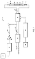
Referring to the drawings, FIG. 1 illustrates a
system 10 in accordance with one embodiment of the
present invention for the operation of a discharge
lamp. The system 10 is provided for operating a high
intensity discharge lamp 12 which, in operation, may
be positioned horizontally, vertically or in any
other orientation. The discharge lamp 12 may be
contained in a sealed outer envelope 14 in a
conventional manner, if desired. The envelope 14 is
illustrated schematically in FIG. 1. The ballast
used to operate lamp 12 is an acoustically modulated
square ballast. Any such ballast with appropriate
modulation may be used provided such ballast is
without the "off-time" or low power time; that is,
with zero crossing time being less than 10
microseconds, and preferably less than one
microsecond. System 10 includes a function generator
and power amplifier combination. In particular, a
function generator, including a sweep ramp 16 and
sine wave generator 18, is provided coupled to a
power amplifier 20. A typical function generator,
including a sweep ramp 16 and a sine wave generator
18, which can be employed is a Model No. BK3020
manufactured by BK Precision. A typical power
amplifier 20 which can be used is a Model No. 1140LA,
manufactured by ENI.
The system 10 includes a dc power supply and resistor
ballast combination. In particular, dc power supply
22 is coupled to a resistor 24 providing a series dc
power supply and resistor ballast combination. A
typical dc power supply 22 which can be used is a
Model No. HP6035A, manufactured by Hewlett Packard.
The resistor 24 is a conventional 25 Ohm non-inductive
power resistor. A typical resistor 24
which can be used is a Model No. Pecos TC100PA10R00J,
manufactured by Ohmite. The output of the ballast
combination is capacitively coupled to the output of
the function generator/power amplifier combination to
provide a dc voltage which is fed to an H-bridge
commutator 26. An example of the H-bridge commutator
26, and dc circuit supply for such commutator, which
can be used is illustrated in FIGS. 2 and 3,
respectively. The capacitive coupling is provided by
a resistor 28 and capacitor 30. The resistor 28 is a
conventional 30 Ohm non-inductive matching power
resistor. A typical resistor 28 which can be used is
a Model No. Pecos TC100PA10R00J, manufactured by
Ohmite. The capacitor 30 is a conventional 1 µF
capacitor. A typical capacitor 30 which can be used
is a Model No. 1µF/K 630V, manufactured by Sprague.
The H-bridge commutator 26 is operatively coupled to
the lamp 12 through a conventional in-rush limiting
resistor 32. A typical resistor 32 which can be used
is a Model No. CL40, manufactured by Panasonic. A
pulse generator 34 is coupled to the H-bridge
commutator 26 for setting the timing of the H-bridge
commutator. To this end, a conventional Hewlett
Packard lap top computer 36 may be coupled to the
pulse generator 34 to provide the desired
instructions in a conventional manner. A typical
pulse generator 34 which can be used is a Model No.
DG535, manufactured by Stanford Research.
The system 10 provides one embodiment of the present
invention useful in controlling a lamp system by (a)
supplying a discharge lamp with an input waveform to
power the discharge lamp, and (b) injecting acoustic
frequencies into the power waveform supplied to the
discharge lamp in the absence of off-time and low
power time.
The discharge lamp 12 includes a conventional sealed
arc tube 38 which defines a discharge space therein.
The arc tube 38 may be transparent or translucent, as
desired. A mercury free halide fill is included
within the discharge space in a conventional manner.
The discharge lamp of the present invention includes
at least one electrode sealed therein for
establishing an arc discharge. For example, the arc
tube 38 comprises two electrodes 42 and 44 sealed
therein at opposite ends in a conventional manner.
Each electrode is adapted to be electrically
connected to a respective connector 46 and 48 thereby
electrically connecting the arc tube 38 to the H-bridge
commutator 26.
In considering the operation of the system
illustrated in FIG. 1, in order to inject acoustic
frequencies into the power waveform supplied to the
arc tube 38, the function generator 16, 18 is tuned
to the desired frequencies. The specific frequencies
will vary depending upon lamp features such as the
dimensions and geometry of the arc tube and the
temperature and composition of the enclosed fill. In
other words, the frequencies will vary from lamp to
lamp as one or more of these features vary.
Regardless of the specifics of the lamp features,
however, a mercury free high intensity discharge lamp
may be positioned in any orientation during operation
thereof, by imposing the particular acoustic
frequency components in the power waveform applied to
the lamp as described herein. To this end, in
considering the embodiment illustrated in FIG. 1, the
function generator 16, 18 is tuned to the desired
acoustic frequencies. A ripply dc voltage as
illustrated in FIG 4 is provided at an input of the
H-
bridge commutator 26 by capacitively coupling the
power amplified swept acoustic waveform provided by
the
tuned function generator 16, 18 and
power
amplifier 20 to the output of the series DC supply
and
resistor ballast combination 22, 24. Such
capacitive coupling is provided by the
resistor 28
and
capacitor 30. In turn, the H-
bridge commutator
26 will produce an acoustically modulated square wave
ballast waveform as illustrated in FIG. 5 which will
be fed to the
arc tube 38 through the
resistor 32
which provides the conventional in-rush limit. An
example of the H-
bridge commutator 26 is illustrated
in FIGS. 2A and 2B (the component values for FIGS. 2A
and 2B are listed in Table I). An example of a dc
circuit supply for such commutator is illustrated in
FIG. 3 (the component values for FIG. 3 are listed in
Table II). Operation of
system 10 using an
appropriately modulated ballast waveform in order to
inject acoustic frequencies provides an arc tube wall
temperature profile which is well within the survival
region for quartz and provides a lamp system which
will have longevity, improved photometric results and
be capable of operating in any orientation without
change in electrical characteristics or light output.
| R1 | 240 ohms |
| R2 | 100 ohms |
| R3 | 1000 ohms |
| R4 |
| | 10 ohms |
| R5 | 110 ohms, 2 watts |
| D1 and D2 | MUR 8100 |
| D3 | 18 volt zener |
| BR1 | RS404L |
| VR1 | Varistor 420L20 |
| C1 | 100 µf 50V |
| C2 | 100 pf |
| C3 | 0.1 µf ceramic |
| Q1 | IRGPH40F (IGBT) |
| U1 | HP3101 |
| | 5 amps |
| F2 | 2 amps |
| C1 | 0.47 µf, 200 VAC |
| C2 | 270 µf, 200 VDC |
| D1 | 1N4006 |
A system was provided including the specific
components described above coupled to a mercury free
metal halide high intensity discharge lamp. The lamp
included a 400 Watt sealed arc tube having a
discharge space containing a mercury free halide fill
which consisted essentially of the composition
DyI
3/HoI
3/TmI
3/NaI/TlI in a molar ratio of
1.0/1.0/1.0/6.0/0.75. The outer diameter of the arc
tube was 10mm (8 mm I.D.) and the tips of electrodes
contained therein were spaced to provide an arc
length of 80mm. The ballast illustrated in FIG. 1
was powered in a conventional manner using the
dc
power supply 22. The lamp provided reasonable
efficacy and color as noted below when operated in a
horizontal orientation:
| Lumens Per Watt (LPW) | 90 |
| Average (R1-R9) Color Rendering Index (CRI RA) | 80 |
| R9 Color Rendering Index (CRI R9) | -20 |
| Correlated Color Temperature at 400 W. (CCT) | 4000 |
However, the lamp could not be operated
satisfactorily when oriented in any other manner such
as when oriented vertically. For example, when
oriented vertically, the arc was destabilized and
pushed towards the glass of the arc tube. The color
was noticeably asymmetrical top to bottom, the top of
the lamp being dim and the bottom of the lamp being
bright. The arc tube wall temperature profile was
within the survival region for quartz but only when
the lamp was oriented horizontally. The arc tube
overheated and failed at the rated power when the
lamp was oriented vertically, the lamp therefore not
universally burning.
EXAMPLE 2
The identical system provided in EXAMPLE 1 was
altered solely by effecting an acoustically modulated
ballast. In particular, the lamp was operated on a
400 Watt acoustically modulated square wave ballast
without the "off-time" or low power time; that is,
less than 10 microsecond, and preferably less than
one microsecond. To this end, the function generator
was tuned to a 1kHz sweep rate and a starting
frequency of about 60 kHz. The range of frequency
was about 50 to 71 kHz. A schematic of the voltage
and current waveforms fed to the lamp by the H-bridge
commutator through the in-rush resistor is
illustrated in FIGS. 6 and 7, respectively. It will
be noted that at 160 volts and 2.3 amps, the
waveforms are symmetric at zero. Under these
conditions, the arc became centered and separated
itself into many segments along the length of the arc
tube. The number of segments varied as the frequency
of the driving signal changed. For example, as the
frequency range increased, the number of segments
increased (multimode). Controlling the number of
cells in multimode operation was found to be
difficult. In single mode (one cell) operation, the
arc appeared straight and centered along the length
of the tube. The lamp provided improved photometric
results including improved efficacy and color as
noted below:
| Lumens Per Watt (LPW) | 95 |
| Average (R1-R9) Coloring Rendering Index (CRI RA) | 82 |
| R9 Coloring Rendering Index (CRI R9) | 0 |
| Correlated Color Temperature at 400 W. (CCT) | 3700 |
In addition to superior efficacy and better color,
the arc was stable and straight, and the asymmetry of
the color was reduced. The lamp achieved these
objectives at any orientation without change in
electrical characteristics or light output. In other
words, the lamp was universally burning when operated
on a modulated ballast waveform as described herein.
The arc tube wall temperature profile was well
within the survival region of quartz in any operating
position of the arc tube. The temperature profile
suggests that the lamp will have longevity. Such
improved results are obtained in combination with the
environmentally attractive feature of providing a
lamp which does not contain mercury.
The embodiments which have been described herein are
but some of several which utilize this invention and
are set forth here by way of illustration but not of
limitation. It is apparent that many other
embodiments which will be readily apparent to those
skilled in the art may be made without departing
materially from the spirit and scope of this
invention.