EP1045384A2 - A multiple disc changing apparatus - Google Patents
A multiple disc changing apparatus Download PDFInfo
- Publication number
- EP1045384A2 EP1045384A2 EP00303080A EP00303080A EP1045384A2 EP 1045384 A2 EP1045384 A2 EP 1045384A2 EP 00303080 A EP00303080 A EP 00303080A EP 00303080 A EP00303080 A EP 00303080A EP 1045384 A2 EP1045384 A2 EP 1045384A2
- Authority
- EP
- European Patent Office
- Prior art keywords
- compact disc
- reading unit
- turntable
- compact
- engagement means
- Prior art date
- Legal status (The legal status is an assumption and is not a legal conclusion. Google has not performed a legal analysis and makes no representation as to the accuracy of the status listed.)
- Withdrawn
Links
Images


Classifications
-
- G—PHYSICS
- G11—INFORMATION STORAGE
- G11B—INFORMATION STORAGE BASED ON RELATIVE MOVEMENT BETWEEN RECORD CARRIER AND TRANSDUCER
- G11B17/00—Guiding record carriers not specifically of filamentary or web form, or of supports therefor
- G11B17/22—Guiding record carriers not specifically of filamentary or web form, or of supports therefor from random access magazine of disc records
- G11B17/226—Guiding record carriers not specifically of filamentary or web form, or of supports therefor from random access magazine of disc records the magazine consisting of a single rotatable tray carrying the disks
Definitions
- This invention relates to a multiple disc changing apparatus and, in particular, although not necessarily solely, a multiple disc turntable for audio, video or computer applications.
- the apparatus will be described with reference to audio compact disc players although the invention can be applied to other apparatus,
- Compact disc players have existed for some years. Initially, the compact disc players utilized a single disc that could be mounted and removed from the unit as desired.
- a common form of multiple compact disc turntable utilizes recesses to position the discs themselves on the turntable.
- the drive and reading unit of the compact disc player engages the disc, lifts the disc from the turntable into position where it may be rotated and plays the disc.
- the difficulty with such conventional apparatus is that the units must be maintained in a relatively stable horizontal position to avoid any dislodgement of the discs when in the out-of-play positions which may cause both damage to the disc as well as causing the disc to be improperly placed if rotated to the in-play position.
- the discs are generally supported laterally in the recess and supported underneath by the turntable itself However there is no retention of the disc within the recess other than that provided by gravity.
- compact disc players which can be arranged in the vertical position.
- a typical example of such an apparatus securely fixes the disc onto the drive spindle so that, even in the vertical position, the disc is securely held.
- the securing of the discs in this position has involved such apparatus as retaining means on the spindle itself in the form of spring biased ball bearings protruding from the spindle.
- the compact disc is fitted over the spindle and pushed past the ball bearings which must recess into the spindle to allow the compact disc to be fitted in place.
- the spring bias then causes the ball bearings to protrude on the far side of the compact disc from the seat provided on the drive spindle.
- the invention may broadly be said to consist in a multiple compact disc player including:
- the invention may broadly be said to consist in a rotatable support means for a compact disc player having a reading unit to retrieve information from a compact disc including:
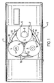
- This invention relates to a multiple compact disc player 1, a preferred embodiment of which is shown in Fig. 1.
- the preferred embodiment described is for an audio compact disc player.
- the invention may be applied whenever suitable.
- the multiple compact disc player 1 as shown in Fig. 1 has a rotatable support means 2 in the form of a turntable rotatable about a central axis 3.
- a plurality of compact discs 4 may be placed on the rotatable support means 2 in selected positions.
- the selected positions will be defined by means of recesses 5 into the generally planar turntable 2 so that the discs 4 are supported in the plane of the turntable 2 by the edges of the recess 5.
- Alternative means can be used to define the selected positions provided these means are capable of retaining the discs 4 in a position relative to the rotatable support means 2.
- a series of projections from the turntable 2 around the outer edge of the compact disc 4 could be utilized.
- the discs 4 will not be supported by their central aperture 6 while on the turntable 2 as this aperture is generally left clear for engagement of a drive and reading unit 7.
- a driving and reading unit 7 is provided to engage the compact disc 4 once positioned adjacent the unit 7.
- the driving and reading unit 7 works in co-operation with the top support 8.
- the unit 7 contains a drive spindle which engages an adjacent compact disc 4, lifts the disc from the turntable or rotatable support means 2 and rotates the disc 4 to be read by the information retrieval means contained on the unit 7.
- the top support 8 may comprise a magnetic top plate which is loosely supported in a upper arm 9. The top magnetic support is magnetically attracted to the seat for the compact disc provided on the drive spindle of the reading unit 7. This sandwiches the compact disc 4 between the paramagnetic and the seat on the spindle to avoid eccentric rotation and slippage of the compact disc on the seat of the drive spindle.
- compact disc 4 may be accommodated in selected positions on the turntable 2.
- compact disc 4 can be released by the reading unit 7 to reside on the rotatable support means 2, the rotatable support means 2 rotated to bring a further compact disc 4 adjacent reading unit 7 and the reading unit 7 engage the further compact disc as desired.
- the particular number of selected positions or compact discs provided on the turntable does not affect the invention although there would be no need for the rotatable feature unless at least two compact discs can be accommodated.
- releasable engagement means 10 are provided around the perimeter of each of the selected positions on the rotatable support means 2.
- the engagement means 10 engaged partially over an outer edge 11 of the compact discs 4 so that the compact disc 4 is not only supported in plane with the turntable 2 by the recess 5 but also engaged or retained on the turntable 2 by the engagement means 10.
- This engagement means allows the multiple compact disc player 1 or at least the rotatable support means 2 to be oriented in positions other than the horizontal including a vertical position without the discs 4 becoming dislodged from the rotatable turntable 2.
- the engagement means 10 can be provided in a variety of manners although this preferred embodiment provides the engagement means as at least a pair of opposed engagement means overlapping the outer edge 11 of the disc 4. Alternative configurations or forms of the engagement means 10 may be provided.
- the pair of engagement means 10 adjacent the compact disc 4 currently engaged with the reading unit 7 are withdrawn and spaced apart from the outer edge 11 of the disc 4.
- the reading unit lifts the compact disc from the turntable 2 so that it may be freely rotated according to the requirements of the reading unit 7 and under the control of a drive spindle associated with the reading unit 7 and not contact the turntable 2 so as to interfere with that operation.
- the engagement means 10 is provided in a releasable manner to release the compact disc 11 once engaged by the drive spindle and reading unit 7.
- Figs. 2 through 5 show the turntable 2, reading unit 7 and associated apparatus in considerably more detail. This particular preferred embodiment shown in these figures is the same as that previously described for Fig. 1.
- Figs. 2 and 3 show the preferred embodiment in a first configuration. This first configuration is the same as that shown in Fig. 1 in which a compact disc adjacent to reading unit is currently engaged with the reading unit. Figs. 3 and 4 are directed to the same preferred embodiment in a second configuration as the adjacent compact disc is released by the reading unit and re-engaged by its associated engagement means.
- the rotatable support means 2 can be seen to support three compact discs, 4a, 4b and 4c.
- Each of the compact discs, 4a, 4b and 4c is supported in a selected position 5a, 5b and 5c in the form of a recess of slightly larger diameter than the diameter of the compact discs.
- each selected position and compact disc has a pair of engagement means 10a, 10b and 10c. Furthermore, each of those engagement means are biased into the engaged position with the associated compact discs by biasing means 12a, 12b and 12c.
- the biasing means of this preferred embodiment are steel springs and as the engaged position for the engagement means 10a, 10b and 10c is required in a plurality of positions to which the turntable may be rotated and the unengaged position currently defined by engagement means 10a is only required when the disc is adjacent the reading unit 7, it is preferred that the bias on the engagement means is orientated to bias this into engagement and the bias is only overcome in the position adjacent the reading unit.
- the alternative construction of biasing these engagement means to the unengaged position when adjacent the reading unit and manoeuvring the items against that bias in all other positions is a possible, although less desirable, option.
- each of the pair of engagement means is provided with a slot 14 which has an angled face 15 defining a broader opening to the slot 14 towards the perimeter of the turntable 2 than the interior end of the engagement means 10c.
- This angled face 15 may act as a cam when engaging a sliding projection 16 provided on either side of the reading unit 7.
- the numerals 14 and 15 have been omitted from the other engagement means 10a and 10b for clarity although identical slots and angled faces are provided on those as well.
- the projection 16 can slide and engage within the slot 14 to retain the engagement means 10a in a position in which the engagement means is spaced from the outer perimeter 11a of the compact disc 4a.
- the angled or cam face 15 assists as the projection 16 slides into the slot 14 from the outer perimeter of the turntable 2.
- the sliding projection 16 will engage the outer edge of the cam face 15 and while moving in a linear direction, cause transverse motion of the corresponding engaging means to withdraw the engaging means from engagement with the compact disc.
- the sliding projection can be provided to work from the general direction of the interior of the turntable towards the exterior by reversing the direction of the slot 14 and cam face 15 on the engagement means 10. It is merely considered preferable to arrange the components in the manner as shown in this embodiment
- the sliding projection 16 is attached to an arm 17 or other suitable drive means which itself is connected to a sliding plate 18.
- the sliding plate 18 has side plates 19 and 20 which extend either side of the reading unit 7. Support for the reading unit 7 is provided by engagement of pins 21 and 22 as shown in Fig. 3 into side plate 19 and similar projections into side plate 20 on the other side of the reading unit 7.
- the pins or other suitable engagement means 21 and 22 are contained within angle slots 23 and 24 on side plate 19. Further, the reading unit 7 is retained by a housing or similar (not shown) so that the only free movement available to the reading unit 7 is substantially transverse to the plane of the compact disc 4a or the general plane of the turntable 2. In Fig. 3, the reading unit 7 moves in a vertical position to the limit of travel indicated by dash line 25 on Fig. 3.
- the reading unit 7 is provided with a drive spindle 26 which is engaged through the compact disc 4a such that an extending flange 27 acts as a seat for the compact disc 4a.
- the substantially transverse movement of the reading unit 7 with respect to the general plane of the turntable 2 between the first and second configurations causes the drive spindle 26 to engage through the central aperture of the compact disc 4a.
- the seat 27 lifts the compact disc from its recess in the turntable 2 so that it may be rotated freely under control from the drive spindle 26.
- the magnetic top support 8 is also shown in Fig. 3 and is magnetically attracted to the seat 27 to sandwich the compact disc 4a therebetween.
- this preferred embodiment utilizes a linear motion of the reading unit 7
- other conventional apparatus for substantially horizontal applications utilizes a rotational motion of the reading unit 7 to engage the compact disc.
- a rotational motion of the reading unit 7 to engage the compact disc.
- hinges one edge of the reading unit 7 such as the edge 28 in Fig. 3.
- the hinged edge 28 will remain fixed but rotatably attached to a suitable mounting and the distal free edge of the reading unit 7 is raised and lowered to rotate about a hinge on edge 28.
- Such rotational movement is considered less desirable for the present application.
- the reading unit 7 is provided with drive means in the form of a motor 29 or similar apparatus to cause rotation of the drive spindle 26 as well as an optical reading unit to read the disc.
- the arm 17 has also moved laterally with the sliding member 18 due to the connection 31 therebetween.
- a pin or other guide means 32 supported from an adjacent stationary portion such as the housing of the compact disc player can be engaged within a co-operating slot 33 such that the sliding projection is not only moved out of the adjacent slot 14 in the engagement means 10a but also lowered through the provision of the angled faces in the slot 33. This lowering of the projection 16 assists in removing the projection 16 from interfering with rotation of the turntable 2.
- the initial movement of the arm 17 from the position in Fig. 3 to the position shown in Fig. 5 is a generally lateral motion courtesy of the initial portion of slot 33 being substantially parallel to the sliding member 18. This ensures that the projection 16 engages and disengages along the length of the slot 14 and cam face 15 to ease a gradual movement of the engagement means 10a.
- the latter part of slot 33 contains the angled faces to draw the projection 16 away from the plane of the turntable 2,
- connection 31 between the arm and the sliding member 18 is a pivotal connection to support this movement of the arm 17.
- the sliding member 18 can be driven through its movement by a suitable drive mechanism of its own or, driven from the same drive means that causes rotation of the turntable 2.
- the drive mechanism needs to accommodate no rotation of the turntable 2 while the sliding member 18 is moved after which rotation of the turntable can then occur
- the invention provides a multiple disc compact disc player or at least a turntable and associated engagement means which allow the substantially vertical orientation of the turntable 2.
- the compact discs are retained in place in the out-of-play position by engagement means 10 and, once engaged by the drive spindle 26, a timed release of the engagement means 10 occurs to release only that compact disc so engaged by the drive spindle 26.
- the disc may then be positioned relative to the reading unit 7 for retrieval of the information contained on the disc.
- the reading unit 7 moves in a substantially linear fashion rather than rotationally about a hinged edge to provide more accurate and better placement of the drive spindle 26 on the compact disc. This is particularly advantageous when co-operating with the engagement means 10 to cause timed release of the compact disc.
Landscapes
- Holding Or Fastening Of Disk On Rotational Shaft (AREA)
- Feeding And Guiding Record Carriers (AREA)
Abstract
Description
- a rotatable support means for the support of at least two compact discs in selected positions;
- a reading unit to engage and retrieve information from a compact disc;
- a drive means to rotate said rotatable support means such that a selected compact disc may be placed in a position to engage said reading unit; and
- an engagement means on or in association with said rotatable support means to retain said compact discs not engaged by said reading unit in said selected positions on said rotatable support means.
- a rotatable support means having at least two positions for placement
of compact discs; and
- releasable engagement means to retain said compact discs in said selected positions and selectively release a compact disc when said compact disc is engaged by said reading unit of said compact disc player.
- Fig. 1 shows an elevation view of a preferred embodiment of the apparatus;
- Fig. 2 shows a plan view of a portion of the apparatus of Fig. 1 in a first configuration;
- Fig. 3 shows an elevation view of the portion of Fig. 2 in said first configuration;
- Fig. 4 shows a plan view of the portion of the apparatus of Fig. 2 in a second configuration; and
- Fig. 5 shows an elevation view of the portion of the apparatus of Fig. 4 in said second configuration.
Claims (6)
- A multiple compact disc player includinga rotatable support means for the support of at least two compact discs in selected positions;a reading unit to engage and retrieve information from a compact disc;a drive means to rotate said rotatable support means such that a selected compact disc may be placed in a position to engage said reading unit; andan engagement means on or in association with said rotatable support means to retain said compact discs not engaged by said reading unit in said selected positions on said rotatable support means.
- A multiple compact disc player as claimed in claim 1 wherein said engagement means comprise at least one engagement member positioned around a periphery of said selected positions and movable between an engaged and a disengaged position.
- A multiple compact disc player as claimed in claim 2 wherein said engagement means are moved between said engaged and disengaged positions by a drive means interconnected with said reading unit such that movement of said reading unit to an engaged position with said compact disc creates a disengagement of said engagement means.
- A multiple compact disc player as claimed in claim 1 wherein said reading unit engages said compact disc through substantially transverse motion of said reading unit with respect to a plane of said rotatable support means.
- A multiple compact disc player as claimed in claim 1 wherein said rotatable support means comprises a turntable to support a plurality of compact discs in selected positions.
- A rotatable support means for a compact disc player having a reading unit to retrieve information from a compact disc including:a rotatable support means having at least two positions for placement of compact discs; andreleasable engagement means to retain said compact discs in said selected positions and selectively release a compact disc when said compact disc is engaged by said reading unit of said compact disc player.
Applications Claiming Priority (2)
| Application Number | Priority Date | Filing Date | Title |
|---|---|---|---|
| US289749 | 1999-04-12 | ||
| US09/289,749 US6285633B1 (en) | 1999-04-12 | 1999-04-12 | Multiple disc changing apparatus |
Publications (2)
| Publication Number | Publication Date |
|---|---|
| EP1045384A2 true EP1045384A2 (en) | 2000-10-18 |
| EP1045384A3 EP1045384A3 (en) | 2001-04-11 |
Family
ID=23112911
Family Applications (1)
| Application Number | Title | Priority Date | Filing Date |
|---|---|---|---|
| EP00303080A Withdrawn EP1045384A3 (en) | 1999-04-12 | 2000-04-12 | A multiple disc changing apparatus |
Country Status (3)
| Country | Link |
|---|---|
| US (1) | US6285633B1 (en) |
| EP (1) | EP1045384A3 (en) |
| CN (1) | CN2424515Y (en) |
Family Cites Families (7)
| Publication number | Priority date | Publication date | Assignee | Title |
|---|---|---|---|---|
| US5123005A (en) | 1989-12-28 | 1992-06-16 | Sony Corporation | Disc tray loading mechanism for reducing loading and unloading mechanical shocks |
| DE4121297C2 (en) | 1990-06-27 | 1995-05-11 | Haitai Electronics Co | Device for automatically storing and reissuing optical data storage disks |
| JP3064720B2 (en) | 1992-04-22 | 2000-07-12 | 松下電器産業株式会社 | Disc loading device |
| JP2988169B2 (en) * | 1993-01-12 | 1999-12-06 | 松下電器産業株式会社 | Disc changer |
| TW412722B (en) * | 1995-06-05 | 2000-11-21 | Cd Server Corp | Disc changer with safe and efficient disc handling |
| KR19980061646A (en) * | 1996-12-31 | 1998-10-07 | 배순훈 | Tray roulette rotation control device of optical disk framer system |
| GB2325078B (en) * | 1997-05-06 | 1999-03-24 | Alco Electronics Ltd | Multiple medium-storage disc changer |
-
1999
- 1999-04-12 US US09/289,749 patent/US6285633B1/en not_active Expired - Lifetime
-
2000
- 2000-04-12 CN CN00209216U patent/CN2424515Y/en not_active Expired - Lifetime
- 2000-04-12 EP EP00303080A patent/EP1045384A3/en not_active Withdrawn
Also Published As
| Publication number | Publication date |
|---|---|
| CN2424515Y (en) | 2001-03-21 |
| EP1045384A3 (en) | 2001-04-11 |
| US6285633B1 (en) | 2001-09-04 |
Similar Documents
| Publication | Publication Date | Title |
|---|---|---|
| US5737293A (en) | Disc loading apparatus for loading optical discs in a cartridge or without | |
| CA2024839C (en) | Automatic disc changer apparatus | |
| JPH0675329B2 (en) | Disc player | |
| JPWO1998040886A1 (en) | disk device | |
| JPWO1998040887A1 (en) | Disk device | |
| US5323379A (en) | Disk clamping apparatus including a clamp having a plurality of clamp jaws movable horizontally | |
| JPWO1998040888A1 (en) | Disk device | |
| US5054016A (en) | Automatic disc centering mechanism | |
| US6388974B1 (en) | Recording medium driving apparatus | |
| US5341352A (en) | Disk player for playing back more than one kind of disk | |
| US6285633B1 (en) | Multiple disc changing apparatus | |
| HK1032285A (en) | A multiple disc changing apparatus | |
| US6058097A (en) | Changer-type disk playback device | |
| JPH11162068A (en) | Disk unit | |
| JPH06259864A (en) | Disc player | |
| EP1634285A1 (en) | Appliance with a data carrier disk drive and method of inserting a data carrier in such an appliance | |
| US20030048732A1 (en) | Disk drive | |
| JPH06259869A (en) | Disc player | |
| JP3533829B2 (en) | Optical disk drive | |
| JPH0828025B2 (en) | Disc changer | |
| US7096476B2 (en) | Disk table rotation supporting structure | |
| JPH0438665A (en) | Tray lock device for disk player | |
| JPH07334911A (en) | Disc player | |
| KR900002509Y1 (en) | Spindle Drive of Optical Disc Player | |
| JP2001222845A (en) | Disk insertion / ejection mechanism of disk unit |
Legal Events
| Date | Code | Title | Description |
|---|---|---|---|
| PUAI | Public reference made under article 153(3) epc to a published international application that has entered the european phase |
Free format text: ORIGINAL CODE: 0009012 |
|
| AK | Designated contracting states |
Kind code of ref document: A2 Designated state(s): AT BE CH CY DE DK ES FI FR GB GR IE IT LI LU MC NL PT SE |
|
| AX | Request for extension of the european patent |
Free format text: AL;LT;LV;MK;RO;SI |
|
| PUAL | Search report despatched |
Free format text: ORIGINAL CODE: 0009013 |
|
| RIC1 | Information provided on ipc code assigned before grant |
Free format text: 7G 11B 17/18 A, 7G 11B 17/12 B, 7G 11B 17/10 B, 7G 11B 17/04 B, 7G 11B 17/028 B, 7G 11B 17/022 B, 7G 11B 17/02 B, 7G 11B 17/00 B, 7G 11B 17/26 B |
|
| AK | Designated contracting states |
Kind code of ref document: A3 Designated state(s): AT BE CH CY DE DK ES FI FR GB GR IE IT LI LU MC NL PT SE |
|
| AX | Request for extension of the european patent |
Free format text: AL;LT;LV;MK;RO;SI |
|
| 17P | Request for examination filed |
Effective date: 20010607 |
|
| AKX | Designation fees paid |
Free format text: AT BE CH CY DE DK ES FI FR GB GR IE IT LI LU MC NL PT SE |
|
| STAA | Information on the status of an ep patent application or granted ep patent |
Free format text: STATUS: THE APPLICATION IS DEEMED TO BE WITHDRAWN |
|
| 18D | Application deemed to be withdrawn |
Effective date: 20060502 |
|
| REG | Reference to a national code |
Ref country code: HK Ref legal event code: WD Ref document number: 1032285 Country of ref document: HK |