EP1045309A1 - Wavelet transform method and apparatus - Google Patents
Wavelet transform method and apparatus Download PDFInfo
- Publication number
- EP1045309A1 EP1045309A1 EP00400900A EP00400900A EP1045309A1 EP 1045309 A1 EP1045309 A1 EP 1045309A1 EP 00400900 A EP00400900 A EP 00400900A EP 00400900 A EP00400900 A EP 00400900A EP 1045309 A1 EP1045309 A1 EP 1045309A1
- Authority
- EP
- European Patent Office
- Prior art keywords
- blocks
- samples
- transformation
- signal
- coding
- Prior art date
- Legal status (The legal status is an assumption and is not a legal conclusion. Google has not performed a legal analysis and makes no representation as to the accuracy of the status listed.)
- Withdrawn
Links
Images





Classifications
-
- H—ELECTRICITY
- H04—ELECTRIC COMMUNICATION TECHNIQUE
- H04N—PICTORIAL COMMUNICATION, e.g. TELEVISION
- H04N19/00—Methods or arrangements for coding, decoding, compressing or decompressing digital video signals
- H04N19/60—Methods or arrangements for coding, decoding, compressing or decompressing digital video signals using transform coding
- H04N19/63—Methods or arrangements for coding, decoding, compressing or decompressing digital video signals using transform coding using sub-band based transform, e.g. wavelets
- H04N19/64—Methods or arrangements for coding, decoding, compressing or decompressing digital video signals using transform coding using sub-band based transform, e.g. wavelets characterised by ordering of coefficients or of bits for transmission
- H04N19/645—Methods or arrangements for coding, decoding, compressing or decompressing digital video signals using transform coding using sub-band based transform, e.g. wavelets characterised by ordering of coefficients or of bits for transmission by grouping of coefficients into blocks after the transform
-
- G—PHYSICS
- G06—COMPUTING OR CALCULATING; COUNTING
- G06F—ELECTRIC DIGITAL DATA PROCESSING
- G06F17/00—Digital computing or data processing equipment or methods, specially adapted for specific functions
- G06F17/10—Complex mathematical operations
- G06F17/14—Fourier, Walsh or analogous domain transformations, e.g. Laplace, Hilbert, Karhunen-Loeve, transforms
- G06F17/148—Wavelet transforms
Definitions
- the present invention concerns the transformation of a digital signal, such as digital filtering.
- Digital signal analysis filterings are envisaged here by way of example.
- wavelet transformations are more particularly envisaged.
- filterings are generally subassemblies integrated into the coding and/or decoding assemblies. They often require a large amount of random access memory or buffer space for storing the data in the course of processing.
- the most conventional solutions for producing the wavelet transform consist of loading the entire image to be processed into memory and then effecting the different filtering steps. The memory space is then so large that this makes it difficult to implement such filterings in appliances such as photographic appliances, facsimile machines, printers or photocopiers for example.
- the present invention provides a method and a device for transforming a digital signal which minimises the degree to which the data being processed occupy buffer space.
- the invention proposes a method of transforming a digital signal representing a physical quantity, into signals of frequency sub-bands distributed in at least two different frequency bands and in at least two different resolutions, characterised in that it includes steps of:
- the transformation is a wavelet transformation.
- the first blocks overlap in pairs on a predetermined fourth number of samples or the first blocks are adjacent.
- the overlap between adjacent blocks improves the quality of the reconstructed signal after processing.
- the first blocks are processed in a predetermined order, such that the signal is transformed zone by zone, a zone of the signal being processed at all resolution levels before passing to a following zone.
- the memory requirements are minimised.
- the grouping of the second blocks is effected by grouping together second blocks having the same number of samples and samples selected according to the same frequency band. This is because blocks are grouped together having samples of the same nature, so that their subsequent processing is optimised.
- the digital signal is an image signal.
- the invention applies advantageously to an image signal, which generally requires a large amount of memory space. This memory space is reduced by virtue of the invention.
- the invention also concerns a coding method which includes the characteristics set out above and has the same advantages.
- the invention proposes a device for transforming a digital signal representing a physical quantity, into signals of frequency sub-bands distributed according to at least two different frequency bands and according to at least two different resolutions, characterised in that it has;
- the device has means of implementing the characteristics set out above.
- the invention also concerns a coding device, a digital appliance including the transformation or coding device or means of implementing the transformation or coding method.
- This digital appliance is for example a digital photographic appliance, a computer, a facsimile machine, a photocopier, a scanner or a printer.
- An information storage means which can be read by a computer or by a microprocessor, integrated or not into the device, possibly removable, stores a program implementing the filtering method.
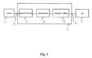
- a data processing device is a data coding device 2 which has an input 2 1 to which a source 1 of uncoded data is connected.
- the source 1 has for example a memory means, such as a random access memory, a hard disk, a diskette or a compact disc, for storing uncoded data, this memory means being associated with a suitable reading means for reading the data therein.
- a means for recording the data in the memory means can also be provided.
- the data to be coded are a series of digital samples representing an image IM.
- the source 1 supplies a digital image signal SI at the input of the coding circuit 2.
- the image signal SI is a series of digital words, for example bytes. Each byte value represents a pixel of the image IM, here with 256 grey levels, or black and white image.
- the image can be a multispectral image, for example a colour image having components in three frequency bands, of the red-green-blue or luminance and chrominance type. Each band is then processed in a similar fashion to the monospectral image.
- Means 3 using coded data are connected at the output 2 2 of the coding device 2.
- the user means 3 include for example coded data storage means, and/or coded data transmission means.
- the coding device 2 includes conventionally, as from the input 2 1 , a transformation circuit 2 3 , to which the present invention more particularly relates, and an example embodiment of which will be detailed hereinafter.
- the transformations envisaged here are decompositions into frequency sub-bands signals of the data signal, so as to effect an analysis of the signal.
- the analysis is performed on at least two resolution levels, the resolution of a signal being in general terms the number of samples per unit length which are used for representing the signal.
- the transformation circuit 2 3 is connected to a quantisation circuit 2 4 .
- the quantisation circuit implements a quantisation known per se, for example a scalar quantisation, or a vector quantisation, of the coefficients, or groups of coefficients, of the frequency sub-band signals supplied by the circuit 2 3 .
- the circuit 2 4 is connected to an entropic coding circuit 2 5 , which effects an entropic coding, for example a Huffman coding, or an arithmetic coding, of the data quantised by the circuit 2 4 .
- an entropic coding for example a Huffman coding, or an arithmetic coding
- the coding device can be integrated into a digital appliance, such as a computer, a printer, a facsimile machine, a scanner or a digital photographic apparatus, for example.
- a digital appliance such as a computer, a printer, a facsimile machine, a scanner or a digital photographic apparatus, for example.
- the device 10 is here a microcomputer having a communication bus 101 to which there are notably connected:
- the device 10 can include, in a conventional fashion, a keyboard or a disk drive adapted to receive a diskette, or can be adapted to communicate with a communication network.
- the device 10 can receive data to be coded from a peripheral device, such as a digital photographic apparatus, or a scanner, or any other means of acquiring or storing data.
- a peripheral device such as a digital photographic apparatus, or a scanner, or any other means of acquiring or storing data.
- the device 10 can also receive data to be coded from a distant device, via the communication network, and transmit coded data to a distant device, again via the communication network.
- the random access memory 103 is a direct-access dynamic memory, known as DRAM, from the English “Dynamic Random Access Memory”. This memory is useful in the context of the invention for reading the samples of the image in a particular order, as disclosed below.
- the circuit 104 also has a Static Random Access Memory known as SRAM.
- the programs according to the present invention are stored in a storage means.
- This storage means can be read by a computer or by a microprocessor.
- This storage means is integrated or not into the device, and may be removable. For example, it may have a magnetic tape, a diskette or a CD-ROM (fixed-memory compact disc).
- FIG. 3 With reference to Figure 3 , there is described an example of a device 300 implementing the invention. This device is adapted to code and/or decode a digital signal.
- the device 300 is here a microcomputer having a communication bus 301 to which there are connected:
- the hard disk 308 stores the programs implementing the invention, which will be described hereinafter, as well as the data to be coded and the data coded according to the invention. These programs can also be read on the diskette 310, or received via the communication network 313, or stored in the read only memory 302.
- the programs according to the present invention are stored in a storage means.
- This storage means can be read by a computer or by a microprocessor.
- This storage means is integrated or not into the device, and may be removable. For example, it may have a magnetic tape, a diskette or a CD-ROM (fixed-memory compact disc).
- the random access memory includes a buffer.
- the device 300 can receive data to be coded from a peripheral device 307, such as a digital photographic apparatus, or a scanner, or any other means of acquiring or storing data.
- a peripheral device 307 such as a digital photographic apparatus, or a scanner, or any other means of acquiring or storing data.
- the device 300 can also receive data to be coded from a distant device, via the communication network 313, and transmit coded data to a distant device, again via the communication network 313.
- the device 300 can also receive data to be coded from the microphone 311. These data are then a sound signal.
- the screen 304 enables a user notably to display the data to be coded, and serves, with the keyboard 314, as a user interface.
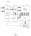
- Figure 4 depicts an embodiment of the coding circuit 104 according to the invention.
- the circuit 104 includes:
- the module 21 has data inputs and address outputs connected to the random access memory 103.
- the module 21 also has outputs connected to the vertical filtering module 22.
- the module 21 makes it possible to sequence the samples to be processed in a specific order and to store them before they are processed.
- the vertical filtering module 22 effects a filtering in the vertical direction of the image and has outputs connected to the horizontal filtering module 23.
- the horizontal filtering module 23 effects a filtering in the horizontal direction of the image and has outputs connected to the modules 24 and 25.
- the horizontal filtering module can be placed before the vertical filtering module.
- the module 24 has an output connected to the vertical filtering module 22.
- the module 25 has outputs connected to the quantisation and entropic coding module 26.
- quantisation and entropic coding are conventional and will not be detailed here.
- the modules 21, 22, 23, 24 and 25 are detailed hereinafter.
- the operation of the circuit 104 is approximately as follows.
- the filtering is effected by blocks of samples.
- a block is a group of samples selected in the image.
- the blocks are here rectangular in shape, with an overlap between adjacent blocks which is zero or one row and/or one column of samples. All the blocks have the same number of samples, so that they are all filtered in an identical fashion.
- the samples of the image to be coded are read in the memory 103 in a fashion sequenced by the module 21, in the form of blocks which are then filtered in the two vertical and horizontal directions by the modules 22 and 23. Each block is thus analysed according to its frequencies so as to be transformed into four sub-blocks by the modules 22 and 23.
- the analysis is then carried out on at least two resolution levels, that is to say the sub-blocks containing samples of low frequency in the two analysis directions, obtained at at least one first resolution level, are filtered in their turn by the modules 22 and 23. This looping is effected at least once. Each block of the initial image is analysed according to all the required resolution levels.
- the sub-blocks which do not contain samples of low frequency in the two analysis directions obtained at the first resolution level are supplied to the module 25 and are then quantised and coded entropically by the module 26.
- the latter is adapted to process blocks of fixed predetermined size, chosen so as to be equal to that of the sub-blocks obtained at the first resolution level.
- the blocks obtained at the lower resolution levels have sizes smaller than that required by the module 26. These blocks are consequently grouped so as to form blocks having the required size.
- the sub-blocks containing samples of low frequency in the two analysis directions are supplied to the module 24, in order to effect the looping mentioned above, except for the last resolution level of the decomposition, where the sub-blocks are supplied to the module 25.
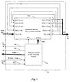
- Figure 5 depicts the buffer memory module 21 for reorganising data in it.
- the circuit 21 makes it possible to read the data in an order predetermined in the original image.
- Figure 6 depicts part of the image to be coded.
- the filtering of the image is effected by blocks. Consequently the image is divided into blocks of samples B i , where i is an integer which represents the rank of the block.
- i is an integer which represents the rank of the block.
- square blocks of size 64x64 samples are considered hereinafter.
- these blocks can overlap between adjacent blocks over a predetermined number of rows and/or over a predetermined number of columns.
- Each block then includes (64(+1))x(64(+1)) samples.
- the samples are read in a predetermined order, for example in a zigzag scanning from the top left-hand corner to the bottom righthand corner.
- the blocks are themselves processed in an ordered fashion, in an order which minimises the memory occupation of the data currently being processed.
- the blocks are considered and processed by groups of four adjacent blocks, such as the blocks B 1 , B 2 , B 3 and B 4 .
- the groups of four blocks are themselves considered in subgroups of four blocks, referred to as macroblocks.
- the order of processing of the blocks for a decomposition of three resolution levels is depicted in Figure 6 by a continuous line.
- the four blocks in a group are run through before passing to the following group.
- a macroblock is totally run through before passing to the following macroblock. It should be noted that, within a group of four blocks, the blocks are processed in any order. Likewise, within a macroblock, the groups are processed in any order.
- This order of processing makes it possible to filter the image by zones, at all resolution levels. Thus only the data of the current zone are kept in memory, and are filtered at all the required resolution levels.
- the number of blocks included in a macroblock depends on the number of resolution levels. Thus one macroblock has 16 blocks for three resolution levels, 64 blocks for four resolution levels and 256 blocks for five resolution levels.
- the module 21 has a random access memory 210 and a reordered address generator 211.
- the address generator 211 is controlled by the signals Hsync, Vsync and ACT supplied by the controller 20.
- the address generator 211 supplies an address signal ADR in seven bits to the random access memory 210 and controls the writing of the data in this memory by the signal WE.
- the address generator 211 supplies an address signal ADR1 to the random access memory 103 and control signals D1 and D2.
- the data are read in the memory 103 in series of 64(+1) bytes.
- the data are written in the memory 210 in accordance with a reading-modification-writing scheme.
- the memory 210 has five inputs DI1 to DI5 and five outputs DO1 to DO5.
- the input DI1 receives eight bits from the memory 103.
- the outputs DO1 to DO4 are respectively connected to the inputs DI2 to DI5.
- the memory 210 is thus a shift register having a depth of five bytes and a width of 64(+1) bytes.
- the memory 210 supplies five bytes at a time to the vertical filtering module 22.
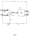
- the vertical filtering module has a multiplexer 220 and a vertical filtering circuit 221.
- a first input of the multiplexer 220 is connected to the module 21 whilst the second input of the multiplexer 220 is connected to the module 24, which will be described below.
- An output of the multiplexer 220 is connected to an input of the filtering circuit 221.
- the controller 20 supplies a control signal NIV in order to indicate which is the resolution level of the data to be filtered.
- NIV the control signal
- the multiplexer selects the data coming from the module 21.
- the five bytes are thus formed into five words each of sixteen bits, setting the unused bits to zero.
- the format of the data to be filtered is compatible with the functioning of the circuit 221.
- the selected data are those coming from the module 24. These data are received in the form of five words each of sixteen bits.
- the circuit 221 receives as an input five words each of sixteen bits and effects a wavelet filtering in so-called "lifting" form, as described for example in French patent application No 98 08824.
- the filter used here is a 5/3 filter. Other methods of effecting wavelet filtering are possible, for example by convolution.
- the circuit 221 supplies to the module 23 two flows each of sixteen bits, one of which includes low-frequency samples and the other high-frequency samples.
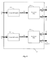
- Figure 8 depicts the horizontal filtering module 23 which has two shift registers 220 and 231 and two filtering circuits 232 and 233.
- the shift register 230 receives the high-frequency samples from the module 22, forms five words each of 16 bits and applies them to the filtering circuit 232.
- the latter similar to the filtering circuit 221, works here on 80 input bits and effects a wavelet filtering in the horizontal direction and supplies as an output two flows each of 16 bits.
- One of these flows has samples of high frequency in the two analysis directions and the other samples of high frequency in the vertical direction and samples of low frequency in the horizontal direction.
- the shift register 231 receives the low-frequency samples from the module 22, forms five words each of 16 bits and applies them to the filtering circuit 233.
- the latter similar to the filtering circuit 232, works here on 80 input bits and effects a wavelet filtering in the horizontal direction and supplies as an output two flows each of 16 bits.
- One of these flows includes samples of low frequency in the two analysis directions and the other samples of low frequency in the vertical direction and samples of high frequency in the horizontal direction.
- the module 23 thus has four outputs connected to four inputs of the memory module 25.
- the outputs supplying the flow of samples of low frequency in the two analysis directions is also connected to the memory module 24.
- the filtering of a block B i thus results, at the first decomposition level, in four blocks LL i,1 , LH i,1 , HL i,1 and HH i,1 .
- the block LL i,1 has a size of (32(+1))x(32(+1)) samples, whilst the blocks LH i,1 , HL i,1 and HH i,1 each have a size of 32x32 samples.
- the block LL i,1 contains samples of low frequency in the two analysis directions
- the block LH i,1 contains samples of high frequency in a first analysis direction and of low frequency in the other analysis direction
- the block HL i,1 contains samples of low frequency in the first analysis direction and of high frequency in the other analysis direction
- the block HH i,1 contains samples of high frequency in the two analysis directions.
- the block LL i,1 When the block LL i,1 is in its turn filtered, this gives four blocks LL i,2 , LH i,2 , HL i,2 and HH i,2 at the second resolution level.
- the block LL i,2 has a size of (16(+1))x(16(+1)) samples and the blocks LH i,2 , HL i,2 and HH i,2 each have a size of 16 x 16 samples.
- the block LL i,2 can in its turn be filtered, and so on.
- the blocks which contain samples of low frequency in one analysis direction have, at each decomposition level, an overlap in this analysis direction which is divided by two compared with the previous level, and then rounded up.
- the blocks which contain samples of high frequency in one analysis direction have, at each decomposition level, an overlap in this analysis direction which is divided by two compared with the previous level, and then rounded down.
- the overlap of the blocks which contain samples of high frequency in at least one analysis direction is eliminated.
- the overlap of the blocks which contain samples of low frequency in the two analysis directions is eliminated only at the end of the last decomposition level.
- Figure 9 depicts the buffer memory module 24, which has a buffer memory 240, an address generator 241 and a circular shift register 242.
- the address generator 241 receives control signals from the controller 20.
- the signal PBV indicates that the data on the input bus are valid.
- the signal PS indicates which resolution level is currently being processed.
- the address generator 241 supplies a write control signal WE to the memory 240, and an address signal AD1.
- the addresses are here expressed in nine bits.
- the memory 240 receives the low-frequency sub-bands resulting from the decomposition of the blocks by the filtering modules 22 and 23, except for the lowest resolution level, since the data of this last decomposition level are not analysed.
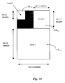
- Figure 10 illustrates the organisation of the memory 240.
- the memory 240 contains three areas for storing the low-frequency sub-bands LL i,1 , LL i,2 and LL i,3 resulting from the decomposition of the blocks by the filtering modules 22 and 23.
- the size of the memory is therefore related to the number of decomposition levels.
- a first area has the capacity to store the block LL i,1 containing the samples of low frequency at the first resolution level, that is to say (32(+1))x(32(+1)) samples.
- a second area has the capacity to store the block LL i,2 containing the samples of low frequency at the second resolution level, that is to say (16(+1))x(16(+1)) samples.
- a third area has the capacity to store the block LL i,3 containing the samples of low frequency at the third resolution level, that is to say (8(+1))x(8(+1)). All the samples are expressed in sixteen bits.
- the memory 240 can have a smaller size. This is because, after the filtering of the block LL i,1 in order to supply the block LL i,2 , the blocks LL i,1 is no longer necessary. The block LL i,2 can therefore be written in place of the block LL i,1 . Likewise, after the filtering of the block LL i,2 in order to supply the block LL i,3 the block LL i,2 is no longer necessary. The block LL i,3 can therefore be written in place of the block LL i,2 . In this case, the memory 240 has the capacity to store the largest of the blocks LL i,1 , LL i,2 and LL i,3 .
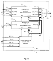
- Figure 11 depicts the buffer memory module 25, which has an address generator 251, a multiplexer 252, a first buffer 253 and a second buffer 254.
- the address generator 251 receives control signals from the controller 20.
- the signal SBV controls the locking of the data in the memories 253 and 254.
- the signal SB indicates which sub-band is currently being processed.
- the signal ENC controls the output of the data from the memory 253 or 254 for the quantisation and entropic coding of the data.
- the signal LVL indicates which resolution level is currently being processed.
- the address generator 251 supplies a write control signal WE to the memories 253 and 254, as well as two address signals AD2 and AD3.
- the addresses are here expressed in ten bits in the memory 254 and in twelve bits for the memory 253.
- the memory 253 receives the blocks LH i,L , HL i,L and HH i,L resulting from the decomposition of the current block B i at all the decomposition levels and stores them in memory.
- the blocks are grouped together according to their analysis orientation, so as to form grouping blocks of size 32x32, which corresponds to the size of the blocks which can be processed by the module 26.
- the memory 253 has a capacity to store, for each decomposition level, three grouping blocks each containing 32x32 samples expressed in 16 bits.
- one of these blocks includes a block LH i,1
- another of these blocks includes a block HL i,1
- the last block includes a block HH i,1 .
- one of these blocks itself has four blocks LH i,2
- another of these blocks has four blocks HL i,2
- the last block has four blocks HH i,2 .
- one of these blocks itself has sixteen blocks LH i,3 , another of these blocks has sixteen blocks HL i,3 and the last block has sixteen blocks HH i,3 .
- one of these blocks itself has 64 blocks LH i,4 , another of these blocks has 64 blocks HL i,4 and the last block has 64 blocks HH i,4 .
- the memory 254 receives the block LL i,4 resulting from the decomposition of the current block B i at the last decomposition level and stores it in memory.
- the memory 254 stores as many blocks LL i,4 as necessary to form a block having a size compatible with the functioning of the module 26.
- the memory 254 has a capacity to store at least one block having 32x32 samples expressed in 16 bits.
- the memory 254 can store blocks LL i,4 to form a block with a size less than that of the grouping blocks of the higher resolution levels.
- the multiplexer 252 receives a control signal from the address generator 251 and selects one of the four blocks of size 32x32 in order to transmit it to the module 26.
- the latter effects a quantisation and an entropic coding of the data which it receives.
- Figure 12 depicts a digital signal coding method according to the invention, which is implemented in the device depicted in Figure 4, described above.
- the method is depicted in the form of an algorithm including steps E1 to E18. This method effects the filtering on four decomposition levels of an image, and the quantisation and entropic coding of the filtered data.
- Step E1 is an initialisation at which a working parameter i is initialised to 1, in order to consider the first block of the image to be processed.
- the blocks are transformed in a predetermined order.
- a working parameter L is initialised to 1, in order to consider the first resolution level of the decomposition.
- the parameter L represents the current resolution level.
- step E3 is a test for determining whether the current resolution level is the first. If the response is positive, then step E3 is followed by step E4, at which the block B i of rank i is read in the image memory 210, and is then filtered so as to form four blocks of sub-bands LL i,1 , LH i,1 , HL i,1 and HH i,1 , at the first resolution level.
- the blocks LL i,1 , HL i,1 and HH i,1 are stored in the buffer 253 of the module 25, and the block LL i,1 is stored in the buffer 240 of the module 24, as previously disclosed.
- step E5 is followed by step E5, which is similar to step E4, except for the fact that the block is read in the buffer 240.
- the block read belongs to the resolution level immediately above the current level.
- the block LL i,4 is stored in the memory 254 of the module 25.
- Steps E4 and E5 are both followed by step E7, at which the parameter L is incremented by one unit in order to consider the following resolution level.
- Step E7 is followed by step E8, which is a test for determining whether the parameter L is strictly greater than 4. If the response is negative, then step E8 is followed by step E3.
- This looping makes it possible to filter a block B i at all the desired resolution levels, here four levels.
- Step E8 is then followed by step E9, at which the blocks LH i,1 , HL i,1 and HH i,1 obtained at the first decomposition level are quantised and then entropically coded. These blocks have the size required by the module 26.
- Step E9 is followed by step E10, which is a test for determining whether the memory 253 contains complete blocks LH2, HL2 and HH2 of size 32x32 containing respectively blocks LH i,2 , HL i,2 and HH i,2 obtained at the second resolution level.
- Complete block means a block whose size is appropriate for this block to be processed by the module 26.
- step E17 for considering a following block in the original image.
- step E17 is followed by the previously described step E2.
- step E10 If the response is positive at step E10, then this step is followed by step E11, at which the previous complete blocks are quantised and then entropically coded.
- Step E11 is followed by step E12, which is a test for determining whether the memory 253 contains complete blocks LH3, HL3 and HH3 of size 32x32 containing respectively blocks LH i,3 , HL i,3 and HH i,3 obtained at the third resolution level.
- step E17 for considering a following block in the original image.
- step E17 is followed by the previously described step E2.
- step E12 If the response is positive at step E12, then this step is followed by step E13, at which the previous complete blocks are quantised and then entropically coded.
- Step E13 is followed by step E14, which is a test for determining whether the memory 253 contains complete blocks LH4, HL4 and HH4 of size 32x32 containing respectively blocks LH i,4 , HL i,4 and HH i,4 obtained at the fourth resolution level and whether the memory 254 contains a complete block LL4 of size 32x32 containing blocks LL i,4 obtained at the fourth resolution level.
- step E17 for considering a following block in the original image.
- step E17 is followed by the previously described step E2.
- step E15 the previous complete blocks are quantised and then entropically coded.
- steps E10 to E15 depends on the number of resolution levels chosen.
- Step E15 is followed by step E16, which is a test for determining whether all the image to be coded has been processed.
- step E17 at which the parameter i is incremented by one unit in order to consider the following block in the image.
- Step E17 is followed by the previously described step E2.
- step E18 At which the buffers are emptied and any data which they may contain are quantised and coded. Coding of the image is then ended.
Landscapes
- Engineering & Computer Science (AREA)
- Physics & Mathematics (AREA)
- General Physics & Mathematics (AREA)
- Mathematical Physics (AREA)
- Theoretical Computer Science (AREA)
- Data Mining & Analysis (AREA)
- Mathematical Analysis (AREA)
- Mathematical Optimization (AREA)
- Computational Mathematics (AREA)
- Pure & Applied Mathematics (AREA)
- Signal Processing (AREA)
- Algebra (AREA)
- Databases & Information Systems (AREA)
- Software Systems (AREA)
- General Engineering & Computer Science (AREA)
- Multimedia (AREA)
- Compression Of Band Width Or Redundancy In Fax (AREA)
- Compression Or Coding Systems Of Tv Signals (AREA)
- Compression, Expansion, Code Conversion, And Decoders (AREA)
- Complex Calculations (AREA)
Abstract
The invention concerns the transformation of a digital signal in at least two
different frequency bands according to at least two different resolutions. The method
includes:
- dividing (E1, E18) the signal into first blocks (Bi) all having a same predetermined first number of samples,
- transforming (E4) each of the first blocks into a plurality of second blocks,
- grouping (E10) second blocks issuing from the transformation of different first blocks in order to form third blocks all having a same predetermined third number of samples which is at least equal to the largest of the second numbers.
Description
- The present invention concerns the transformation of a digital signal, such as digital filtering.
- Numerous digital filtering methods and devices are known. Digital signal analysis filterings are envisaged here by way of example. Amongst such filterings, wavelet transformations are more particularly envisaged.
- These filterings are generally subassemblies integrated into the coding and/or decoding assemblies. They often require a large amount of random access memory or buffer space for storing the data in the course of processing. For example, for image processing, the most conventional solutions for producing the wavelet transform consist of loading the entire image to be processed into memory and then effecting the different filtering steps. The memory space is then so large that this makes it difficult to implement such filterings in appliances such as photographic appliances, facsimile machines, printers or photocopiers for example.
- The present invention provides a method and a device for transforming a digital signal which minimises the degree to which the data being processed occupy buffer space.
- To this end, the invention proposes a method of transforming a digital signal representing a physical quantity, into signals of frequency sub-bands distributed in at least two different frequency bands and in at least two different resolutions,
characterised in that it includes steps of: - dividing the signal into first blocks all having a same predetermined first number of samples,
- transforming each of the first blocks formed at the previous step into a plurality of second blocks,
- grouping second blocks issuing from the transformation of different first blocks in order to form third blocks all having a same predetermined third number of samples which is at least equal to the largest of the second numbers.
- By virtue of the invention, the space taken up in the buffer by the data currently being processed is reduced compared with the prior art. Thus powerful filterings can be integrated in numerous appliances, without these requiring very large memories.
- According to a preferred characteristic, the transformation is a wavelet transformation.
- According to preferred and alternative characteristics, the first blocks overlap in pairs on a predetermined fourth number of samples or the first blocks are adjacent. The overlap between adjacent blocks, for example on a row and/or column, improves the quality of the reconstructed signal after processing.
- According to a preferred characteristic, the first blocks are processed in a predetermined order, such that the signal is transformed zone by zone, a zone of the signal being processed at all resolution levels before passing to a following zone. Thus the memory requirements are minimised.
- According to another preferred characteristic, the grouping of the second blocks is effected by grouping together second blocks having the same number of samples and samples selected according to the same frequency band. This is because blocks are grouped together having samples of the same nature, so that their subsequent processing is optimised.
- According to a preferred characteristic, the digital signal is an image signal. The invention applies advantageously to an image signal, which generally requires a large amount of memory space. This memory space is reduced by virtue of the invention.
- The invention also concerns a coding method which includes the characteristics set out above and has the same advantages.
- Correlatively, the invention proposes a device for transforming a digital signal representing a physical quantity, into signals of frequency sub-bands distributed according to at least two different frequency bands and according to at least two different resolutions,
characterised in that it has; - means of dividing the signal into first blocks all having a same predetermined first number of samples,
- means of transforming each of the first blocks into a plurality of second blocks,
- means of grouping second blocks issuing from the transformation of different first blocks in order to form third blocks all having a same predetermined third number of samples which is at least equal to the largest of the second numbers.
- The device has means of implementing the characteristics set out above.
- The invention also concerns a coding device, a digital appliance including the transformation or coding device or means of implementing the transformation or coding method. This digital appliance is for example a digital photographic appliance, a computer, a facsimile machine, a photocopier, a scanner or a printer.
- The advantages of the device and of the digital appliance are identical to those set out above.
- An information storage means which can be read by a computer or by a microprocessor, integrated or not into the device, possibly removable, stores a program implementing the filtering method.
- The characteristics and advantages of the present invention will emerge more clearly from a reading of a preferred embodiment illustrated by the accompanying drawings, in which:
- Figure 1 depicts schematically a data processing device according to the invention,
- Figure 2 depicts an embodiment of a data processing device according to the invention,
- Figure 3 depicts an embodiment of a data processing device according to the invention,
- Figure 4 depicts an embodiment of a coding circuit according to the invention included in the device of Figure 2,
- Figure 5 depicts a memory module included in the coding circuit of Figure 4,
- Figure 6 depicts a part of an image to be coded according to the invention.
- Figure 7 depicts a vertical filtering module included in the coding circuit of Figure 4,
- Figure 8 depicts a horizontal filtering module included in the coding circuit of Figure 4,
- Figure 9 depicts a buffer module included in the coding circuit of Figure 4,
- Figure 10 depicts data stored in the buffer module of Figure 8,
- Figure 11 depicts a buffer module included in the coding circuit of Figure 4, and
- Figure 12 depicts a data coding algorithm according to the invention.
- According to a chosen embodiment depicted in Figure 1, a data processing device according to the invention is a
data coding device 2 which has aninput 21 to which asource 1 of uncoded data is connected. - The
source 1 has for example a memory means, such as a random access memory, a hard disk, a diskette or a compact disc, for storing uncoded data, this memory means being associated with a suitable reading means for reading the data therein. A means for recording the data in the memory means can also be provided. - It will more particularly be considered hereinafter that the data to be coded are a series of digital samples representing an image IM.
- The
source 1 supplies a digital image signal SI at the input of thecoding circuit 2. The image signal SI is a series of digital words, for example bytes. Each byte value represents a pixel of the image IM, here with 256 grey levels, or black and white image. The image can be a multispectral image, for example a colour image having components in three frequency bands, of the red-green-blue or luminance and chrominance type. Each band is then processed in a similar fashion to the monospectral image. - Means 3 using coded data are connected at the
output 22 of thecoding device 2. - The user means 3 include for example coded data storage means, and/or coded data transmission means.
- The
coding device 2 includes conventionally, as from theinput 21, atransformation circuit 23, to which the present invention more particularly relates, and an example embodiment of which will be detailed hereinafter. The transformations envisaged here are decompositions into frequency sub-bands signals of the data signal, so as to effect an analysis of the signal. The analysis is performed on at least two resolution levels, the resolution of a signal being in general terms the number of samples per unit length which are used for representing the signal. - The
transformation circuit 23 is connected to aquantisation circuit 24. The quantisation circuit implements a quantisation known per se, for example a scalar quantisation, or a vector quantisation, of the coefficients, or groups of coefficients, of the frequency sub-band signals supplied by thecircuit 23. - The
circuit 24 is connected to anentropic coding circuit 25, which effects an entropic coding, for example a Huffman coding, or an arithmetic coding, of the data quantised by thecircuit 24. - The coding device can be integrated into a digital appliance, such as a computer, a printer, a facsimile machine, a scanner or a digital photographic apparatus, for example.
- With reference to Figure 2, an example of a
device 10 implementing the invention is described. - The
device 10 is here a microcomputer having acommunication bus 101 to which there are notably connected: - a
central unit 100, - a read only
memory 102, - a
random access memory 103, - a
dedicated circuit 104 implementing the invention, which will be described hereinafter, - an input/
output circuit 105. - The
device 10 can include, in a conventional fashion, a keyboard or a disk drive adapted to receive a diskette, or can be adapted to communicate with a communication network. - The
device 10 can receive data to be coded from a peripheral device, such as a digital photographic apparatus, or a scanner, or any other means of acquiring or storing data. - The
device 10 can also receive data to be coded from a distant device, via the communication network, and transmit coded data to a distant device, again via the communication network. - According to the embodiment depicted, the
random access memory 103 is a direct-access dynamic memory, known as DRAM, from the English "Dynamic Random Access Memory". This memory is useful in the context of the invention for reading the samples of the image in a particular order, as disclosed below. - The
circuit 104 also has a Static Random Access Memory known as SRAM. - In more general terms, the programs according to the present invention are stored in a storage means. This storage means can be read by a computer or by a microprocessor. This storage means is integrated or not into the device, and may be removable. For example, it may have a magnetic tape, a diskette or a CD-ROM (fixed-memory compact disc).
- With reference to Figure 3, there is described an example of a
device 300 implementing the invention. This device is adapted to code and/or decode a digital signal. - The
device 300 is here a microcomputer having acommunication bus 301 to which there are connected: - a
central unit 305, - a read only
memory 302, - a
random access memory 303, - a
screen 304, - a
keyboard 314, - a
hard disk 308, - a
disk drive 309 adapted to receive adiskette 310, - an
interface 312 for communication with acommunication network 313, - an input/
output card 306 connected to amicrophone 311. - The
hard disk 308 stores the programs implementing the invention, which will be described hereinafter, as well as the data to be coded and the data coded according to the invention. These programs can also be read on thediskette 310, or received via thecommunication network 313, or stored in the read onlymemory 302. - In more general terms, the programs according to the present invention are stored in a storage means. This storage means can be read by a computer or by a microprocessor. This storage means is integrated or not into the device, and may be removable. For example, it may have a magnetic tape, a diskette or a CD-ROM (fixed-memory compact disc).
- When the device is powered up, the programs according to the present invention are transferred into the
random access memory 303, which then contains the executable code of the invention, and registers containing the variables necessary for implementing the invention. These variables, which will be detailed below, are notably the variables i and L. The random access memory includes a buffer. - The
device 300 can receive data to be coded from aperipheral device 307, such as a digital photographic apparatus, or a scanner, or any other means of acquiring or storing data. - The
device 300 can also receive data to be coded from a distant device, via thecommunication network 313, and transmit coded data to a distant device, again via thecommunication network 313. - The
device 300 can also receive data to be coded from themicrophone 311. These data are then a sound signal. - The
screen 304 enables a user notably to display the data to be coded, and serves, with thekeyboard 314, as a user interface. - Figure 4 depicts an embodiment of the
coding circuit 104 according to the invention. - The
circuit 104 includes: - a
controller 20 which controls the operation of the modules included in thecircuit 104, - a reorganisation
buffer memory module 21, - a
vertical filtering module 22, - a
horizontal filtering module 23, - a first
buffer memory module 24, - a second
buffer memory module 25, - an entropic coding and
quantisation module 26. - The
module 21 has data inputs and address outputs connected to therandom access memory 103. Themodule 21 also has outputs connected to thevertical filtering module 22. Themodule 21 makes it possible to sequence the samples to be processed in a specific order and to store them before they are processed. - The
vertical filtering module 22 effects a filtering in the vertical direction of the image and has outputs connected to thehorizontal filtering module 23. - The
horizontal filtering module 23 effects a filtering in the horizontal direction of the image and has outputs connected to themodules - The
module 24 has an output connected to thevertical filtering module 22. Themodule 25 has outputs connected to the quantisation andentropic coding module 26. - The quantisation and entropic coding are conventional and will not be detailed here.
- The
modules - The operation of the
circuit 104 is approximately as follows. - The filtering is effected by blocks of samples. In general terms, a block is a group of samples selected in the image. The blocks are here rectangular in shape, with an overlap between adjacent blocks which is zero or one row and/or one column of samples. All the blocks have the same number of samples, so that they are all filtered in an identical fashion.
- For this, the samples of the image to be coded are read in the
memory 103 in a fashion sequenced by themodule 21, in the form of blocks which are then filtered in the two vertical and horizontal directions by themodules modules - The analysis is then carried out on at least two resolution levels, that is to say the sub-blocks containing samples of low frequency in the two analysis directions, obtained at at least one first resolution level, are filtered in their turn by the
modules - The sub-blocks which do not contain samples of low frequency in the two analysis directions obtained at the first resolution level are supplied to the
module 25 and are then quantised and coded entropically by themodule 26. The latter is adapted to process blocks of fixed predetermined size, chosen so as to be equal to that of the sub-blocks obtained at the first resolution level. - The blocks obtained at the lower resolution levels have sizes smaller than that required by the
module 26. These blocks are consequently grouped so as to form blocks having the required size. - The sub-blocks containing samples of low frequency in the two analysis directions are supplied to the
module 24, in order to effect the looping mentioned above, except for the last resolution level of the decomposition, where the sub-blocks are supplied to themodule 25. - Figure 5 depicts the
buffer memory module 21 for reorganising data in it. Thecircuit 21 makes it possible to read the data in an order predetermined in the original image. - For example, Figure 6 depicts part of the image to be coded. The filtering of the image is effected by blocks. Consequently the image is divided into blocks of samples Bi, where i is an integer which represents the rank of the block. By way of example, square blocks of size 64x64 samples are considered hereinafter. In addition, these blocks can overlap between adjacent blocks over a predetermined number of rows and/or over a predetermined number of columns. Hereinafter, the case will be dealt with where the overlap is of one row and one column, although larger overlaps are possible. Each block then includes (64(+1))x(64(+1)) samples. The advantage of the overlap between the adjacent blocks, and the questions of edge filtering, are disclosed in French patent applications 99 02303 and 99 02305.
- Within a block, the samples are read in a predetermined order, for example in a zigzag scanning from the top left-hand corner to the bottom righthand corner.
- The blocks are themselves processed in an ordered fashion, in an order which minimises the memory occupation of the data currently being processed.
- For example, for a decomposition of the image on three resolution levels, the blocks are considered and processed by groups of four adjacent blocks, such as the blocks B1, B2, B3 and B4.
- The groups of four blocks are themselves considered in subgroups of four blocks, referred to as macroblocks.
- The order of processing of the blocks for a decomposition of three resolution levels is depicted in Figure 6 by a continuous line. The four blocks in a group are run through before passing to the following group. Likewise, a macroblock is totally run through before passing to the following macroblock. It should be noted that, within a group of four blocks, the blocks are processed in any order. Likewise, within a macroblock, the groups are processed in any order.
- This order of processing makes it possible to filter the image by zones, at all resolution levels. Thus only the data of the current zone are kept in memory, and are filtered at all the required resolution levels.
- It should be noted that the number of blocks included in a macroblock depends on the number of resolution levels. Thus one macroblock has 16 blocks for three resolution levels, 64 blocks for four resolution levels and 256 blocks for five resolution levels.
- With reference once again to Figure 5, the
module 21 has arandom access memory 210 and a reorderedaddress generator 211. - The
address generator 211 is controlled by the signals Hsync, Vsync and ACT supplied by thecontroller 20. Theaddress generator 211 supplies an address signal ADR in seven bits to therandom access memory 210 and controls the writing of the data in this memory by the signal WE. - The
address generator 211 supplies an address signal ADR1 to therandom access memory 103 and control signals D1 and D2. The data are read in thememory 103 in series of 64(+1) bytes. - The data are written in the
memory 210 in accordance with a reading-modification-writing scheme. Thememory 210 has five inputs DI1 to DI5 and five outputs DO1 to DO5. The input DI1 receives eight bits from thememory 103. The outputs DO1 to DO4 are respectively connected to the inputs DI2 to DI5. Thememory 210 is thus a shift register having a depth of five bytes and a width of 64(+1) bytes. - The
memory 210 supplies five bytes at a time to thevertical filtering module 22. - With reference to Figure 7, the vertical filtering module has a
multiplexer 220 and avertical filtering circuit 221. - A first input of the
multiplexer 220 is connected to themodule 21 whilst the second input of themultiplexer 220 is connected to themodule 24, which will be described below. An output of themultiplexer 220 is connected to an input of thefiltering circuit 221. - The
controller 20 supplies a control signal NIV in order to indicate which is the resolution level of the data to be filtered. When the data of the original image are to be filtered, which corresponds to the highest resolution level, the multiplexer selects the data coming from themodule 21. In this case, the five bytes are thus formed into five words each of sixteen bits, setting the unused bits to zero. Thus the format of the data to be filtered is compatible with the functioning of thecircuit 221. - When data of a lower resolution level are to be filtered, the selected data are those coming from the
module 24. These data are received in the form of five words each of sixteen bits. - The
circuit 221 receives as an input five words each of sixteen bits and effects a wavelet filtering in so-called "lifting" form, as described for example in French patent application No 98 08824. The filter used here is a 5/3 filter. Other methods of effecting wavelet filtering are possible, for example by convolution. Thecircuit 221 supplies to themodule 23 two flows each of sixteen bits, one of which includes low-frequency samples and the other high-frequency samples. - Figure 8 depicts the
horizontal filtering module 23 which has twoshift registers filtering circuits - The
shift register 230 receives the high-frequency samples from themodule 22, forms five words each of 16 bits and applies them to thefiltering circuit 232. The latter, similar to thefiltering circuit 221, works here on 80 input bits and effects a wavelet filtering in the horizontal direction and supplies as an output two flows each of 16 bits. - One of these flows has samples of high frequency in the two analysis directions and the other samples of high frequency in the vertical direction and samples of low frequency in the horizontal direction.
- In a similar fashion, the
shift register 231 receives the low-frequency samples from themodule 22, forms five words each of 16 bits and applies them to thefiltering circuit 233. The latter, similar to thefiltering circuit 232, works here on 80 input bits and effects a wavelet filtering in the horizontal direction and supplies as an output two flows each of 16 bits. - One of these flows includes samples of low frequency in the two analysis directions and the other samples of low frequency in the vertical direction and samples of high frequency in the horizontal direction.
- The
module 23 thus has four outputs connected to four inputs of thememory module 25. The outputs supplying the flow of samples of low frequency in the two analysis directions is also connected to thememory module 24. - The filtering of a block Bi, of size of (64(+1))x(64(+1)) samples thus results, at the first decomposition level, in four blocks LLi,1, LHi,1, HLi,1 and HHi,1. The block LLi,1 has a size of (32(+1))x(32(+1)) samples, whilst the blocks LHi,1, HLi,1 and HHi,1 each have a size of 32x32 samples.
- The block LLi,1 contains samples of low frequency in the two analysis directions, the block LHi,1 contains samples of high frequency in a first analysis direction and of low frequency in the other analysis direction, the block HLi,1 contains samples of low frequency in the first analysis direction and of high frequency in the other analysis direction and the block HHi,1 contains samples of high frequency in the two analysis directions.
- When the block LLi,1 is in its turn filtered, this gives four blocks LLi,2, LHi,2, HLi,2 and HHi,2 at the second resolution level. The block LLi,2 has a size of (16(+1))x(16(+1)) samples and the blocks LHi,2, HLi,2 and HHi,2 each have a size of 16 x 16 samples.
- The block LLi,2 can in its turn be filtered, and so on.
- The blocks which contain samples of low frequency in one analysis direction have, at each decomposition level, an overlap in this analysis direction which is divided by two compared with the previous level, and then rounded up. The blocks which contain samples of high frequency in one analysis direction have, at each decomposition level, an overlap in this analysis direction which is divided by two compared with the previous level, and then rounded down. The overlap of the blocks which contain samples of high frequency in at least one analysis direction is eliminated. The overlap of the blocks which contain samples of low frequency in the two analysis directions is eliminated only at the end of the last decomposition level.
- Figure 9 depicts the
buffer memory module 24, which has abuffer memory 240, anaddress generator 241 and acircular shift register 242. - The
address generator 241 receives control signals from thecontroller 20. The signal PBV indicates that the data on the input bus are valid. The signal PS indicates which resolution level is currently being processed. - The
address generator 241 supplies a write control signal WE to thememory 240, and an address signal AD1. The addresses are here expressed in nine bits. - The
memory 240 receives the low-frequency sub-bands resulting from the decomposition of the blocks by thefiltering modules - Figure 10 illustrates the organisation of the
memory 240. For a decomposition at four levels of a block Bi, thememory 240 contains three areas for storing the low-frequency sub-bands LLi,1, LLi,2 and LLi,3 resulting from the decomposition of the blocks by thefiltering modules - Thus a first area has the capacity to store the block LLi,1 containing the samples of low frequency at the first resolution level, that is to say (32(+1))x(32(+1)) samples. A second area has the capacity to store the block LLi,2 containing the samples of low frequency at the second resolution level, that is to say (16(+1))x(16(+1)) samples. Finally, a third area has the capacity to store the block LLi,3 containing the samples of low frequency at the third resolution level, that is to say (8(+1))x(8(+1)). All the samples are expressed in sixteen bits.
- It is not necessary to store in the
memory 240 the block containing the samples of low frequency at the fourth and last resolution level, since this block is directly quantised and coded entropically. - As a variant, the
memory 240 can have a smaller size. This is because, after the filtering of the block LLi,1 in order to supply the block LLi,2, the blocks LLi,1 is no longer necessary. The block LLi,2 can therefore be written in place of the block LLi,1. Likewise, after the filtering of the block LLi,2 in order to supply the block LLi,3 the block LLi,2 is no longer necessary. The block LLi,3 can therefore be written in place of the block LLi,2. In this case, thememory 240 has the capacity to store the largest of the blocks LLi,1, LLi,2 and LLi,3. - Figure 11 depicts the
buffer memory module 25, which has anaddress generator 251, amultiplexer 252, afirst buffer 253 and asecond buffer 254. - The
address generator 251 receives control signals from thecontroller 20. The signal SBV controls the locking of the data in thememories memory - The
address generator 251 supplies a write control signal WE to thememories memory 254 and in twelve bits for thememory 253. - The
memory 253 receives the blocks LHi,L, HLi,L and HHi,L resulting from the decomposition of the current block Bi at all the decomposition levels and stores them in memory. The blocks are grouped together according to their analysis orientation, so as to form grouping blocks of size 32x32, which corresponds to the size of the blocks which can be processed by themodule 26. - For this, according to the example chosen, the
memory 253 has a capacity to store, for each decomposition level, three grouping blocks each containing 32x32 samples expressed in 16 bits. For the first decomposition level, one of these blocks includes a block LHi,1, another of these blocks includes a block HLi,1 and the last block includes a block HHi,1. For the second decomposition level, one of these blocks itself has four blocks LHi,2, another of these blocks has four blocks HLi,2 and the last block has four blocks HHi,2. For the third decomposition level, one of these blocks itself has sixteen blocks LHi,3, another of these blocks has sixteen blocks HLi,3 and the last block has sixteen blocks HHi,3. Finally, for the fourth decomposition level, one of these blocks itself has 64 blocks LHi,4, another of these blocks has 64 blocks HLi,4 and the last block has 64 blocks HHi,4. - The
memory 254 receives the block LLi,4 resulting from the decomposition of the current block Bi at the last decomposition level and stores it in memory. Thememory 254 stores as many blocks LLi,4 as necessary to form a block having a size compatible with the functioning of themodule 26. For this, according to the example chosen, thememory 254 has a capacity to store at least one block having 32x32 samples expressed in 16 bits. - As a variant, the
memory 254 can store blocks LLi,4 to form a block with a size less than that of the grouping blocks of the higher resolution levels. - As an output, the
multiplexer 252 receives a control signal from theaddress generator 251 and selects one of the four blocks of size 32x32 in order to transmit it to themodule 26. The latter effects a quantisation and an entropic coding of the data which it receives. - Figure 12 depicts a digital signal coding method according to the invention, which is implemented in the device depicted in Figure 4, described above. The method is depicted in the form of an algorithm including steps E1 to E18. This method effects the filtering on four decomposition levels of an image, and the quantisation and entropic coding of the filtered data.
- Step E1 is an initialisation at which a working parameter i is initialised to 1, in order to consider the first block of the image to be processed. The blocks are transformed in a predetermined order.
- At the following step E2, a working parameter L is initialised to 1, in order to consider the first resolution level of the decomposition. The parameter L represents the current resolution level.
- The following step E3 is a test for determining whether the current resolution level is the first. If the response is positive, then step E3 is followed by step E4, at which the block Bi of rank i is read in the
image memory 210, and is then filtered so as to form four blocks of sub-bands LLi,1, LHi,1, HLi,1 and HHi,1, at the first resolution level. The blocks LLi,1, HLi,1 and HHi,1 are stored in thebuffer 253 of themodule 25, and the block LLi,1 is stored in thebuffer 240 of themodule 24, as previously disclosed. - If the response is negative at step E3, then this step is followed by step E5, which is similar to step E4, except for the fact that the block is read in the
buffer 240. The block read belongs to the resolution level immediately above the current level. At the last decomposition level, the block LLi,4 is stored in thememory 254 of themodule 25. - Steps E4 and E5 are both followed by step E7, at which the parameter L is incremented by one unit in order to consider the following resolution level.
- Step E7 is followed by step E8, which is a test for determining whether the parameter L is strictly greater than 4. If the response is negative, then step E8 is followed by step E3.
- This looping makes it possible to filter a block Bi at all the desired resolution levels, here four levels.
- If the response is positive at step E8, then this means that the current block has been decomposed at all the resolution levels. Step E8 is then followed by step E9, at which the blocks LHi,1, HLi,1 and HHi,1 obtained at the first decomposition level are quantised and then entropically coded. These blocks have the size required by the
module 26. These operations are conventional and will not be described here. - Step E9 is followed by step E10, which is a test for determining whether the
memory 253 contains complete blocks LH2, HL2 and HH2 of size 32x32 containing respectively blocks LHi,2, HLi,2 and HHi,2 obtained at the second resolution level. Complete block means a block whose size is appropriate for this block to be processed by themodule 26. - If the response is negative, then the step is followed by step E17 for considering a following block in the original image. Step E17 is followed by the previously described step E2.
- If the response is positive at step E10, then this step is followed by step E11, at which the previous complete blocks are quantised and then entropically coded.
- Step E11 is followed by step E12, which is a test for determining whether the
memory 253 contains complete blocks LH3, HL3 and HH3 of size 32x32 containing respectively blocks LHi,3, HLi,3 and HHi,3 obtained at the third resolution level. - If the response is negative, then this step is followed by step E17 for considering a following block in the original image. Step E17 is followed by the previously described step E2.
- If the response is positive at step E12, then this step is followed by step E13, at which the previous complete blocks are quantised and then entropically coded.
- Step E13 is followed by step E14, which is a test for determining whether the
memory 253 contains complete blocks LH4, HL4 and HH4 of size 32x32 containing respectively blocks LHi,4, HLi,4 and HHi,4 obtained at the fourth resolution level and whether thememory 254 contains a complete block LL4 of size 32x32 containing blocks LLi,4 obtained at the fourth resolution level. - If the response is negative, then this step is followed by step E17 for considering a following block in the original image. Step E17 is followed by the previously described step E2.
- If the response is positive at step E14, then this step is followed by step E15, at which the previous complete blocks are quantised and then entropically coded.
- Naturally, the number of steps such as the steps E10 to E15 depends on the number of resolution levels chosen.
- Step E15 is followed by step E16, which is a test for determining whether all the image to be coded has been processed.
- If the response is negative, then the step is followed by step E17, at which the parameter i is incremented by one unit in order to consider the following block in the image. Step E17 is followed by the previously described step E2.
- When the response is positive at step E16, this step is followed by step E18, at which the buffers are emptied and any data which they may contain are quantised and coded. Coding of the image is then ended.
- Naturally, the present invention is in no way limited to the embodiments described and depicted, but quite the contrary encompasses any variant within the capability of a person skilled in the art.
Claims (31)
- Method of transforming a digital signal representing a physical quantity, into signals of frequency sub-bands distributed in at least two different frequency bands and in at least two different resolutions,
characterised in that it includes steps of:any second block under consideration having a second respective number of samples which depends on the resolution of the second block under consideration, and containing samples selected according to their frequency,dividing (E1, E18) the signal into first blocks (Bi) all having a same predetermined first number of samples,transforming (E4) each of the first blocks formed at the previous step into a plurality of second blocks,grouping second blocks issuing from the transformation of different first blocks in order to form third blocks all having a same predetermined third number of samples which is at least equal to the largest of the second numbers. - Transformation method according to Claim 1, characterised in that the transformation is a wavelet transformation.
- Transformation method according to Claim 1 or 2, characterised in that the first blocks (Bi) overlap in pairs on a fourth predetermined number of samples.
- Transformation method according to Claim 1 or 2, characterised in that the first blocks (Bi) are adjacent.
- Transformation method according to any one of Claims 1 to 4, characterised in that the first blocks are processed in a predetermined order, such that the signal is transformed zone by zone, a zone of the signal being processed at all the resolution levels before passing to a following zone.
- Transformation method according to any one of Claims 1 to 5, characterised in that the grouping of the second blocks is effected by grouping together second blocks having the same number of samples and samples selected according to the same frequency band.
- Method of coding a digital signal representing a physical quantity, into signals of frequency sub-bands distributed in at least two different frequency bands and in at least two different resolutions,
characterised in that it includes steps of:any second block under consideration having a second respective number of samples which depends on the resolution of the second block under consideration, and containing samples selected according to their frequency,dividing the signal into first blocks (Bi) all having a same predetermined first number of samples,transforming (E4) each of the first blocks formed at the previous step into a plurality of second blocks,grouping second blocks issuing from the transformation of different first blocks in order to form third blocks all having a same predetermined third number of samples which is at least equal to the largest of the second numbers. - Coding method according to Claim 7, characterised in that the transformation is a wavelet transformation.
- Coding method according to Claim 7 or 8, characterised in that the first blocks (Bi) overlap in pairs on a fourth predetermined number of samples.
- Coding method according to Claim 7 or 8, characterised in that the first blocks (Bi) are adjacent.
- Coding method according to any one of Claims 7 to 10, characterised in that the first blocks (Bi) are processed in a predetermined order, such that the signal is transformed zone by zone, a zone of the signal being processed at all the resolution levels before passing to a following zone.
- Coding method according to any one of Claims 7 to 11, characterised in that the grouping of the second blocks is effected by grouping together second blocks having the same number of samples and samples selected according to the same frequency band.
- Coding method according to any one of Claims 7 to 12, characterised in that it includes steps (E9, E11, E13, E15, E18) of quantisation and entropic coding of the transformed signal.
- Method according to any one of Claims 1 to 13, characterised in that the digital signal is an image signal.
- Device for transforming a digital signal representing a physical quantity, into signals of frequency sub-bands distributed according to at least two different frequency bands and according to at least two different resolutions,
characterised in that it has:any second block under consideration having a second respective number of samples which depends on the resolution of the second block under consideration, and containing samples selected according to their frequency,means of dividing the signal into first blocks (Bi) all having a same predetermined first number of samples,means of transforming (22, 23) each of the first blocks into a plurality of second blocks,means of grouping (25) second blocks issuing from the transformation of different first blocks in order to form third blocks all having a same predetermined third number of samples which is at least equal to the largest of the second numbers. - Transformation device according to Claim 15, characterised in that the transformation means are adapted to implement a wavelet transformation.
- Transformation device according to Claim 15 or 16, characterised in that the division means are adapted to form first blocks which overlap in pairs on a fourth predetermined number of samples.
- Transformation device according to Claim 15 or 16, characterised in that the division means are adapted to form first blocks which are adjacent.
- Transformation device according to any one of Claims 15 to 18, characterised in that it is adapted to process the first blocks in a predetermined order, such that the signal is transformed zone by zone, a zone of the signal being processed at all the resolution levels before passing to a following zone.
- Transformation device according to any one of Claims 15 to 19, characterised in that the grouping means are adapted to group together second blocks having the same number of samples and samples selected according to the same frequency band.
- Device for coding a digital signal representing a physical quantity, into signals of frequency sub-bands distributed according to at least two different frequency bands and according to at least two different resolutions,
characterised in that it has;any second block under consideration having a second respective number of samples which depends on the resolution of the second block under consideration, and containing samples selected according to their frequency,means of dividing the signal into first blocks (Bi) all having a same predetermined first number of samples,means of transforming (22, 23) each of the first blocks formed at the previous step into a plurality of second blocks,means of grouping (25) second blocks issuing from the transformation of different first blocks in order to form third blocks all having a same predetermined third number of samples which is at least equal to the largest of the second numbers. - Coding device according to Claim 21, characterised in that the transformation means are adapted to implement a wavelet transformation.
- Coding device according to Claims 21 or 22, characterised in that the division means are adapted to form first blocks which overlap in pairs on a fourth predetermined number of samples.
- Coding device according to Claim 21 or 22, characterised in that the division means are adapted to form first blocks which are adjacent.
- Coding device according to any one of Claims 21 to 24, characterised in that it is adapted to process the first blocks in a predetermined order, such that the signal is transformed zone by zone, a zone of the signal being processed at all the resolution levels before passing to a following zone.
- Coding device according to any one of Claims 21 to 25, characterised in that the grouping means are adapted to group together second blocks having the same number of samples and samples selected according to the same frequency band.
- Coding device according to any one of Claims 21 to 26, characterised in that it has means (26) for the quantisation and entropic coding of the transformed signal.
- Device according to any one of Claims 15 to 27, characterised in that it is adapted to process a digital signal which is an image signal.
- Device according to any one of Claims 15 to 28, characterised in that the division, transformation and grouping means are incorporated in:a controller (20),a read only memory containing a program for coding each of the blocks of data, anda random access memory containing registers adapted to record variables modified during the running of said program.
- Digital apparatus (10) including means of implementing the transformation method according to any one of Claims 1 to 14.
- Digital apparatus (10) including the device according to any one of Claims 15 to 29.
Applications Claiming Priority (2)
| Application Number | Priority Date | Filing Date | Title |
|---|---|---|---|
| FR9904747 | 1999-04-15 | ||
| FR9904747A FR2792433A1 (en) | 1999-04-15 | 1999-04-15 | DIGITAL SIGNAL TRANSFORMATION DEVICE AND METHOD |
Publications (1)
| Publication Number | Publication Date |
|---|---|
| EP1045309A1 true EP1045309A1 (en) | 2000-10-18 |
Family
ID=9544455
Family Applications (1)
| Application Number | Title | Priority Date | Filing Date |
|---|---|---|---|
| EP00400900A Withdrawn EP1045309A1 (en) | 1999-04-15 | 2000-03-31 | Wavelet transform method and apparatus |
Country Status (4)
| Country | Link |
|---|---|
| US (1) | US6891895B1 (en) |
| EP (1) | EP1045309A1 (en) |
| JP (1) | JP4536868B2 (en) |
| FR (1) | FR2792433A1 (en) |
Families Citing this family (21)
| Publication number | Priority date | Publication date | Assignee | Title |
|---|---|---|---|---|
| JP4700838B2 (en) * | 2001-05-21 | 2011-06-15 | キヤノン株式会社 | Filter processing device |
| US7580578B1 (en) | 2003-02-03 | 2009-08-25 | Canon Kabushiki Kaisha | Method and device for forming a compressed transcoded digital image signal |
| FR2889004B1 (en) * | 2005-07-22 | 2007-08-24 | Canon Kk | METHOD AND DEVICE FOR PROCESSING A SEQUENCE OF DIGITAL IMAGES WITH SPATIAL SCALABILITY OR QUALITY |
| FR2896371B1 (en) | 2006-01-19 | 2008-11-07 | Canon Kk | METHOD AND DEVICE FOR PROCESSING A SEQUENCE OF DIGITAL IMAGES WITH AN EXTENDABLE FORMAT |
| JP4182446B2 (en) * | 2006-07-14 | 2008-11-19 | ソニー株式会社 | Information processing apparatus and method, program, and recording medium |
| JP4182447B2 (en) * | 2006-07-14 | 2008-11-19 | ソニー株式会社 | Information processing apparatus and method, program, and recording medium |
| FR2907575B1 (en) * | 2006-10-18 | 2009-02-13 | Canon Res Ct France Soc Par Ac | METHOD AND DEVICE FOR ENCODING IMAGES REPRESENTING VIEWS OF THE SAME SCENE |
| AU2006246497B2 (en) * | 2006-11-30 | 2010-02-11 | Canon Kabushiki Kaisha | Method and apparatus for hybrid image compression |
| FR2909474B1 (en) * | 2006-12-04 | 2009-05-15 | Canon Kk | METHOD AND DEVICE FOR ENCODING DIGITAL IMAGES AND METHOD AND DEVICE FOR DECODING CODE DIGITAL IMAGES |
| FR2931025B1 (en) * | 2008-05-07 | 2010-05-21 | Canon Kk | METHOD FOR DETERMINING PRIORITY ATTRIBUTES ASSOCIATED WITH DATA CONTAINERS, FOR EXAMPLE IN A VIDEO STREAM, CODING METHOD, COMPUTER PROGRAM AND ASSOCIATED DEVICES |
| FR2931610B1 (en) * | 2008-05-20 | 2010-12-17 | Canon Kk | METHOD AND DEVICE FOR TRANSMITTING IMAGE DATA |
| FR2932637B1 (en) * | 2008-06-17 | 2010-08-20 | Canon Kk | METHOD AND DEVICE FOR ENCODING AN IMAGE SEQUENCE |
| FR2939593B1 (en) * | 2008-12-09 | 2010-12-31 | Canon Kk | VIDEO ENCODING METHOD AND DEVICE |
| EP2257073A1 (en) * | 2009-05-25 | 2010-12-01 | Canon Kabushiki Kaisha | Method and device for transmitting video data |
| EP2265026A1 (en) * | 2009-06-16 | 2010-12-22 | Canon Kabushiki Kaisha | Method and device for deblocking filtering of SVC type video streams during decoding |
| EP2285122B1 (en) * | 2009-07-17 | 2013-11-13 | Canon Kabushiki Kaisha | A method and device for reconstructing a sequence of video data after transmission over a network |
| EP2285112A1 (en) * | 2009-08-07 | 2011-02-16 | Canon Kabushiki Kaisha | Method for sending compressed data representing a digital image and corresponding device |
| FR2951345B1 (en) | 2009-10-13 | 2013-11-22 | Canon Kk | METHOD AND DEVICE FOR PROCESSING A VIDEO SEQUENCE |
| FR2955995B1 (en) * | 2010-02-04 | 2012-02-17 | Canon Kk | METHOD AND DEVICE FOR PROCESSING A VIDEO SEQUENCE |
| EP3499885B1 (en) | 2017-12-18 | 2024-07-17 | Canon Kabushiki Kaisha | Method and device for encoding video data |
| EP3499886B1 (en) | 2017-12-18 | 2025-02-12 | Canon Kabushiki Kaisha | Method and device for encoding video data |
Citations (2)
| Publication number | Priority date | Publication date | Assignee | Title |
|---|---|---|---|---|
| WO1997016028A1 (en) * | 1995-10-25 | 1997-05-01 | Sarnoff Corporation | Overlapping block zerotree wavelet image coder |
| WO1997018527A1 (en) * | 1995-11-14 | 1997-05-22 | The Regents Of The University Of California | Storage and retrieval of large digital images |
Family Cites Families (10)
| Publication number | Priority date | Publication date | Assignee | Title |
|---|---|---|---|---|
| JP2861373B2 (en) * | 1990-11-16 | 1999-02-24 | ソニー株式会社 | Apparatus and method for receiving encoded data |
| US5809201A (en) * | 1994-06-24 | 1998-09-15 | Mitsubishi Denki Kabushiki Kaisha | Specially formatted optical disk and method of playback |
| JP3534465B2 (en) * | 1994-12-28 | 2004-06-07 | パイオニア株式会社 | Subband coding method |
| US5822373A (en) * | 1995-08-17 | 1998-10-13 | Pittway Corporation | Method and apparatus for optimization of wireless communications |
| US6483946B1 (en) * | 1995-10-25 | 2002-11-19 | Sarnoff Corporation | Apparatus and method for encoding zerotrees generated by a wavelet-based coding technique |
| JP3213561B2 (en) * | 1997-02-05 | 2001-10-02 | シャープ株式会社 | Image encoding device and image decoding device |
| US6501860B1 (en) * | 1998-01-19 | 2002-12-31 | Canon Kabushiki Kaisha | Digital signal coding and decoding based on subbands |
| KR100284027B1 (en) * | 1998-12-22 | 2001-03-02 | 서평원 | Repositioning Wavelet Packet Counts |
| US6760482B1 (en) * | 1999-02-19 | 2004-07-06 | Unisearch Limited | Method for visual optimisation of embedded block codes to exploit visual masking phenomena |
| US6505299B1 (en) * | 1999-03-01 | 2003-01-07 | Sharp Laboratories Of America, Inc. | Digital image scrambling for image coding systems |
-
1999
- 1999-04-15 FR FR9904747A patent/FR2792433A1/en active Pending
-
2000
- 2000-03-31 EP EP00400900A patent/EP1045309A1/en not_active Withdrawn
- 2000-04-04 US US09/542,920 patent/US6891895B1/en not_active Expired - Fee Related
- 2000-04-17 JP JP2000115652A patent/JP4536868B2/en not_active Expired - Fee Related
Patent Citations (2)
| Publication number | Priority date | Publication date | Assignee | Title |
|---|---|---|---|---|
| WO1997016028A1 (en) * | 1995-10-25 | 1997-05-01 | Sarnoff Corporation | Overlapping block zerotree wavelet image coder |
| WO1997018527A1 (en) * | 1995-11-14 | 1997-05-22 | The Regents Of The University Of California | Storage and retrieval of large digital images |
Non-Patent Citations (1)
| Title |
|---|
| CHRYSAFIS C ET AL: "Line based reduced memory, wavelet image compression", DATA COMPRESSION CONFERENCE,US,IEEE COMPUTER SOCIETY PRESS, LOS ALAMITOS, CA, April 1998 (1998-04-01), pages 398 - 407-407, XP002113225 * |
Also Published As
| Publication number | Publication date |
|---|---|
| JP2000341693A (en) | 2000-12-08 |
| US6891895B1 (en) | 2005-05-10 |
| JP4536868B2 (en) | 2010-09-01 |
| FR2792433A1 (en) | 2000-10-20 |
Similar Documents
| Publication | Publication Date | Title |
|---|---|---|
| US6891895B1 (en) | Device and method for transforming a digital signal | |
| US7190838B2 (en) | Method and device for processing a coded digital signal | |
| US5189526A (en) | Method and apparatus for performing image compression using discrete cosine transform | |
| EP1148731B1 (en) | Moving picture decoding apparatus, control method therefor, and storage medium | |
| DE69230922T2 (en) | Video signal encoder with block exchange technology | |
| EP1730964B1 (en) | Video coding system providing separate coding chains for dynamically selected small-size or full-size playback | |
| US7382923B2 (en) | Method and device for processing and decoding a coded digital signal | |
| KR950012981B1 (en) | Digital communication transmission and / or recording reproduction method and apparatus therefor | |
| US20130148889A1 (en) | Flexible data organization for images | |
| EP1009168A2 (en) | Image processing apparatus and method, and recording medium | |
| EP1032215B1 (en) | Device and method for transforming a digital signal | |
| JP4514169B2 (en) | Digital signal conversion apparatus and method | |
| JP5017555B2 (en) | Image encoding apparatus and image decoding apparatus | |
| EP0683599A1 (en) | Image processing apparatus and method | |
| US6801666B1 (en) | Device and method for transforming a digital signal | |
| CN100354892C (en) | Image edge filtering | |
| JPS5941969A (en) | Gradational image recording and processing system | |
| US7565024B2 (en) | Run length coding and decoding | |
| JP3168183B2 (en) | Data processing device | |
| JP2738136B2 (en) | Blocking device | |
| JP4678814B2 (en) | Image processing method and apparatus | |
| US8588539B2 (en) | Methods and devices for filtering and coding a digital signal | |
| JP4013721B2 (en) | Image processing device | |
| US6538766B1 (en) | Conversion of digital data into bit-map mode | |
| JP2005109776A (en) | Encoding device and decoding device |
Legal Events
| Date | Code | Title | Description |
|---|---|---|---|
| PUAI | Public reference made under article 153(3) epc to a published international application that has entered the european phase |
Free format text: ORIGINAL CODE: 0009012 |
|
| AK | Designated contracting states |
Kind code of ref document: A1 Designated state(s): AT BE CH CY DE DK ES FI FR GB GR IE IT LI LU MC NL PT SE |
|
| AX | Request for extension of the european patent |
Free format text: AL;LT;LV;MK;RO;SI |
|
| 17P | Request for examination filed |
Effective date: 20010310 |
|
| AKX | Designation fees paid |
Free format text: AT BE CH CY DE DK ES FI FR GB GR IE IT LI LU MC NL PT SE |
|
| STAA | Information on the status of an ep patent application or granted ep patent |
Free format text: STATUS: THE APPLICATION IS DEEMED TO BE WITHDRAWN |
|
| 18D | Application deemed to be withdrawn |
Effective date: 20151001 |