EP1045241A2 - Method of measuring the permeability of a material using thermogravimetric analysis techniques - Google Patents
Method of measuring the permeability of a material using thermogravimetric analysis techniques Download PDFInfo
- Publication number
- EP1045241A2 EP1045241A2 EP00302817A EP00302817A EP1045241A2 EP 1045241 A2 EP1045241 A2 EP 1045241A2 EP 00302817 A EP00302817 A EP 00302817A EP 00302817 A EP00302817 A EP 00302817A EP 1045241 A2 EP1045241 A2 EP 1045241A2
- Authority
- EP
- European Patent Office
- Prior art keywords
- receptacle
- lid
- sealed
- sheet
- permeability
- Prior art date
- Legal status (The legal status is an assumption and is not a legal conclusion. Google has not performed a legal analysis and makes no representation as to the accuracy of the status listed.)
- Withdrawn
Links
Images


Classifications
-
- G—PHYSICS
- G01—MEASURING; TESTING
- G01N—INVESTIGATING OR ANALYSING MATERIALS BY DETERMINING THEIR CHEMICAL OR PHYSICAL PROPERTIES
- G01N5/00—Analysing materials by weighing, e.g. weighing small particles separated from a gas or liquid
- G01N5/04—Analysing materials by weighing, e.g. weighing small particles separated from a gas or liquid by removing a component, e.g. by evaporation, and weighing the remainder
-
- G—PHYSICS
- G01—MEASURING; TESTING
- G01N—INVESTIGATING OR ANALYSING MATERIALS BY DETERMINING THEIR CHEMICAL OR PHYSICAL PROPERTIES
- G01N15/00—Investigating characteristics of particles; Investigating permeability, pore-volume, or surface-area of porous materials
- G01N15/08—Investigating permeability, pore-volume, or surface area of porous materials
-
- Y—GENERAL TAGGING OF NEW TECHNOLOGICAL DEVELOPMENTS; GENERAL TAGGING OF CROSS-SECTIONAL TECHNOLOGIES SPANNING OVER SEVERAL SECTIONS OF THE IPC; TECHNICAL SUBJECTS COVERED BY FORMER USPC CROSS-REFERENCE ART COLLECTIONS [XRACs] AND DIGESTS
- Y10—TECHNICAL SUBJECTS COVERED BY FORMER USPC
- Y10T—TECHNICAL SUBJECTS COVERED BY FORMER US CLASSIFICATION
- Y10T436/00—Chemistry: analytical and immunological testing
- Y10T436/25—Chemistry: analytical and immunological testing including sample preparation
Definitions
- the present invention relates generally to permeability measurements, and more particularly, to a method for measuring the permeability of materials using thermogravimetric analysis techniques.
- Some materials are permeable with respect to gases and/or liquids.
- the permeability of a material is defined as the time rate of vapor transmission through a unit area of flat material of unit thickness induced by unit vapor pressure difference between two specific surfaces under specified temperature and vapor pressure conditions.
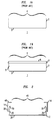
- FIG. 1A A cross-sectional view of a container 1 useful for measuring permeability via the controlled transmission method is shown in FIG. 1A.
- the container 1 includes sidewalls 2, a bottom 3, and a mouth 4.
- Container 1 is made of a material which is impermeable to liquids placed therein.
- a container made of glass is impermeable to liquids such as water and isopropyl alcohol.
- an amount of a liquid 5 is placed in the container 1, as shown in FIG. 1B.
- the mouth 4 thereof is covered with a sheet of material 6, whose permeability is to be tested.
- the material sheet 6 is attached to the container with a sealant 7.
- Suitable sealants typically include waxes such as beeswax and paraffin.
- the area of the material sheet 6 covering the mouth 4 of the container 1 defines the area available for vapor transport.
- the container 1 is weighed and placed in a controlled environment (not shown) having a specified temperature and a specified vapor pressure.
- a controlled environment not shown
- the measurement is made at a controlled humidity.
- the specified temperature is within the range of about 21 °C to about 32 °C, while the specified humidity is about 50 %.
- the weight of the container 1 is measured periodically as a function of time (e. g., once every hour for 28 days). By measuring the weight change of the container as a function of time, one determines the rate per unit area of vapor transmitted through the material sample. Based on the thickness of the material sheet as well as the difference in the vapor pressure inside the container and outside of the container, the permeability of the material sheet is computed.
- One problem with the controlled transmission method is related to the time required for determining the rate of vapor transmittance through the material sheet. Typically, for the temperature range of about 21 °C to about 32 °C, long times (on the order of days or weeks) are required for accurately determining the transmittance through the material sheet.
- Another problem with the controlled transmission method is related to the amount of liquid placed in the container.
- the weight change of the container is measured using a scale which is accurate to about ⁇ 100 mg (milligram).
- a measurement error of about ⁇ 100 mg is about 10 % of the total weight of the liquid. Consequently, such scales cannot measure the weight changes of a small amount of liquid with an accuracy that provides an acceptable measurement of the permeability.
- large containers having a mouth area greater than about 3000 mm 2 ) that are at least about 90 % filled are typically used.
- large containers require large material sheets (greater than the area of the container mouth) for sealing the mouth of the container.
- Different regions of a large material sheet potentially have different thicknesses. When different regions of the material sheet have different thicknesses, such regions have different permeation rates, thereby introducing errors into the permeability measurement.
- the weight change of the container is measured periodically as a function of time.
- the weight change of the container is measured in an environment that is not controlled (e.g., temperature and humidity). Since the weight change of the container is measured in environmental conditions that may be different from the controlled environment, a portion of such weight change is potentially attributable to transmission of the liquid through the material sample when the container is outside of the controlled environment.
- the weight change for the container is attributable to environmental conditions outside of the controlled environment, errors in measurement result.
- the present invention is directed to a method for measuring the permeability of a material using a thermogravimetric analyzer.
- the permeability of the material is measured by sealing a sheet thereof over an opening in a liquid (or solid, or gas) containing receptacle.
- the sealed receptacle is then placed in the thermogravimetric analyzer wherein the weight of such receptacle is monitored as a function of time.
- Monitoring the weight of the receptacle as a function of time using the thermogravimetric analyzer is desirable because the weight measurements are performed in a controlled environment.
- a receptacle and a receptacle lid are provided.
- the receptacle has a bottom surface and side-walls.
- the receptacle lid has a top surface and side-walls.
- the receptacle and the receptacle lid are configured so that the side-walls thereof form a seal when the receptacle lid is placed on the receptacle.
- the top surface of the receptacle lid has a hole therein.
- the hole preferably has an area that is less than about 80 % of the area of the receptacle lid. Holes with areas greater than about 80 % of the area of the receptacle lid are undesirable because such holes potentially interfere with the formation of the seal between the receptacle and the receptacle lid.
- the receptacle and the receptacle lid are made of a material which is impermeable to the liquid (or solid, or gas) placed therein.
- receptacle materials include metal or glass. Suitable metals include aluminum and stainless steel.
- a sealed receptacle is assembled by filling the receptacle with an amount of a liquid (or solid, or gas). After the receptacle is filled with the liquid (or solid, or gas), a material sheet is placed in the receptacle lid so that it covers the hole therein. The receptacle lid is than compressed onto the receptacle to form the sealed receptacle.
- the receptacle is optionally sealed with a deformable material.
- the deformable material is placed in the receptacle lid on the material sheet along the perimeter of the side-walls of the lid, prior to the lid being compressed on the receptacle.
- the deformable material preferably has the shape of an o-ring. Examples of suitable deformable materials include rubber, silicone rubber, thermoplastic elastomers, thermosets, and hydrophobic materials such as hydrocarbon waxes and Teflon.
- the top edges of the receptacle side-walls When the receptacle is sealed with the deformable material, it is desirable for the top edges of the receptacle side-walls to be bent towards the center of the receptacle. Bending the top edges of the receptacle side-walls toward the center of the receptacle facilitates the formation of the seal between the receptacle, the deformable material, and the material sheet when the receptacle lid is placed thereon.
- the top edges of the receptacle side-walls are preferably bent towards the center of the receptacle at an angle of less than about 60 degrees.
- the bent edges preferably have a length less than about 0.8 mm.
- the sealed receptacle is placed in a thermogravimetric analyzer.
- the thermogravimetric analyzer includes a chamber, and a scale.
- the chamber is configured to include one or more gas input ports, a gas output port, and a receptacle holder.
- the receptacle holder is coupled to the scale.
- the humidity (or vapor pressure, if a vapor other than water is used) in the chamber is controlled based on the vapor content and flow rates of gases input to the chamber via the one or more gas input ports. For example, a 1:1 mixture of dry nitrogen (relative humidity of about 0 %) and wet nitrogen (relative humidity of about 100 %) provides a chamber relative humidity of about 50%.
- a heater for controlling chamber temperature is optionally mounted inside the chamber proximate to the receptacle holder or on an outer surface of the chamber.
- the weight of the liquid (or solid, or gas) in the receptacle is determined. Thereafter, the weight change for the sealed receptacle is measured as a function of time.
- the present invention is directed to a method for measuring the permeability of a material using a thermogravimetric analyzer.
- the permeability of the material is measured by sealing a sheet thereof over an opening in a liquid (or solid, or gas) containing receptacle.
- the sealed receptacle is then placed in the thermogravimetric analyzer wherein the weight of such receptacle is monitored as a function of time.
- Monitoring the weight of the receptacle as a function of time using the thermogravimetric analyzer is desirable because the weight measurements are performed in a controlled environment.
- thermogravimetric analyzers measure weights with accuracies of about ⁇ 1 ⁇ g. Such an accuracy permits the determination of permeation rates with time ranges on the order of minutes to hours rather than days to weeks.
- thermogravimetric analyzer Determining the permeability of a material sheet using a thermogravimetric analyzer is also amenable to the use of material sheets with small areas (less than about 1000 mm 2 ), for which the thickness variation across the sheet area is less than that of a larger area (greater than about 3000 mm 2 ) material sheet. Small area material sheets are also desirable when the material to be tested is only available in limited quantity or where measurements are to be performed in environments with small geometries.
- a receptacle 12 and a receptacle lid 14 are provided, as shown in FIG. 2.
- the receptacle 12 has a bottom surface 20 and side-walls 25.
- the receptacle lid 14 has a top surface 40 and side-walls 35.
- the receptacle 12 and the receptacle lid 14 are configured so that the side-walls 25,35 thereof form a seal when the receptacle lid 14 is placed on the receptacle 12.
- the top surface 40 of the receptacle lid 14 preferably has an area less than about 1000 mm 2 . Such a top surface area is suitable for use with a thermogravimetric analyzer.
- the top surface 40 of the receptacle lid 14 has a hole 45 therein.
- the hole 45 has an area that is less than about 80 % of the area of the receptacle lid 14. Holes 45 with areas greater than about 80 % of the area of the receptacle lid 14 are undesirable because such holes 45 potentially interfere with the formation of the seal between the receptacle 12 and the receptacle lid 14.
- the receptacle 12 and the receptacle lid 14 are each made of a material which is impermeable to the liquids (or solids, or gases) placed therein.
- suitable materials include metals such as aluminum and stainless steel, or glass.
- Receptacles and receptacle lids (without holes) are available from Perkin-Elmer Company, Norwalk, Connecticut.
- a scaled receptacle is assembled by filling the receptacle 12 with an amount of a liquid 50 (or solid, or gas), as shown in FIG. 3. Thereafter, a material sheet 55, whose permeability is to be determined, is placed in the receptacle lid 14 so that it covers the hole 45 therein. The receptacle lid 14 is than compressed onto the receptacle 12 to form the scaled receptacle 12.
- the receptacle is optionally sealed with a deformable material 60.
- the deformable material 60 is placed in the receptacle lid 14 on the material sheet 55 along the perimeter of the side-walls 35 of the lid, before the receptacle lid 14 is compressed on the receptacle 12.
- the deformable material preferably is an o-ring. Examples of suitable deformable materials include rubber, silicone rubber, thermoplastic elastomers, thermosets, and hydrophobic materials such as hydrocarbon waxes and Teflon.
- the top edges 30 of the receptacle side-walls 25 When the receptacle 12 is sealed with the deformable material 60, it is desirable for the top edges 30 of the receptacle side-walls 25 to be bent towards the center of the receptacle 12. Bending the top edges 30 of the receptacle side-walls 25 toward the center of the receptacle 12 facilitates the formation of the seal between the receptacle 12, the deformable material 60, and the material sheet 55 when the receptacle lid 14 is placed thereon.
- the top edges 30 of the receptacle side-walls 25 are preferably bent towards the center of the receptacle 12 at an angle of less than about 60 degrees.
- the bent edges 30 preferably have a length less than about 0.8 mm.
- thermogravimetric analyzer 100 A suitable thermogravimetric analyzer 100 is shown in FIG. 4.
- the thermogravimetric analyzer 100 includes, a chamber 110 and a scale 112.
- the chamber 110 is configured to include one or more gas input ports 120, a gas output port 128, and a receptacle holder 114.
- the receptacle holder 114 is coupled to the scale 112.
- the scale 112 preferably has an accuracy of about ⁇ 1 ⁇ g (microgram).
- the humidity (or vapor pressure, if a vapor other than water is used) in the chamber 110 is controlled based on the vapor content and flow rates of gases input thereto via the one or more gas input ports 120. For example, a 1:1 mixture of dry nitrogen (relative humidity of about 0 %) and wet nitrogen (relative humidity of about 100 %) provides a chamber relative humidity of about 50 %.
- the temperature in the chamber 110 is controlled with a heater (not shown).
- the heater is optionally mounted inside the chamber proximate to the receptacle holder or on an outer surface of the chamber.
- Suitable thermal analyzers include the Thermogravimetric Analyzer TGA-7 (commercially available from Perkin-Elmer Company), TGA 2950 (commercially available from Thermal Analysis Instruments Inc.), and TG/DTA 200 (commercially available from Seiko Corp.).
- the weight of the liquid (or solid, or gas) in the receptacle is determined. Thereafter, the weight change for the sealed receptacle is measured as a function of time at a specified temperature and a specified vapor pressure.
- the weight of the receptacle decreases over time as any vapor therein is transmitted out of the receptacle into the chamber 110 of the thermogravimetric analyzer 100 through the material sheet 55 (referring to FIG. 3). Conversely, when the value for the vapor pressure is higher in the chamber 110 of the thermogravimetric analyzer 100 than in the sealed receptacle, the weight of the receptacle increases over time as vapor in the chamber 110 is transmitted into the receptacle through material sheet 55.
- the permeability (P) is calculated as where ⁇ W is the weight change for the sealed receptacle, d is the thickness of the material sheet, t is the time, A is the area of the hole in the receptacle lid, p 1 is the vapor pressure in the sealed receptacle, and p 2 is the vapor pressure in the chamber.
- the stainless steel receptacle had a height of about 2.5 mm and a diameter of about 5.5 mm.
- a 0.12 mm thick laminate of ZINTEX (0.45 ⁇ m pores on a woven nylon support) was placed over an opening in a stainless steel receptacle lid.
- the stainless steel receptacle lid had a height of about 2.3 mm and a diameter of about 5.6 mm.
- the opening in the stainless steel receptacle lid had a diameter of about 4.25 mm.
- the stainless steel receptacle and the stainless steel receptacle lid (without a hole) were obtained from Perkin-Elmer Company, Norwalk, Connecticut.
- the ZINTEX was obtained from W. R. Gore & Associates, Inc., Elkton, Maryland.
- a neoprene o-ring was placed on the ZINTEX laminate in the stainless steel receptacle lid.
- the neoprene o-ring was about 0.6 mm thick.
- the neoprene o-ring was obtained from Perkin-Elmer Company.
- the stainless steel receptacle lid was compressed onto the stainless steel receptacle using a Quick Press compression tool, commercially available from Perkin-Elmer Company.
- the sealed receptacle was placed in a Perkin-Elmer TGA-7 thermogravimetric analyzer.
- the Perkin-Elmer TGA-7 was fitted with a Perkin-Elmer high temperature external furnace.
- the water in the sealed receptacle weighed about 61.043 mg.
- the humidity in the sealed receptacle was about 100 %.
- the weight of the water in the sealed receptacle was continuously measured at a chamber temperature of about 22 °C and a chamber humidity of about 4 % for about 80 minutes. Thereafter, the weight of the water in the sealed receptacle was measured when the temperature and humidity in the chamber were increased to about 50 °C and about 35 %, respectively, for about 28 minutes.
- FIG. 5 is a graph of the weight % of the water in the sealed receptacle plotted as a function of time.
- the weight change for the water in the sealed receptacle measured at a chamber temperature of about 22 °C and humidity of about 4 % is denoted as 200.
- the weight change for the water in the sealed receptacle measured at a chamber temperature of about 50 °C and humidity of about 35 % is denoted as 210.
- FIG. 5 illustrates that at a chamber temperature of about 22 °C and humidity of about 4 %, the weight of the water in the receptacle decreased by about 0.18 % per minute. However, when the temperature and humidity were increased to about 50 °C and about 35 %, respectively, the weight of the water in the receptacle decreased by about 1.7 % per minute.
- a neoprene o-ring was placed on the SympaTex film in the receptacle lid.
- the neoprene o-ring was obtained from Perkin-Elmer Company and had the dimensions described in Example 1.
- the stainless steel receptacle lid was compressed onto the stainless steel receptacle as described in Example 1.
- the sealed receptacle was placed in the Perkin-Elmer TGA-7 described in Example 1.
- the water in the sealed receptacle weighed about 54.247 mg.
- the humidity in the sealed receptacle was about 100 %.
- the weight of the water in the sealed receptacle was continuously measured at a chamber temperature of about 22 °C and a chamber humidity of about 4 % for about 120 minutes. Thereafter, the weight of the water in the sealed receptacle was measured when the temperature and humidity in the chamber were increased to about 50 °C and about 35 %, respectively, for about 40 minutes.
- FIG. 6 is a graph of the weight % of the water in the sealed receptacle plotted as a function of time.
- the weight change for the water in the sealed receptacle measured at a chamber temperature of about 22 °C and humidity of about 4 % is denoted as 300.
- the weight change for the water in the sealed receptacle measured at a chamber temperature of about 50 °C and humidity of about 35 % is denoted as 310.
- FIG. 6 illustrates that at a chamber temperature of about 22 °C and humidity of about 4 %, the weight of the water in the receptacle decreased by about 0.25 % per minute. However, when the temperature and humidity were increased to about 50 °C and about 35 %, respectively, the weight of the water in the receptacle decreased by about 2.2 % per minute.
- a neoprene o-ring was placed on the film of cured GE Silicone RTV-615 in the receptacle lid.
- the neoprene o-ring was obtained from Perkin-Elmer Company and had the dimensions described in Example 1.
- the stainless steel receptacle lid was compressed onto the stainless steel receptacle as described in Example 1.
- the sealed receptacle was placed in the Perkin-Elmer TGA-7, described in Example 1.
- the water in the sealed receptacle weighed about 61.043 mg.
- the humidity in the sealed receptacle was about 100 %.
- the weight of the water in the sealed container was continuously measured at the temperatures and vapor pressure differences ( p 1 -p 2 ) listed in Table 1. Temperature (°C) Vapor Pressure Differences ( p 1 -p 2 )(mm Hg) Permeability (g-cm/cm 2 -sec-mm Hg) 23 21.1 5.1 x 10 -10 39 52.4 7.5 x 10 -10 48 83.7 9.8 x 10 -10 57 129.8 11.4 x 10 -10
- FIG. 7 is a graph of the weight % of the water in the sealed receptacle plotted as a function of time.
- the weight changes for the water in the sealed receptacle measured at temperatures and vapor pressure differences of about 23 °C and 21.1 mm Hg, 48 °C and 83.7 mm Hg, 39 °C and 52.4 mm Hg, and 57 °C and 129.8 mm Hg are denoted as 400, 401, 402, and 403, respectively.
- the permeability of the 0.32 mm thick film of cured GE Silicone RTV-615 was calculated using equation (1).
- the permeability for each temperature and vapor pressure difference is listed in Table 1.
- a neoprene o-ring was placed on the film of GE Lexan 141 polycarbonate in the receptacle lid.
- the neoprene o-ring was obtained from Perkin-Elmer Company and had the dimensions described in Example 1.
- the stainless steel receptacle lid was compressed onto the stainless steel receptacle as described in Example 1.
- the sealed receptacle was placed in the Perkin-Elmer TGA-7, described in Example 1.
- the water in the sealed receptacle weighed about 53.185 mg.
- the humidity in the sealed receptacle was about 100 %.
- the weight of the water in the sealed receptacle was continuously measured at a chamber temperature of about 22 °C and a chamber vapor pressure difference of about 21.1 mm Hg for about 275 minutes.
- FIG. 8 is a graph of the weight change of the water in the sealed receptacle plotted as a function of time.
Abstract
A method for measuring the permeability of a material (55) using a
thermogravimetric analyzer is disclosed. The permeability of the material is
measured by sealing a sheet (55) of such material over an opening in a liquid (50)(or solid, or
gas) filled receptacle (12). The sealed receptacle is than placed in a thermogravimetric
analyzer wherein the weight of such receptacle is monitored as a function of time in
a controlled environment.
Description
- The present invention relates generally to permeability measurements, and more particularly, to a method for measuring the permeability of materials using thermogravimetric analysis techniques.
- Some materials (e. g., plastic films, paper) are permeable with respect to gases and/or liquids. The permeability of a material is defined as the time rate of vapor transmission through a unit area of flat material of unit thickness induced by unit vapor pressure difference between two specific surfaces under specified temperature and vapor pressure conditions.
- One technique used to measure the permeability of a material is called the controlled transmission method (see American Society for Testing Materials (ASTM) Standard E96-80). A cross-sectional view of a container 1 useful for measuring permeability via the controlled transmission method is shown in FIG. 1A. The container 1 includes sidewalls 2, a bottom 3, and a mouth 4. Container 1 is made of a material which is impermeable to liquids placed therein. For example, a container made of glass is impermeable to liquids such as water and isopropyl alcohol.
- In the controlled transmission method, an amount of a liquid 5 is placed in the container 1, as shown in FIG. 1B. After the liquid 5 is placed in the container 1, the mouth 4 thereof is covered with a sheet of material 6, whose permeability is to be tested. The material sheet 6 is attached to the container with a sealant 7. Suitable sealants typically include waxes such as beeswax and paraffin. The area of the material sheet 6 covering the mouth 4 of the container 1 defines the area available for vapor transport.
- After the material sheet 6 is attached to the container 1 with the sealant 7, the container 1 is weighed and placed in a controlled environment (not shown) having a specified temperature and a specified vapor pressure. For water vapor permeability measurements, the measurement is made at a controlled humidity. Typically, the specified temperature is within the range of about 21 °C to about 32 °C, while the specified humidity is about 50 %. Thereafter, the weight of the container 1 is measured periodically as a function of time (e. g., once every hour for 28 days). By measuring the weight change of the container as a function of time, one determines the rate per unit area of vapor transmitted through the material sample. Based on the thickness of the material sheet as well as the difference in the vapor pressure inside the container and outside of the container, the permeability of the material sheet is computed.
- One problem with the controlled transmission method is related to the time required for determining the rate of vapor transmittance through the material sheet. Typically, for the temperature range of about 21 °C to about 32 °C, long times (on the order of days or weeks) are required for accurately determining the transmittance through the material sheet.
- Another problem with the controlled transmission method is related to the amount of liquid placed in the container. Typically, the weight change of the container is measured using a scale which is accurate to about ± 100 mg (milligram). For containers with liquids weighing about 1-10 g (grams), a measurement error of about ± 100 mg is about 10 % of the total weight of the liquid. Consequently, such scales cannot measure the weight changes of a small amount of liquid with an accuracy that provides an acceptable measurement of the permeability.
- Since conventional scales cannot measure the weight change of small amounts of liquid with an acceptable accuracy, large containers (having a mouth area greater than about 3000 mm2) that are at least about 90 % filled are typically used. However, large containers require large material sheets (greater than the area of the container mouth) for sealing the mouth of the container. Different regions of a large material sheet potentially have different thicknesses. When different regions of the material sheet have different thicknesses, such regions have different permeation rates, thereby introducing errors into the permeability measurement.
- Another potential source of error for the controlled transmission method occurs when the weight change of the container is measured periodically as a function of time. Typically, the weight change of the container, is measured in an environment that is not controlled (e.g., temperature and humidity). Since the weight change of the container is measured in environmental conditions that may be different from the controlled environment, a portion of such weight change is potentially attributable to transmission of the liquid through the material sample when the container is outside of the controlled environment. When the weight change for the container is attributable to environmental conditions outside of the controlled environment, errors in measurement result.
- Thus, techniques for measuring the permeability of materials continue to be sought.
- The present invention is directed to a method for measuring the permeability of a material using a thermogravimetric analyzer. The permeability of the material is measured by sealing a sheet thereof over an opening in a liquid (or solid, or gas) containing receptacle. The sealed receptacle is then placed in the thermogravimetric analyzer wherein the weight of such receptacle is monitored as a function of time. Monitoring the weight of the receptacle as a function of time using the thermogravimetric analyzer is desirable because the weight measurements are performed in a controlled environment.
- In one embodiment of the present invention, a receptacle and a receptacle lid are provided. The receptacle has a bottom surface and side-walls. The receptacle lid has a top surface and side-walls. The receptacle and the receptacle lid are configured so that the side-walls thereof form a seal when the receptacle lid is placed on the receptacle.
- The top surface of the receptacle lid has a hole therein. The hole preferably has an area that is less than about 80 % of the area of the receptacle lid. Holes with areas greater than about 80 % of the area of the receptacle lid are undesirable because such holes potentially interfere with the formation of the seal between the receptacle and the receptacle lid.
- The receptacle and the receptacle lid are made of a material which is impermeable to the liquid (or solid, or gas) placed therein. Examples of such receptacle materials include metal or glass. Suitable metals include aluminum and stainless steel.
- A sealed receptacle is assembled by filling the receptacle with an amount of a liquid (or solid, or gas). After the receptacle is filled with the liquid (or solid, or gas), a material sheet is placed in the receptacle lid so that it covers the hole therein. The receptacle lid is than compressed onto the receptacle to form the sealed receptacle.
- The receptacle is optionally sealed with a deformable material. The deformable material is placed in the receptacle lid on the material sheet along the perimeter of the side-walls of the lid, prior to the lid being compressed on the receptacle. The deformable material preferably has the shape of an o-ring. Examples of suitable deformable materials include rubber, silicone rubber, thermoplastic elastomers, thermosets, and hydrophobic materials such as hydrocarbon waxes and Teflon.
- When the receptacle is sealed with the deformable material, it is desirable for the top edges of the receptacle side-walls to be bent towards the center of the receptacle. Bending the top edges of the receptacle side-walls toward the center of the receptacle facilitates the formation of the seal between the receptacle, the deformable material, and the material sheet when the receptacle lid is placed thereon. The top edges of the receptacle side-walls are preferably bent towards the center of the receptacle at an angle of less than about 60 degrees. The bent edges preferably have a length less than about 0.8 mm.
- The sealed receptacle is placed in a thermogravimetric analyzer. The thermogravimetric analyzer includes a chamber, and a scale. The chamber is configured to include one or more gas input ports, a gas output port, and a receptacle holder. The receptacle holder is coupled to the scale.
- The humidity (or vapor pressure, if a vapor other than water is used) in the chamber is controlled based on the vapor content and flow rates of gases input to the chamber via the one or more gas input ports. For example, a 1:1 mixture of dry nitrogen (relative humidity of about 0 %) and wet nitrogen (relative humidity of about 100 %) provides a chamber relative humidity of about 50%. A heater for controlling chamber temperature is optionally mounted inside the chamber proximate to the receptacle holder or on an outer surface of the chamber.
- After the sealed receptacle is placed on the receptacle holder, the weight of the liquid (or solid, or gas) in the receptacle is determined. Thereafter, the weight change for the sealed receptacle is measured as a function of time.
- Other objects and features of the present invention will become apparent from the following detailed description considered in conjunction with the accompanying drawings. It is to be understood, however, that the drawings are designed solely for purposes of illustration and do not serve to limit the invention, for which reference should be made to the appended claims.
-
- FIG. 1A is a cross-sectional view of a container useful for measuring permeability via the controlled transmission method;
- FIG. 1B is a cross-sectional view of the container of FIG. 1A with a material sheet covering the mouth thereof;
- FIG. 2 is a cross-sectional view of a receptacle and a receptacle lid useful for measuring the permeability of a material sheet in a thermogravimetric analyzer,
- FIG. 3 is a cross-sectional view of the container of FIG. 2 within which is sealed an amount of a liquid;
- FIG. 4 is a cross-sectional view of a thermal analyzer suitable for measuring the permeability of the material sheet;
- FIG. 5 is a graph of the weight % of the water in the sealed receptacle of Example 1 plotted as a function of time;
- FIG. 6 is a graph of the weight % of the water in the scaled receptacle of Example 2 plotted as a function of time;
- FIG. 7 is a graph of the weight % of the water in the sealed receptacle of Example 3 plotted as a function of time; and
- FIG. 8 is a graph of the weight % of the water in the sealed receptacle of Example 4 plotted as a function of time.
-
- The present invention is directed to a method for measuring the permeability of a material using a thermogravimetric analyzer. The permeability of the material is measured by sealing a sheet thereof over an opening in a liquid (or solid, or gas) containing receptacle. The sealed receptacle is then placed in the thermogravimetric analyzer wherein the weight of such receptacle is monitored as a function of time. Monitoring the weight of the receptacle as a function of time using the thermogravimetric analyzer is desirable because the weight measurements are performed in a controlled environment.
- Also, many thermogravimetric analyzers measure weights with accuracies of about ± 1 µg. Such an accuracy permits the determination of permeation rates with time ranges on the order of minutes to hours rather than days to weeks.
- Determining the permeability of a material sheet using a thermogravimetric analyzer is also amenable to the use of material sheets with small areas (less than about 1000 mm2), for which the thickness variation across the sheet area is less than that of a larger area (greater than about 3000 mm2) material sheet. Small area material sheets are also desirable when the material to be tested is only available in limited quantity or where measurements are to be performed in environments with small geometries.
- In one embodiment of the present invention, a receptacle 12 and a receptacle lid 14 are provided, as shown in FIG. 2. The receptacle 12 has a bottom surface 20 and side-walls 25. The receptacle lid 14 has a top surface 40 and side-walls 35. The receptacle 12 and the receptacle lid 14 are configured so that the side-walls 25,35 thereof form a seal when the receptacle lid 14 is placed on the receptacle 12.
- The top surface 40 of the receptacle lid 14 preferably has an area less than about 1000 mm2. Such a top surface area is suitable for use with a thermogravimetric analyzer.
- The top surface 40 of the receptacle lid 14 has a hole 45 therein. The hole 45 has an area that is less than about 80 % of the area of the receptacle lid 14. Holes 45 with areas greater than about 80 % of the area of the receptacle lid 14 are undesirable because such holes 45 potentially interfere with the formation of the seal between the receptacle 12 and the receptacle lid 14.
- The receptacle 12 and the receptacle lid 14 are each made of a material which is impermeable to the liquids (or solids, or gases) placed therein. Examples of suitable materials include metals such as aluminum and stainless steel, or glass. Receptacles and receptacle lids (without holes) are available from Perkin-Elmer Company, Norwalk, Connecticut.
- A scaled receptacle is assembled by filling the receptacle 12 with an amount of a liquid 50 (or solid, or gas), as shown in FIG. 3. Thereafter, a material sheet 55, whose permeability is to be determined, is placed in the receptacle lid 14 so that it covers the hole 45 therein. The receptacle lid 14 is than compressed onto the receptacle 12 to form the scaled receptacle 12.
- The receptacle is optionally sealed with a deformable material 60. The deformable material 60 is placed in the receptacle lid 14 on the material sheet 55 along the perimeter of the side-walls 35 of the lid, before the receptacle lid 14 is compressed on the receptacle 12. The deformable material preferably is an o-ring. Examples of suitable deformable materials include rubber, silicone rubber, thermoplastic elastomers, thermosets, and hydrophobic materials such as hydrocarbon waxes and Teflon.
- When the receptacle 12 is sealed with the deformable material 60, it is desirable for the top edges 30 of the receptacle side-walls 25 to be bent towards the center of the receptacle 12. Bending the top edges 30 of the receptacle side-walls 25 toward the center of the receptacle 12 facilitates the formation of the seal between the receptacle 12, the deformable material 60, and the material sheet 55 when the receptacle lid 14 is placed thereon.
- The top edges 30 of the receptacle side-walls 25 are preferably bent towards the center of the receptacle 12 at an angle of less than about 60 degrees. The bent edges 30 preferably have a length less than about 0.8 mm.
- The sealed receptacle is placed in a thermogravimetric analyzer. A suitable thermogravimetric analyzer 100 is shown in FIG. 4. The thermogravimetric analyzer 100 includes, a chamber 110 and a scale 112. The chamber 110 is configured to include one or more gas input ports 120, a gas output port 128, and a receptacle holder 114. The receptacle holder 114 is coupled to the scale 112. The scale 112 preferably has an accuracy of about ± 1 µg (microgram).
- The humidity (or vapor pressure, if a vapor other than water is used) in the chamber 110 is controlled based on the vapor content and flow rates of gases input thereto via the one or more gas input ports 120. For example, a 1:1 mixture of dry nitrogen (relative humidity of about 0 %) and wet nitrogen (relative humidity of about 100 %) provides a chamber relative humidity of about 50 %.
- The temperature in the chamber 110 is controlled with a heater (not shown). The heater is optionally mounted inside the chamber proximate to the receptacle holder or on an outer surface of the chamber.
- Suitable thermal analyzers include the Thermogravimetric Analyzer TGA-7 (commercially available from Perkin-Elmer Company), TGA 2950 (commercially available from Thermal Analysis Instruments Inc.), and TG/DTA 200 (commercially available from Seiko Corp.).
- After the scaled receptacle 12 is placed in the chamber 110 of the thermal analyzer 100, the weight of the liquid (or solid, or gas) in the receptacle is determined. Thereafter, the weight change for the sealed receptacle is measured as a function of time at a specified temperature and a specified vapor pressure.
- Typically, when the value for the vapor pressure is higher in the sealed receptacle 12 than in the chamber, the weight of the receptacle decreases over time as any vapor therein is transmitted out of the receptacle into the chamber 110 of the thermogravimetric analyzer 100 through the material sheet 55 (referring to FIG. 3). Conversely, when the value for the vapor pressure is higher in the chamber 110 of the thermogravimetric analyzer 100 than in the sealed receptacle, the weight of the receptacle increases over time as vapor in the chamber 110 is transmitted into the receptacle through material sheet 55.
- The permeability (P) is calculated aswhere ΔW is the weight change for the sealed receptacle, d is the thickness of the material sheet, t is the time, A is the area of the hole in the receptacle lid, p1 is the vapor pressure in the sealed receptacle, and p2 is the vapor pressure in the chamber.

- The following examples are provided to illustrate specific embodiments of the present invention.
- Several drops of water were placed in a circular stainless steel receptacle. The stainless steel receptacle had a height of about 2.5 mm and a diameter of about 5.5 mm. A 0.12 mm thick laminate of ZINTEX (0.45 µm pores on a woven nylon support) was placed over an opening in a stainless steel receptacle lid. The stainless steel receptacle lid had a height of about 2.3 mm and a diameter of about 5.6 mm. The opening in the stainless steel receptacle lid had a diameter of about 4.25 mm. The stainless steel receptacle and the stainless steel receptacle lid (without a hole) were obtained from Perkin-Elmer Company, Norwalk, Connecticut. The ZINTEX was obtained from W. R. Gore & Associates, Inc., Elkton, Maryland.
- A neoprene o-ring was placed on the ZINTEX laminate in the stainless steel receptacle lid. The neoprene o-ring was about 0.6 mm thick. The neoprene o-ring was obtained from Perkin-Elmer Company.
- The stainless steel receptacle lid was compressed onto the stainless steel receptacle using a Quick Press compression tool, commercially available from Perkin-Elmer Company.
- The sealed receptacle was placed in a Perkin-Elmer TGA-7 thermogravimetric analyzer. The Perkin-Elmer TGA-7 was fitted with a Perkin-Elmer high temperature external furnace.
- The water in the sealed receptacle weighed about 61.043 mg. The humidity in the sealed receptacle was about 100 %.
- The weight of the water in the sealed receptacle was continuously measured at a chamber temperature of about 22 °C and a chamber humidity of about 4 % for about 80 minutes. Thereafter, the weight of the water in the sealed receptacle was measured when the temperature and humidity in the chamber were increased to about 50 °C and about 35 %, respectively, for about 28 minutes.
- FIG. 5 is a graph of the weight % of the water in the sealed receptacle plotted as a function of time. The weight change for the water in the sealed receptacle measured at a chamber temperature of about 22 °C and humidity of about 4 % is denoted as 200. The weight change for the water in the sealed receptacle measured at a chamber temperature of about 50 °C and humidity of about 35 % is denoted as 210. FIG. 5 illustrates that at a chamber temperature of about 22 °C and humidity of about 4 %, the weight of the water in the receptacle decreased by about 0.18 % per minute. However, when the temperature and humidity were increased to about 50 °C and about 35 %, respectively, the weight of the water in the receptacle decreased by about 1.7 % per minute.
- Several drops of water were placed in a stainless steel receptacle. A 15 µm thick film of SympaTex was placed over a 4.25 mm diameter opening in a stainless steel receptacle lid. The stainless steel receptacle and the stainless steel receptacle lid (without a hole) were obtained from Perkin-Elmer Company and had the dimensions described in Example 1. The SympaTex was obtained from Akzo Nobel Nonwovens Inc., Hampton, New Hampshire.
- A neoprene o-ring was placed on the SympaTex film in the receptacle lid. The neoprene o-ring was obtained from Perkin-Elmer Company and had the dimensions described in Example 1. The stainless steel receptacle lid was compressed onto the stainless steel receptacle as described in Example 1.
- The sealed receptacle was placed in the Perkin-Elmer TGA-7 described in Example 1. The water in the sealed receptacle weighed about 54.247 mg. The humidity in the sealed receptacle was about 100 %.
- The weight of the water in the sealed receptacle was continuously measured at a chamber temperature of about 22 °C and a chamber humidity of about 4 % for about 120 minutes. Thereafter, the weight of the water in the sealed receptacle was measured when the temperature and humidity in the chamber were increased to about 50 °C and about 35 %, respectively, for about 40 minutes.
- FIG. 6 is a graph of the weight % of the water in the sealed receptacle plotted as a function of time. The weight change for the water in the sealed receptacle measured at a chamber temperature of about 22 °C and humidity of about 4 % is denoted as 300. The weight change for the water in the sealed receptacle measured at a chamber temperature of about 50 °C and humidity of about 35 % is denoted as 310. FIG. 6 illustrates that at a chamber temperature of about 22 °C and humidity of about 4 %, the weight of the water in the receptacle decreased by about 0.25 % per minute. However, when the temperature and humidity were increased to about 50 °C and about 35 %, respectively, the weight of the water in the receptacle decreased by about 2.2 % per minute.
- Several drops of water were placed in a stainless steel receptacle. A 0.32 mm thick film of cured GE Silicone RTV-615 was placed over a 4.25 mm diameter opening in a stainless steel receptacle lid. The stainless steel receptacle and the stainless steel receptacle lid (without a hole) were obtained from Perkin-Elmer Company and had the dimensions described in Example 1. The film of cured GE Silicone RTV-615 was obtained from General Electric Company.
- A neoprene o-ring was placed on the film of cured GE Silicone RTV-615 in the receptacle lid. The neoprene o-ring was obtained from Perkin-Elmer Company and had the dimensions described in Example 1. The stainless steel receptacle lid was compressed onto the stainless steel receptacle as described in Example 1.
- The sealed receptacle was placed in the Perkin-Elmer TGA-7, described in Example 1. The water in the sealed receptacle weighed about 61.043 mg. The humidity in the sealed receptacle was about 100 %.
- The weight of the water in the sealed container was continuously measured at the temperatures and vapor pressure differences (p1-p2 ) listed in Table 1.
Temperature (°C) Vapor Pressure Differences (p1-p2 )(mm Hg) Permeability (g-cm/cm2-sec-mm Hg) 23 21.1 5.1 x 10⁻¹⁰ 39 52.4 7.5 x 10⁻¹⁰ 48 83.7 9.8 x 10⁻¹⁰ 57 129.8 11.4 x 10⁻¹⁰ - FIG. 7 is a graph of the weight % of the water in the sealed receptacle plotted as a function of time. The weight changes for the water in the sealed receptacle measured at temperatures and vapor pressure differences of about 23 °C and 21.1 mm Hg, 48 °C and 83.7 mm Hg, 39 °C and 52.4 mm Hg, and 57 °C and 129.8 mm Hg are denoted as 400, 401, 402, and 403, respectively. Based on the weight changes in FIG. 7, the permeability of the 0.32 mm thick film of cured GE Silicone RTV-615 was calculated using equation (1). The permeability for each temperature and vapor pressure difference is listed in Table 1.
- Several drops of water were placed in a stainless steel receptacle. A 0.00305 cm thick film of GE Lexan 141 polycarbonate was placed over a 4.18 mm diameter opening in a stainless steel receptacle lid. The stainless steel receptacle and the stainless steel receptacle lid (without a hole) were obtained from Perkin-Elmer Company and had the dimensions described in Example 1. The film of GE Lexan 141 polycarbonate was obtained from General Electric Company.
- A neoprene o-ring was placed on the film of GE Lexan 141 polycarbonate in the receptacle lid. The neoprene o-ring was obtained from Perkin-Elmer Company and had the dimensions described in Example 1. The stainless steel receptacle lid was compressed onto the stainless steel receptacle as described in Example 1.
- The sealed receptacle was placed in the Perkin-Elmer TGA-7, described in Example 1. The water in the sealed receptacle weighed about 53.185 mg. The humidity in the sealed receptacle was about 100 %.
- The weight of the water in the sealed receptacle was continuously measured at a chamber temperature of about 22 °C and a chamber vapor pressure difference of about 21.1 mm Hg for about 275 minutes.
- FIG. 8 is a graph of the weight change of the water in the sealed receptacle plotted as a function of time. FIG. 8 illustrates that at a chamber temperature of about 22 °C and vapor pressure difference of about 21.1 mm Hg, water vapor is transmitted through the GE Lexan 141 polycarbonate film at a rate of aboutwhere 0.062 mg/hr is the weight change of water in the sealed receptacle per hour (from FIG. 8) and 0.137 cm2 is the area of the opening in the lid of the receptacle (

Claims (9)
- A method of determining the permeability of a material sheet using a thermogravimetric analyzer, comprising the steps of;placing an amount of a material in a receptacle therefor, wherein the receptacle has sidewalls, and a bottom surface;providing a receptacle lid, wherein the receptacle lid has sidewalls and a top surface, wherein the top surface has a hole therein;placing a material sheet in the receptacle lid, wherein the material sheet covers the hole therein;compressing the receptacle lid with the sheet of material therein onto the receptacle, wherein a portion of the sheet of material is positioned between the sidewalls of the receptacle and the sidewalls of the lid so as to form a seal therebetween;placing the sealed receptacle in a thermogravimetric analyzer, anddetermining the permeability of the material sheet by measuring a change in the weight of the sealed receptacle as a function of time, temperature, and vapor pressure.
- The method of claim 1 wherein both the receptacle and the receptacle lid are made of a material selected from the group consisting of aluminum and steel.
- The method of claim 1 further comprising the step of placing a deformable material in the receptacle lid around the perimeter of the material sheet prior to compressing the receptacle lid onto the receptacle.
- The method of claim 3 wherein the deformable material is a material selected from the group consisting of rubber, silicone rubber, thermoplastic elastomers, thermosets, and hydrophobic materials.
- The method of claim 3 wherein the deformable material is an o-ring.
- The method of claim 1 wherein the top surface of the receptacle lid has an area less than about 1000 mm2.
- The method of claim 6 wherein the hole in the top surface of the receptacle lid has an area less than about 80 % of the area of the top surface of the lid.
- The method of claim 1 wherein the material placed in the receptacle is selected from the group consisting of a solid, a liquid, and a gas.
- A method of determining the vapor transmission rate through a material sheet using a thermogravimetric analyzer, comprising the steps of;placing an amount of a material in a receptacle therefor, wherein the receptacle has sidewalls, and a bottom surface;providing a receptacle lid, wherein the receptacle lid has sidewalls and a top surface, wherein the top surface has a hole therein;placing a material sheet in the receptacle lid, wherein the material sheet covers the hole therein;compressing the receptacle lid with the sheet of material therein onto the receptacle, wherein a portion of the sheet of material is positioned between the sidewalls of the receptacle and the sidewalls of the lid so as to form a seal therebetween;placing the sealed receptacle in a thermogravimetric analyzer, anddetermining the vapor transmission rate through the material sheet by measuring a change in the weight of the sealed receptacle as a function of time, temperature, and vapor pressure.
Applications Claiming Priority (2)
| Application Number | Priority Date | Filing Date | Title |
|---|---|---|---|
| US29149299A | 1999-04-14 | 1999-04-14 | |
| US291492 | 1999-04-14 |
Publications (1)
| Publication Number | Publication Date |
|---|---|
| EP1045241A2 true EP1045241A2 (en) | 2000-10-18 |
Family
ID=23120515
Family Applications (1)
| Application Number | Title | Priority Date | Filing Date |
|---|---|---|---|
| EP00302817A Withdrawn EP1045241A2 (en) | 1999-04-14 | 2000-04-04 | Method of measuring the permeability of a material using thermogravimetric analysis techniques |
Country Status (3)
| Country | Link |
|---|---|
| US (1) | US6586258B1 (en) |
| EP (1) | EP1045241A2 (en) |
| JP (1) | JP2000314694A (en) |
Cited By (2)
| Publication number | Priority date | Publication date | Assignee | Title |
|---|---|---|---|---|
| CN103018126A (en) * | 2012-12-18 | 2013-04-03 | 北京科技大学 | Liquid seal connecting device for thermogravimetric analyzer |
| CN103712901A (en) * | 2013-12-13 | 2014-04-09 | 清华大学 | Sealing material for impermeability tests |
Families Citing this family (5)
| Publication number | Priority date | Publication date | Assignee | Title |
|---|---|---|---|---|
| KR100440865B1 (en) * | 2002-08-08 | 2004-07-19 | 한국과학기술원 | Thermobalance analyzer equipped with heating tube and porous sample basket |
| US9694447B1 (en) * | 2007-09-14 | 2017-07-04 | Steven K. Hughes | Analytical laser ablation of solid samples for ICP, ICP-MS and FAG-MS analysis |
| US8274735B2 (en) * | 2007-09-14 | 2012-09-25 | Fry Robert C | Analytical laser ablation of solid samples for ICP, ICP-MS, and FAG-MS analysis |
| US9079268B2 (en) | 2007-09-14 | 2015-07-14 | Robert C. Fry | Analytical laser ablation of solid samples for ICP, ICP-MS, and FAG-MS analysis |
| JP6994216B2 (en) * | 2017-10-17 | 2022-01-14 | 埼玉県 | Moisture vapor transmission rate and mass change measuring device and its measuring method |
Family Cites Families (14)
| Publication number | Priority date | Publication date | Assignee | Title |
|---|---|---|---|---|
| US2533088A (en) * | 1949-04-26 | 1950-12-05 | Baltimore Biolog Lab | Petri dish cover |
| US3589173A (en) | 1969-05-05 | 1971-06-29 | Engelhard Min & Chem | System and method for measuring film porosity |
| US3718561A (en) | 1970-07-07 | 1973-02-27 | E Jacob | Poromeric polymeric products and process therefor |
| US3827558A (en) | 1972-11-09 | 1974-08-06 | Donaldson Co Inc | Fluid filter with bypass and condition indicator |
| US4064740A (en) | 1976-10-22 | 1977-12-27 | Rca Corporation | Apparatus and method for measuring permeability |
| US4299921A (en) * | 1979-03-30 | 1981-11-10 | Youssef Kamal A | Prolonged incubation microbiological apparatus and filter gaskets thereof |
| GB2197080A (en) | 1986-11-05 | 1988-05-11 | City Tech | Permeability/diffusion measurement |
| US4974952A (en) * | 1988-03-31 | 1990-12-04 | Focht Daniel C | Live cell chamber for microscopes |
| US5525304A (en) * | 1994-06-24 | 1996-06-11 | Pasteur Sanofi Diagnostics | Apparatus for automated chemical analysis with variable reagents |
| US5665599A (en) * | 1994-12-01 | 1997-09-09 | Minuth; Will | Chamber for cultivating cells |
| US5609826A (en) * | 1995-04-17 | 1997-03-11 | Ontogen Corporation | Methods and apparatus for the generation of chemical libraries |
| US5604130A (en) * | 1995-05-31 | 1997-02-18 | Chiron Corporation | Releasable multiwell plate cover |
| US5837888A (en) | 1997-05-14 | 1998-11-17 | Modern Controls, Inc. | Process for measuring vapor transmission through materials |
| US6048723A (en) * | 1997-12-02 | 2000-04-11 | Flexcell International Corporation | Flexible bottom culture plate for applying mechanical load to cell cultures |
-
2000
- 2000-04-04 EP EP00302817A patent/EP1045241A2/en not_active Withdrawn
- 2000-04-12 JP JP2000111049A patent/JP2000314694A/en active Pending
- 2000-05-10 US US09/568,264 patent/US6586258B1/en not_active Expired - Fee Related
Cited By (3)
| Publication number | Priority date | Publication date | Assignee | Title |
|---|---|---|---|---|
| CN103018126A (en) * | 2012-12-18 | 2013-04-03 | 北京科技大学 | Liquid seal connecting device for thermogravimetric analyzer |
| CN103712901A (en) * | 2013-12-13 | 2014-04-09 | 清华大学 | Sealing material for impermeability tests |
| CN103712901B (en) * | 2013-12-13 | 2015-12-09 | 清华大学 | A kind of encapsulant for impermeability test and application thereof |
Also Published As
| Publication number | Publication date |
|---|---|
| JP2000314694A (en) | 2000-11-14 |
| US6586258B1 (en) | 2003-07-01 |
Similar Documents
| Publication | Publication Date | Title |
|---|---|---|
| Ronc et al. | Measurement of vapor‐liquid equilibria using a semi‐continuous total pressure static equilibrium still | |
| EP0143837B2 (en) | Porosimeter and methods of assessing porosity | |
| KR101467611B1 (en) | Method for calibrating and operating a measuring cell arrangement | |
| KR100278052B1 (en) | Gravity directing diaphragm Deflection type pressure measuring device | |
| EP1045241A2 (en) | Method of measuring the permeability of a material using thermogravimetric analysis techniques | |
| US5583897A (en) | Method for determining nuclear reactor fuel pellet density using gas displacement | |
| EP0160756A1 (en) | Vacuum package tester and method | |
| Kobata et al. | Measurement of the volume of weights using an acoustic volumeter and the reliability of such measurement | |
| US4064740A (en) | Apparatus and method for measuring permeability | |
| JP2007064705A (en) | Device and method for measuring weight volume | |
| Jitschin et al. | Diffusion leak artifacts as a secondary standard for gas flow | |
| Eren | Density measurement | |
| JP2518472B2 (en) | Density meter for powder | |
| Ueki et al. | A Mass Comparator Installed in Air-tight Chamber | |
| JPH0516899B2 (en) | ||
| CN114295085B (en) | Double-weighing volume and density measuring method | |
| GB2372331A (en) | A mechanism for in situ calibration of pressure sensors in plasma processing systems | |
| Wajid et al. | A high-speed high-sensitivity acoustic cell for in-line continuous monitoring of MOCVD precursor gases | |
| EP0251766B1 (en) | Apparatus for providing calibrated gas pressure | |
| 飯泉英昭 et al. | Study on precision pressure measurement of ultra high-pressure gas | |
| US6903281B2 (en) | Method and apparatus for reducing error when measuring minute quantities of weight | |
| Handbook | Pressure & Temperature Measurement | |
| SU1423963A1 (en) | Method of testing rubber in unstrained state for resistivity to action of liquid aggressive media | |
| JPS55128112A (en) | Device for measuring quantity of deformation of sample | |
| SU1390589A1 (en) | Device for determining humidity sensor error |
Legal Events
| Date | Code | Title | Description |
|---|---|---|---|
| PUAI | Public reference made under article 153(3) epc to a published international application that has entered the european phase |
Free format text: ORIGINAL CODE: 0009012 |
|
| AK | Designated contracting states |
Kind code of ref document: A2 Designated state(s): AT BE CH CY DE DK ES FI FR GB GR IE IT LI LU MC NL PT SE |
|
| AX | Request for extension of the european patent |
Free format text: AL;LT;LV;MK;RO;SI |
|
| STAA | Information on the status of an ep patent application or granted ep patent |
Free format text: STATUS: THE APPLICATION HAS BEEN WITHDRAWN |
|
| 18W | Application withdrawn |
Withdrawal date: 20020305 |