EP1043829A2 - Hybrid AC/DC motor - Google Patents
Hybrid AC/DC motor Download PDFInfo
- Publication number
- EP1043829A2 EP1043829A2 EP00302948A EP00302948A EP1043829A2 EP 1043829 A2 EP1043829 A2 EP 1043829A2 EP 00302948 A EP00302948 A EP 00302948A EP 00302948 A EP00302948 A EP 00302948A EP 1043829 A2 EP1043829 A2 EP 1043829A2
- Authority
- EP
- European Patent Office
- Prior art keywords
- commutator
- armature
- motor
- power source
- power
- Prior art date
- Legal status (The legal status is an assumption and is not a legal conclusion. Google has not performed a legal analysis and makes no representation as to the accuracy of the status listed.)
- Granted
Links
Images


Classifications
-
- H—ELECTRICITY
- H02—GENERATION; CONVERSION OR DISTRIBUTION OF ELECTRIC POWER
- H02K—DYNAMO-ELECTRIC MACHINES
- H02K23/00—DC commutator motors or generators having mechanical commutator; Universal AC/DC commutator motors
- H02K23/64—Motors specially adapted for running on DC or AC by choice
-
- H—ELECTRICITY
- H02—GENERATION; CONVERSION OR DISTRIBUTION OF ELECTRIC POWER
- H02K—DYNAMO-ELECTRIC MACHINES
- H02K23/00—DC commutator motors or generators having mechanical commutator; Universal AC/DC commutator motors
- H02K23/26—DC commutator motors or generators having mechanical commutator; Universal AC/DC commutator motors characterised by the armature windings
- H02K23/36—DC commutator motors or generators having mechanical commutator; Universal AC/DC commutator motors characterised by the armature windings having two or more windings; having two or more commutators; having two or more stators
Definitions
- This invention relates to electric motors, and more particularly to a power tool having an electric motor adapted to be powered by either an AC power source or a DC battery.
- Electric motors are used in a wide variety of applications. In the power tool industry, electric motors are used to power various tools such as drills, grinders, circular saws and other various portable, electrically powered tools. In recent years, battery powered electric hand tools have become increasingly popular. The provision of the battery has greatly enhanced the utility of such hand tools, allowing their use in applications where an AC power source is unavailable.
- the present invention relates to a power tool incorporating a motor which may be powered from an AC or a DC power source.
- the power tool incorporates a power module circuit having a switch by which the power tool can be set to be used with either AC or DC power.
- the motor includes a permanent magnet field within which an armature is disposed.
- the armature is supported for rotation on an armature shaft.
- At one end of the armature shaft a first (i.e., "DC”) commutator is disposed thereon.
- a first field winding is electrically coupled to the DC commutator to transmit DC power to the first armature winding.
- a second armature winding is electrically coupled to a second (i.e., "AC”) commutator disposed on the armature shaft.
- the AC commutator is disposed over a portion of the DC commutator.
- a first pair of brushes is operably associated with the DC commutator for transmitting DC power to the first armature winding.
- a second pair of brushes is operably associated with the AC commutator for transmitting rectified AC power to the second armature winding.
- the second armature winding associated with the AC commutator enables the motor to be powered by a rectified AC signal.
- a switch associated with the motor is engaged to isolate the motor from the AC power source and to couple a battery pack of the tool to the DC commutator.
- the first armature winding associated with the DC commutator may be energized by the DC signal from the battery pack.
- the power module circuit also incorporates a braking circuit.
- the braking circuit incorporates a normally closed switch placed across one of the AC or DC windings for braking the motor in both the AC and DC operating modes.
- the braking characteristics desired i.e., hard braking or soft braking determine which winding the switch is placed across.
- the motor of the power tool of the present invention has a relatively small size and low weight, and still provides high efficiency.
- the motor and its related circuitry is ideal for hand held power tools where size and weight are major considerations in the design and operation of the tool.
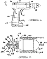
- FIG. 1 there is shown an exemplary, hand-held electric power tool 10 incorporating a motor 12 in accordance with the present invention.
- the motor 12 and its related circuitry may be used in a wide variety of electrically-driven power tools. Therefore, the illustration of a hand-held, electrically driven drill in Figure 1 will be understood as being for exemplary purposes only and not limiting the motor 12 and its related circuitry to any particular form of tool. It is anticipated that the motor 12 will find utility with electrically driven, hand-held grinders, circular saws, jigsaws, and virtually any other electrically-driven power tool in which the capability of operating off of an AC or DC power source would even further enhance the utility of the tool.
- the power tool 10 typically incorporates a user actuable trigger 14, a handle portion 16 and a chuck 18.
- the chuck is attached to a gear reduction assembly 20 which is in turn coupled to an output end of an armature shaft associated with the motor 12.
- a battery pack 24 is carried by the power tool 10 to supply DC power to the motor 12 for operation.
- a manually engageable AC/DC selector switch 26 allows a user to set the tool 10 for use with either AC or DC power. When the switch 26 is moved into its "AC" position, the motor 12 is able to receive AC power through a receptacle 28 to which an electrical extension cord may be releasably attached.
- the power tool 10 may be operated strictly off of the DC power available from the battery pack 24 when the switch 26 is in its "DC" position.
- the battery 24 pack comprises a removable, rechargeable 12 volt DC battery pack.
- selector switch 26 and the AC receptacle 28 may be located on the drill 10 at other locations.
- An option would be to have the switch 26 disposed within the recess 24a such that it is automatically engaged when the battery pack 24 is inserted, thereby automatically setting the tool 10 for operation from a DC power source. Removal of the DC battery back 24, and disengagement of the switch 26, would automatically set the tool 10 to operate off of AC power.
- the motor 12 incorporates a permanent magnet field 30.
- the permanent magnet field 30 is preferably provided in two sections 30a and 30b which each comprise a permanent ceramic magnet.
- Each permanent magnet 30a and 30b is adhered to a motor can 32, which is preferably a cold rolled steel motor can.
- Within the permanent magnet field 30 is an armature 34 which is supported on an armature shaft 36 extending coaxially through the armature.
- the armature shaft 36 includes a first end 36a and a second end 36b.
- a DC commutator 38 Disposed concentrically on the second end 36b is a DC commutator 38 which is fixedly secured to the second end 36b so as to rotate with the shaft 36.
- a phenolic insulating portion 38a insulates the commutator 38 from the armature shaft 36.
- Electrically coupled to the DC commutator 38 is a first (i.e., "DC") armature winding 40 which is wound in a conventional "on the fly” alpha winding pattern over a portion of the armature 34.
- the first armature winding 40 is preferably wound with heavy gauge wire, such as possibly 20AWG wire.
- AC commutator 42 Disposed fixedly to and coaxially over a portion of the DC commutator 38 is an AC commutator 42.
- the AC commutator 42 is electrically insulated from the DC commutator 38 via a phenolic insulating portion 42a and is electrically coupled to a second (i.e., "AC") armature winding 44.
- the second armature winding 44 is also wound over a portion of the first winding 40 in a conventional "on the fly" alpha winding pattern.
- the second armature winding 44 be wound on top of the first armature winding 40 due to the fact that the second winding 44 is of thinner gauge wire, for example 28 AWG wire, and would be susceptible to breakage if it is was wound first on the armature 34.
- a first pair of brushes 46 is associated with the DC commutator 38 and used to couple DC power from the battery 24 ( Figure 1) to the first armature winding 40 when the battery 24 is being used as the power source for the motor 12.
- a second pair of brushes 48 is coaxially disposed over the AC commutator 42 and used to transmit rectified AC power to the second armature winding 44 when an AC power source is being used to power the motor 12.
- both commutators 38 and 42 are disposed on the second end 36b of the armature shaft 36, that one of the commutators 38 or 42 could just as easily be disposed on the first end 36a of the armature shaft 36.
- Disposing both commutators 38 and 42 coaxially on one side of the armature 34 makes for a more compact motor assembly which is more desirable in hand held power tools where overall compactness of the tool is a desirable feature. Incorporating both commutators 38 and 42 on the same end of the armature shaft 36 also reduces the wiring complexity and the overall number of parts required for the motor 12.
- a 120 volt AC power source 52 is coupled across a full wave bridge rectifier circuit 52 comprised of diodes 52a-52d to provide a ripple DC signal.
- a filtering capacitor 53 provides a filtered DC signal to the brushes 48.
- the AC/DC selector switch comprises a rated single pole, double throw switch.
- the AC/DC switch 26 When the AC/DC switch 26 is in the "AC" position shown in Figure 3, and the trigger 14 is in the position shown in phantom in Figure 3, then the AC power source can be used to power the motor 12. In this mode current is supplied through the brushes 48 to the second armature winding 44.
- the switch 26 When the switch 26 is moved into the position shown in phantom in Figure 3 while the trigger 14 is held in the position shown in phantom, then the motor 12 may be powered from the battery pack 24.
- In this "DC" operating mode DC power is applied to the brushes 46.
- the brushes 46 transmit DC current through the DC commutator 38 to the first armature winding 40, thus enabling the motor 12 to be powered by the battery pack 24.
- a brake switch 54 is coupled across the AC brushes 48 to provide braking to the motor 12. It will be appreciated, however, that braking occurs in both the AC and DC operating modes.
- the second (i.e., AC) armature winding 44 has a higher electrical resistance than the first armature winding, which enables a "softer” braking action to be effected. If a "harder” (i.e., more abrupt) braking action is desired, the brake switch 54 may be coupled across the DC brushes 46. Thus, the braking action can be tailored for specific types of power tools. Brake switch 54 is a "normally closed” switch which closes automatically as soon as trigger switch 14 is released by a user into a "normally open” position.
- the housing of the power tool 10 in the preferred embodiment is nonetheless double insulated from the electrical system of the tool.
- a relatively low voltage DC power source i.e., a DC source less than 50 volts
- the housing of the power tool 10 in the preferred embodiment is nonetheless double insulated from the electrical system of the tool.
- power tools designed to be operated by a high voltage power source such as a conventional AC or corded power tool
- cordless or DC powered tools are powered by low voltage power sources and therefore do not require such safety measures. Consequently, conventional DC powered tools do not insulate the housing from the electrical system of the tool.
- AC/DC powered devices universally employ transformers to step down the high AC voltage and thereby isolate the device from the high voltage AC power source.
- the power tool 10 of the present invention may be double insulated in a variety of ways.
- One such way is through the use of a plastic gear on the input side of the gear reduction box 20 where the output of the box 20 is coupled to the chuck 18. This arrangement will serve to electrically isolate the electrically conductive portions of the tool 10 from the AC power source in the event of a short in the motor 12.
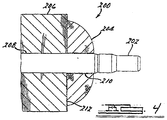
- FIGs 4-9 depict the effect of employing double insulation within a motor and housing. Double insulation techniques are well known in the art. Double insulated tools are typically constructed of two separate layers of electrical insulation or one double thickness of insulation between the operator and the tool's electrical system.
- a cross-sectional view of a standard, non-double insulated DC motor armature 200 is illustrated.
- the armature 200 consists of a shaft 202 with a core built up over it.
- the core is composed of many laminations 206 with notches along the outer periphery to hold the armature windings 204.
- a gear and/or chuck (not shown) is built onto the shaft at one end of the armature 200 to provide a means of transferring rotational energy to the working end of the power tool.
- a gear mechanism would convert rotational energy to the forward and back motion used to drive a reciprocating saw.
- the path from the armature shaft 202 to the gear mechanism or chuck, and finally to the working end is electrically conductive. Therefore any electrical energy that exists on the armature shaft 202 is conducted to the working end, which is exposed to the operator of the power tool 12.
- Locations 208, 210, and 212 indicate areas of the rotor that could become energized through contact with electrically live assemblies if insulation is not employed.
- the armature shaft 202 could be energized through contact with energized armature laminations 206.
- the armature shaft 202 could be energized through contact with end turns of the armature windings 204.
- the armature laminations 206 could be energized through contact to end turns of the armature windings 204.
- the armature 220 consists of a shaft 222 with a core built up over it.
- the core is composed of many laminations 226 with notches along the outer periphery to hold the armature windings 224.
- a chuck 228 is built onto the shaft at one end of the armature laminations 206 to provide a means of affixing a device such as a drill bit to the working end 208 (see Fig. 4) of the power tool.
- a molded plastic insulator 230 provides basic insulation between the armature windings 224 and the laminations 226 as well as between the shaft 222 and the windings 224.
- a press fit plastic tube insulator 232 encases the shaft 222 providing supplementary insulation to prevent the shaft from becoming energized if the basic insulation breaks down.
- a paper insulator 240 provides basic insulation between the armature windings 224 and the laminations 226.
- a second insulator 242 of double thickness, 2mm encases the shaft 222 providing reinforced insulation, which substitutes for supplementary insulation, to prevent the shaft from being energized through electrical shorts to the laminations 226 or the armature windings 224.
- FIG. 7 a third method of employing double insulation of the motor armature 220 of a power tool is illustrated.
- An insulator 250 of either paper or molded plastic provides basic insulation between the armature windings 224 and the laminations 226.
- An in situ molded thermoset plastic insulator 252 of double thickness encases the shaft 222 providing reinforced insulation, which substitutes for supplementary insulation, to prevent the shaft from being energized through electrical shorts to the laminations 226 or the armature windings 224.
- a slot liner insulator 260 provides basic insulation between the armature windings 224 and the laminations 226.
- the slot liner insulator is constructed of any suitable electrical insulator material such as paper, coated paper, polyester, and vulcanized fiber. Supplementary insulation is provided by a glass reinforced polyester insulator sleeve 262 which encase the shaft 222. The insulator sleeve prevents the shaft from becoming energized if the basic insulation provided by slot liner 260 fails.
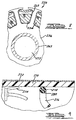
- a double insulated housing 270 of a power tool is illustrated.
- the double insulation methods employed are intended to prevent electrical energy within the housing 270 from energizing the outside surface of the housing 270.
- the housing 270 is depicted with a hypothetical metal foil covering 272 on the outside surface to simulate interaction with an operator.
- a ring terminal 274 and an insulated wire 276 that includes a conductive wire 278 and wire insulation 280. Electrical energy exists on both the ring terminal 274 and the conductive wire 278.
- Double insulation of the ring terminal 274 is provided by a double thickness, 2mm, of housing material which serves as a reinforced insulator.
- the wire insulation 280 provides basic insulation for conductive wire 278. Supplementary insulation is provided by the housing 270 which prevents electrical energy that breaks through the wire insulation from energizing the outside surface of the housing 270.
- the motor 12 of the present invention therefore represents a lightweight, compact means for powering a tool from either an AC or a DC power source.
- the motor 12 can be powered by a rechargeable DC battery pack or from a standard AC power source if a charged battery pack is not available or if the battery pack becomes discharged before the task at hand is completed.
- the motor 12 operates from either an AC or a DC power source with only a few additional component parts and without adding significantly to the overall weight, dimensions or cost of a power tool.
Landscapes
- Engineering & Computer Science (AREA)
- Power Engineering (AREA)
- Dc Machiner (AREA)
- Connection Of Motors, Electrical Generators, Mechanical Devices, And The Like (AREA)
- Control Of Direct Current Motors (AREA)
Abstract
Description
Claims (9)
- A hybrid AC/DC motor which can be operated from an alternating current power source or a direct current power source, the motor comprising:a permanent magnet field;an armature disposed within the permanent magnet field;a shaft extending concentrically through the armature and supporting the armature for rotation within the permanent magnet field;a DC commutator affixed to an end of the shaft;a first armature winding wound onto the armature and electrically coupled to the DC commutator;an AC commutator affixed to the shaft;a second armature winding wound onto the armature and electrically coupled to the AC commutator;a pair of DC brushes in contact with the DC commutator for coupling a DC current to the DC commutator when the power source comprises a DC battery; anda pair of AC brushes in contact with the AC commutator for coupling AC current to the AC commutator when the power source comprises an AC power source.
- A motor as claimed in claim 1, wherein the AC commutator is disposed coaxially over a portion of the DC commutator.
- A motor as claimed in claims 1 or 2, wherein the AC commutator and the DC commutator are both disposed at a common end of the armature shaft.
- A motor as claimed in any one of the claims 1, 2 or 3, wherein the AC armature winding is disposed over the DC armature winding.
- A hybrid AC/DC motor which can be operated from an alternating current power source or a direct current power source, the motor comprising:a permanent magnet field;an armature disposed within the permanent magnet field;a shaft extending concentrically through the armature and supporting the armature for rotation within the permanent magnet field;a DC commutator affixed to an end of the shaft;a first armature winding wound onto the armature and electrically coupled to the DC commutator;an AC commutator affixed to the end of the shaft concentrically over a portion of the DC commutator;a second armature winding wound onto the armature and electrically coupled to the AC commutator;a pair of DC brushes in contact with the DC commutator for coupling a DC current to the DC commutator when the power source comprises a DC battery; anda pair of AC brushes in contact with the AC commutator for coupling AC current to the AC commutator when the power source comprises an AC power source.
- A motor as claimed in claim 5, wherein the second armature winding is wound over the first armature winding.
- A motor as claimed in claims 5 or 6, wherein the permanent magnet field comprises a pair of ceramic magnet segments secured to a motor can.
- A power module for enabling AC or DC power to be used to power an electrically driven implement, the power module comprising:a rectifier circuit for receiving an AC input signal and generating a DC signal therefrom;a capacitor for filtering the DC signal;a battery;a motor including an AC commutator and an associated AC field winding, and a DC commutator having an associated DC field winding;a pair of AC brushes associated with the AC commutator;a pair of DC brushes associated with the DC commutator; anda switch for coupling either the battery or the AC power source to the motor.
- A power module as claimed in claim 8, further comprising:
a brake switch coupled across one pair of the brushes for braking the motor when an on/off power switch of the implement is engaged in an off position.
Applications Claiming Priority (2)
| Application Number | Priority Date | Filing Date | Title |
|---|---|---|---|
| US287812 | 1988-12-21 | ||
| US09/287,812 US6172437B1 (en) | 1999-04-07 | 1999-04-07 | Hybrid AC/DC motor |
Publications (3)
| Publication Number | Publication Date |
|---|---|
| EP1043829A2 true EP1043829A2 (en) | 2000-10-11 |
| EP1043829A3 EP1043829A3 (en) | 2002-04-17 |
| EP1043829B1 EP1043829B1 (en) | 2004-01-07 |
Family
ID=23104466
Family Applications (2)
| Application Number | Title | Priority Date | Filing Date |
|---|---|---|---|
| EP00920168A Withdrawn EP1214775A4 (en) | 1999-04-07 | 2000-04-06 | Hybrid ac/dc motor |
| EP00302948A Expired - Lifetime EP1043829B1 (en) | 1999-04-07 | 2000-04-07 | Hybrid AC/DC motor |
Family Applications Before (1)
| Application Number | Title | Priority Date | Filing Date |
|---|---|---|---|
| EP00920168A Withdrawn EP1214775A4 (en) | 1999-04-07 | 2000-04-06 | Hybrid ac/dc motor |
Country Status (9)
| Country | Link |
|---|---|
| US (1) | US6172437B1 (en) |
| EP (2) | EP1214775A4 (en) |
| JP (1) | JP2002541757A (en) |
| CN (1) | CN1153336C (en) |
| AT (1) | ATE257627T1 (en) |
| AU (1) | AU4074800A (en) |
| CA (1) | CA2364961C (en) |
| DE (1) | DE60007581T2 (en) |
| WO (1) | WO2000060723A1 (en) |
Cited By (3)
| Publication number | Priority date | Publication date | Assignee | Title |
|---|---|---|---|---|
| WO2010107982A1 (en) * | 2009-03-20 | 2010-09-23 | Wagner Spray Tech Corporation | Dual voltage electromagnet motor for airless fluid sprayer |
| EP2754536A3 (en) * | 2013-01-08 | 2015-09-16 | Techtronic Outdoor Products Technology Limited | Motor system for dual voltage devices |
| EP3241272B1 (en) * | 2014-12-31 | 2023-05-03 | Techtronic Industries Co., Ltd. | Method and system for braking a motor |
Families Citing this family (29)
| Publication number | Priority date | Publication date | Assignee | Title |
|---|---|---|---|---|
| US6683396B2 (en) * | 1999-07-02 | 2004-01-27 | Matsushita Electric Works, Ltd. | Portable motor powered device |
| JP3758496B2 (en) * | 2000-11-06 | 2006-03-22 | 株式会社日立製作所 | Joint drive device |
| US6753637B2 (en) * | 2001-09-07 | 2004-06-22 | Honeywell International, Inc. | Exciter rotor assembly |
| US20030132725A1 (en) * | 2002-01-16 | 2003-07-17 | Defond Manufacturing Limited | Controller for motor driven device |
| US20050273969A1 (en) * | 2002-11-12 | 2005-12-15 | Watson James B | AC/DC portable wet/dry vacuum having improved portability and convenience |
| US7653963B2 (en) | 2002-11-12 | 2010-02-02 | Black & Decker Inc. | AC/DC hand portable wet/dry vacuum having improved portability and convenience |
| EP1495706B1 (en) * | 2003-07-10 | 2013-05-01 | Black & Decker Inc. | Vacuum cleaner |
| FR2867322B1 (en) * | 2004-03-03 | 2006-04-21 | Seb Sa | HOUSEHOLD APPLIANCE INCLUDING AN ELECTRIC MOTOR |
| US20090026874A1 (en) * | 2005-04-30 | 2009-01-29 | Michael Schmohl | Method for Mounting an Armature Laminated Core on an Armature Shaft and Armature Laminated Core for an Armature Shaft and Armature Shaft with Pressed-On Armature Laminated Core |
| CA2545036A1 (en) * | 2006-03-01 | 2007-09-01 | Mattel, Inc. | Child support with multiple electrical modes |
| US20090228149A1 (en) * | 2006-08-17 | 2009-09-10 | Glacier Bay, Inc. | Environmental control and power system |
| US7479754B2 (en) | 2006-10-17 | 2009-01-20 | Desa Ip Llc | Hybrid electric lawnmower |
| WO2008048618A2 (en) * | 2006-10-17 | 2008-04-24 | Desa Ip. Llc | Hybrid electric device |
| US7728534B2 (en) * | 2006-10-17 | 2010-06-01 | Mtd Products Inc | Hybrid electric lawnmower |
| US20080120955A1 (en) * | 2006-10-17 | 2008-05-29 | Lucas Delbert R | Hybrid electric lawnmower |
| US8732896B2 (en) | 2006-10-17 | 2014-05-27 | Mtd Products Inc | Hybrid electric cleaning device |
| US8076873B1 (en) | 2007-06-01 | 2011-12-13 | Mtd Products Inc | Hybrid outdoor power equipment |
| EP2110921B1 (en) | 2008-04-14 | 2013-06-19 | Stanley Black & Decker, Inc. | Battery management system for a cordless tool |
| DE102008019546A1 (en) * | 2008-04-18 | 2009-10-22 | Continental Teves Ag & Co. Ohg | Motor pump unit for motor vehicle brake control systems |
| JP2012533273A (en) * | 2009-07-09 | 2012-12-20 | パク,ジェ−スン | AC generator and DC generator using field pole generator and rotating DC supply brush |
| US9099910B2 (en) | 2011-10-18 | 2015-08-04 | The Chamberlain Group, Inc. | Multi-mode motor for switching among motor power supplies |
| CN104079133A (en) * | 2013-03-25 | 2014-10-01 | 德昌电机(深圳)有限公司 | Direct current motor |
| US9670034B2 (en) | 2014-04-29 | 2017-06-06 | The Chamberlain Group, Inc. | Power air compressor |
| EP3273569B1 (en) | 2014-05-18 | 2018-08-15 | Black & Decker, Inc. | Power tool system |
| US9893384B2 (en) | 2014-05-18 | 2018-02-13 | Black & Decker Inc. | Transport system for convertible battery pack |
| CN105471146A (en) * | 2014-09-04 | 2016-04-06 | 苏州宝时得电动工具有限公司 | Electric tool |
| KR101748829B1 (en) | 2015-12-07 | 2017-07-03 | (주)대영전장시스템 | Convergence-type dc motor |
| WO2018119256A1 (en) | 2016-12-23 | 2018-06-28 | Black & Decker Inc. | Cordless power tool system |
| CN107596590A (en) * | 2017-10-25 | 2018-01-19 | 奥来救援科技有限公司 | AC/DC electric hydaulic expander |
Family Cites Families (20)
| Publication number | Priority date | Publication date | Assignee | Title |
|---|---|---|---|---|
| GB248516A (en) * | 1924-12-29 | 1926-03-11 | John William Tyler | An improved electric generator |
| US2339228A (en) | 1938-05-31 | 1944-01-11 | Edward E Stout | Dynamoelectric machine |
| US3079510A (en) * | 1957-11-01 | 1963-02-26 | Licentia Gmbh | Dry shaving apparatus combining varying sources of power |
| US3160772A (en) | 1960-02-02 | 1964-12-08 | Wincharger Corp | Plural voltage electric generator |
| US3525912A (en) * | 1966-03-28 | 1970-08-25 | Scovill Manufacturing Co | Selectable power source for a motor driven appliance |
| US3652879A (en) * | 1970-07-22 | 1972-03-28 | Thor Power Tool Co | Electric power tool |
| US3791684A (en) * | 1972-08-24 | 1974-02-12 | Eaton Stamping Co | Electric starter motor |
| US4080540A (en) * | 1973-10-08 | 1978-03-21 | Canon Kabushiki Kaisha | Low-powdered stepping motor |
| JPS5742565U (en) | 1980-08-19 | 1982-03-08 | ||
| FR2513453A1 (en) * | 1981-09-23 | 1983-03-25 | Portescap | MACHINE AND ELECTRIC DRIVE DEVICE |
| US4462467A (en) * | 1981-11-09 | 1984-07-31 | Hilti Aktiengesellschaft | Percussion drill machine |
| US4507720A (en) * | 1982-07-26 | 1985-03-26 | Safe-T-Plug, Inc. | Automotive/home power interconnection system |
| DE3233015C1 (en) * | 1982-09-06 | 1984-03-15 | Henschel Gerätebau GmbH, 3035 Hodenhagen | Electric motor for optional connection to direct or alternating current |
| US4910790A (en) | 1987-01-13 | 1990-03-20 | Magna International (Canada) Inc. | Two-speed motor |
| US4835410A (en) * | 1988-02-26 | 1989-05-30 | Black & Decker Inc. | Dual-mode corded/cordless system for power-operated devices |
| US4990844A (en) | 1989-10-18 | 1991-02-05 | Eaton Corporation | DC braking of inverter-driven AC motors |
| US5294874A (en) | 1992-08-13 | 1994-03-15 | Milwaukee Electric Tool Corporation | Dynamic brake circuit for an electric motor |
| DE4324256A1 (en) * | 1993-07-20 | 1995-01-26 | Braun Ag | Commutator motor |
| FI97718C (en) * | 1995-03-24 | 1997-02-10 | Kone Oy | Elevator motor emergency drive |
| US5648706A (en) | 1995-09-28 | 1997-07-15 | S-B Power Tool Company | Electric brake for commutated motor |
-
1999
- 1999-04-07 US US09/287,812 patent/US6172437B1/en not_active Expired - Lifetime
-
2000
- 2000-04-06 CN CNB008080402A patent/CN1153336C/en not_active Expired - Fee Related
- 2000-04-06 EP EP00920168A patent/EP1214775A4/en not_active Withdrawn
- 2000-04-06 WO PCT/US2000/009088 patent/WO2000060723A1/en not_active Ceased
- 2000-04-06 AU AU40748/00A patent/AU4074800A/en not_active Abandoned
- 2000-04-06 CA CA002364961A patent/CA2364961C/en not_active Expired - Fee Related
- 2000-04-06 JP JP2000610112A patent/JP2002541757A/en active Pending
- 2000-04-07 AT AT00302948T patent/ATE257627T1/en not_active IP Right Cessation
- 2000-04-07 DE DE60007581T patent/DE60007581T2/en not_active Expired - Lifetime
- 2000-04-07 EP EP00302948A patent/EP1043829B1/en not_active Expired - Lifetime
Cited By (6)
| Publication number | Priority date | Publication date | Assignee | Title |
|---|---|---|---|---|
| WO2010107982A1 (en) * | 2009-03-20 | 2010-09-23 | Wagner Spray Tech Corporation | Dual voltage electromagnet motor for airless fluid sprayer |
| US8573511B2 (en) | 2009-03-20 | 2013-11-05 | Wagner Spray Tech Corporation | Dual voltage electromagnet motor for airless fluid sprayer |
| EP2754536A3 (en) * | 2013-01-08 | 2015-09-16 | Techtronic Outdoor Products Technology Limited | Motor system for dual voltage devices |
| AU2013267076B2 (en) * | 2013-01-08 | 2018-02-01 | Techtronic Outdoor Products Technology Limited | Motor system for dual voltage devices |
| AU2017279698B2 (en) * | 2013-01-08 | 2019-05-02 | Techtronic Outdoor Products Technology Limited | Motor system for dual voltage devices |
| EP3241272B1 (en) * | 2014-12-31 | 2023-05-03 | Techtronic Industries Co., Ltd. | Method and system for braking a motor |
Also Published As
| Publication number | Publication date |
|---|---|
| JP2002541757A (en) | 2002-12-03 |
| EP1214775A1 (en) | 2002-06-19 |
| CA2364961C (en) | 2008-06-17 |
| WO2000060723A1 (en) | 2000-10-12 |
| EP1043829B1 (en) | 2004-01-07 |
| EP1043829A3 (en) | 2002-04-17 |
| EP1214775A4 (en) | 2004-08-11 |
| DE60007581D1 (en) | 2004-02-12 |
| AU4074800A (en) | 2000-10-23 |
| DE60007581T2 (en) | 2004-12-23 |
| US6172437B1 (en) | 2001-01-09 |
| ATE257627T1 (en) | 2004-01-15 |
| CA2364961A1 (en) | 2000-10-12 |
| CN1353881A (en) | 2002-06-12 |
| CN1153336C (en) | 2004-06-09 |
Similar Documents
| Publication | Publication Date | Title |
|---|---|---|
| EP1043829B1 (en) | Hybrid AC/DC motor | |
| AU2017279698B2 (en) | Motor system for dual voltage devices | |
| US6296065B1 (en) | Dual-mode non-isolated corded system for transportable cordless power tools | |
| US20030127932A1 (en) | Portable motor powered device | |
| CN104853879B (en) | The hand held power machine of motor and the electronic device integrated with electronic commutation | |
| US3525912A (en) | Selectable power source for a motor driven appliance | |
| US5294874A (en) | Dynamic brake circuit for an electric motor | |
| US6286609B1 (en) | AC/DC chopper for power tool | |
| CN101663139A (en) | Cutting knives especially for cutting food | |
| US20240258883A1 (en) | High-powered power tool system | |
| WO2016034133A1 (en) | Power tool | |
| EP1193843B1 (en) | Commutator motor | |
| EP1110678B1 (en) | Portable motor power device | |
| US7911090B2 (en) | Stator of an electrical machine, electrical machine, and power tool | |
| US8084900B2 (en) | Asymmetrical stator of an electrical machine | |
| CN215817842U (en) | Electric tool | |
| JP3870645B2 (en) | Electric tool | |
| CN121312044A (en) | Integrated motor braking resistor | |
| CN120712708A (en) | Stator with protective device |
Legal Events
| Date | Code | Title | Description |
|---|---|---|---|
| PUAI | Public reference made under article 153(3) epc to a published international application that has entered the european phase |
Free format text: ORIGINAL CODE: 0009012 |
|
| AK | Designated contracting states |
Kind code of ref document: A2 Designated state(s): AT BE CH CY DE DK ES FI FR GB GR IE IT LI LU MC NL PT SE |
|
| AX | Request for extension of the european patent |
Free format text: AL;LT;LV;MK;RO;SI |
|
| PUAL | Search report despatched |
Free format text: ORIGINAL CODE: 0009013 |
|
| AK | Designated contracting states |
Kind code of ref document: A3 Designated state(s): AT BE CH CY DE DK ES FI FR GB GR IE IT LI LU MC NL PT SE |
|
| AX | Request for extension of the european patent |
Free format text: AL;LT;LV;MK;RO;SI |
|
| RIC1 | Information provided on ipc code assigned before grant |
Free format text: 7H 02K 23/36 A |
|
| 17P | Request for examination filed |
Effective date: 20021017 |
|
| AKX | Designation fees paid |
Free format text: AT BE CH CY DE DK ES FI FR GB GR IE IT LI LU MC NL PT SE |
|
| 17Q | First examination report despatched |
Effective date: 20030115 |
|
| GRAP | Despatch of communication of intention to grant a patent |
Free format text: ORIGINAL CODE: EPIDOSNIGR1 |
|
| GRAS | Grant fee paid |
Free format text: ORIGINAL CODE: EPIDOSNIGR3 |
|
| GRAA | (expected) grant |
Free format text: ORIGINAL CODE: 0009210 |
|
| AK | Designated contracting states |
Kind code of ref document: B1 Designated state(s): AT BE CH CY DE DK ES FI FR GB GR IE IT LI LU MC NL PT SE |
|
| PG25 | Lapsed in a contracting state [announced via postgrant information from national office to epo] |
Ref country code: CY Free format text: LAPSE BECAUSE OF FAILURE TO SUBMIT A TRANSLATION OF THE DESCRIPTION OR TO PAY THE FEE WITHIN THE PRESCRIBED TIME-LIMIT Effective date: 20040107 Ref country code: FR Free format text: LAPSE BECAUSE OF FAILURE TO SUBMIT A TRANSLATION OF THE DESCRIPTION OR TO PAY THE FEE WITHIN THE PRESCRIBED TIME-LIMIT Effective date: 20040107 Ref country code: NL Free format text: LAPSE BECAUSE OF FAILURE TO SUBMIT A TRANSLATION OF THE DESCRIPTION OR TO PAY THE FEE WITHIN THE PRESCRIBED TIME-LIMIT Effective date: 20040107 Ref country code: AT Free format text: LAPSE BECAUSE OF FAILURE TO SUBMIT A TRANSLATION OF THE DESCRIPTION OR TO PAY THE FEE WITHIN THE PRESCRIBED TIME-LIMIT Effective date: 20040107 Ref country code: FI Free format text: LAPSE BECAUSE OF FAILURE TO SUBMIT A TRANSLATION OF THE DESCRIPTION OR TO PAY THE FEE WITHIN THE PRESCRIBED TIME-LIMIT Effective date: 20040107 Ref country code: BE Free format text: LAPSE BECAUSE OF FAILURE TO SUBMIT A TRANSLATION OF THE DESCRIPTION OR TO PAY THE FEE WITHIN THE PRESCRIBED TIME-LIMIT Effective date: 20040107 Ref country code: LI Free format text: LAPSE BECAUSE OF FAILURE TO SUBMIT A TRANSLATION OF THE DESCRIPTION OR TO PAY THE FEE WITHIN THE PRESCRIBED TIME-LIMIT Effective date: 20040107 Ref country code: CH Free format text: LAPSE BECAUSE OF FAILURE TO SUBMIT A TRANSLATION OF THE DESCRIPTION OR TO PAY THE FEE WITHIN THE PRESCRIBED TIME-LIMIT Effective date: 20040107 Ref country code: IT Free format text: LAPSE BECAUSE OF FAILURE TO SUBMIT A TRANSLATION OF THE DESCRIPTION OR TO PAY THE FEE WITHIN THE PRESCRIBED TIME-LIMIT;WARNING: LAPSES OF ITALIAN PATENTS WITH EFFECTIVE DATE BEFORE 2007 MAY HAVE OCCURRED AT ANY TIME BEFORE 2007. THE CORRECT EFFECTIVE DATE MAY BE DIFFERENT FROM THE ONE RECORDED. Effective date: 20040107 |
|
| REG | Reference to a national code |
Ref country code: GB Ref legal event code: FG4D |
|
| REG | Reference to a national code |
Ref country code: CH Ref legal event code: EP |
|
| REG | Reference to a national code |
Ref country code: IE Ref legal event code: FG4D |
|
| REF | Corresponds to: |
Ref document number: 60007581 Country of ref document: DE Date of ref document: 20040212 Kind code of ref document: P |
|
| PG25 | Lapsed in a contracting state [announced via postgrant information from national office to epo] |
Ref country code: DK Free format text: LAPSE BECAUSE OF FAILURE TO SUBMIT A TRANSLATION OF THE DESCRIPTION OR TO PAY THE FEE WITHIN THE PRESCRIBED TIME-LIMIT Effective date: 20040407 Ref country code: LU Free format text: LAPSE BECAUSE OF NON-PAYMENT OF DUE FEES Effective date: 20040407 Ref country code: GR Free format text: LAPSE BECAUSE OF FAILURE TO SUBMIT A TRANSLATION OF THE DESCRIPTION OR TO PAY THE FEE WITHIN THE PRESCRIBED TIME-LIMIT Effective date: 20040407 Ref country code: IE Free format text: LAPSE BECAUSE OF NON-PAYMENT OF DUE FEES Effective date: 20040407 Ref country code: SE Free format text: LAPSE BECAUSE OF FAILURE TO SUBMIT A TRANSLATION OF THE DESCRIPTION OR TO PAY THE FEE WITHIN THE PRESCRIBED TIME-LIMIT Effective date: 20040407 |
|
| PG25 | Lapsed in a contracting state [announced via postgrant information from national office to epo] |
Ref country code: ES Free format text: LAPSE BECAUSE OF FAILURE TO SUBMIT A TRANSLATION OF THE DESCRIPTION OR TO PAY THE FEE WITHIN THE PRESCRIBED TIME-LIMIT Effective date: 20040418 |
|
| PG25 | Lapsed in a contracting state [announced via postgrant information from national office to epo] |
Ref country code: MC Free format text: LAPSE BECAUSE OF NON-PAYMENT OF DUE FEES Effective date: 20040430 |
|
| NLV1 | Nl: lapsed or annulled due to failure to fulfill the requirements of art. 29p and 29m of the patents act | ||
| REG | Reference to a national code |
Ref country code: CH Ref legal event code: PL |
|
| PLBE | No opposition filed within time limit |
Free format text: ORIGINAL CODE: 0009261 |
|
| STAA | Information on the status of an ep patent application or granted ep patent |
Free format text: STATUS: NO OPPOSITION FILED WITHIN TIME LIMIT |
|
| 26N | No opposition filed |
Effective date: 20041008 |
|
| EN | Fr: translation not filed | ||
| REG | Reference to a national code |
Ref country code: IE Ref legal event code: MM4A |
|
| PG25 | Lapsed in a contracting state [announced via postgrant information from national office to epo] |
Ref country code: PT Free format text: LAPSE BECAUSE OF NON-PAYMENT OF DUE FEES Effective date: 20040607 |
|
| PGFP | Annual fee paid to national office [announced via postgrant information from national office to epo] |
Ref country code: GB Payment date: 20130429 Year of fee payment: 14 Ref country code: DE Payment date: 20130429 Year of fee payment: 14 |
|
| REG | Reference to a national code |
Ref country code: DE Ref legal event code: R119 Ref document number: 60007581 Country of ref document: DE |
|
| GBPC | Gb: european patent ceased through non-payment of renewal fee |
Effective date: 20140407 |
|
| REG | Reference to a national code |
Ref country code: DE Ref legal event code: R119 Ref document number: 60007581 Country of ref document: DE Effective date: 20141101 |
|
| PG25 | Lapsed in a contracting state [announced via postgrant information from national office to epo] |
Ref country code: DE Free format text: LAPSE BECAUSE OF NON-PAYMENT OF DUE FEES Effective date: 20141101 Ref country code: GB Free format text: LAPSE BECAUSE OF NON-PAYMENT OF DUE FEES Effective date: 20140407 |