EP1043812A1 - Electrical plug connection, particularly for motor vehicle applications - Google Patents
Electrical plug connection, particularly for motor vehicle applications Download PDFInfo
- Publication number
- EP1043812A1 EP1043812A1 EP00107032A EP00107032A EP1043812A1 EP 1043812 A1 EP1043812 A1 EP 1043812A1 EP 00107032 A EP00107032 A EP 00107032A EP 00107032 A EP00107032 A EP 00107032A EP 1043812 A1 EP1043812 A1 EP 1043812A1
- Authority
- EP
- European Patent Office
- Prior art keywords
- slide
- plug connection
- carriage
- plug
- catch
- Prior art date
- Legal status (The legal status is an assumption and is not a legal conclusion. Google has not performed a legal analysis and makes no representation as to the accuracy of the status listed.)
- Granted
Links
- 230000000295 complement effect Effects 0.000 claims abstract description 4
- 210000002105 tongue Anatomy 0.000 description 8
- 238000005192 partition Methods 0.000 description 7
- 230000037431 insertion Effects 0.000 description 6
- 238000003780 insertion Methods 0.000 description 6
- 230000005540 biological transmission Effects 0.000 description 3
- 230000000694 effects Effects 0.000 description 3
- 239000004020 conductor Substances 0.000 description 1
- 230000008878 coupling Effects 0.000 description 1
- 238000010168 coupling process Methods 0.000 description 1
- 238000005859 coupling reaction Methods 0.000 description 1
- 230000005489 elastic deformation Effects 0.000 description 1
- 238000007789 sealing Methods 0.000 description 1
Images


Classifications
-
- H—ELECTRICITY
- H01—ELECTRIC ELEMENTS
- H01R—ELECTRICALLY-CONDUCTIVE CONNECTIONS; STRUCTURAL ASSOCIATIONS OF A PLURALITY OF MUTUALLY-INSULATED ELECTRICAL CONNECTING ELEMENTS; COUPLING DEVICES; CURRENT COLLECTORS
- H01R13/00—Details of coupling devices of the kinds covered by groups H01R12/70 or H01R24/00 - H01R33/00
- H01R13/64—Means for preventing incorrect coupling
- H01R13/641—Means for preventing incorrect coupling by indicating incorrect coupling; by indicating correct or full engagement
-
- H—ELECTRICITY
- H01—ELECTRIC ELEMENTS
- H01R—ELECTRICALLY-CONDUCTIVE CONNECTIONS; STRUCTURAL ASSOCIATIONS OF A PLURALITY OF MUTUALLY-INSULATED ELECTRICAL CONNECTING ELEMENTS; COUPLING DEVICES; CURRENT COLLECTORS
- H01R13/00—Details of coupling devices of the kinds covered by groups H01R12/70 or H01R24/00 - H01R33/00
- H01R13/646—Details of coupling devices of the kinds covered by groups H01R12/70 or H01R24/00 - H01R33/00 specially adapted for high-frequency, e.g. structures providing an impedance match or phase match
- H01R13/6461—Means for preventing cross-talk
-
- H—ELECTRICITY
- H01—ELECTRIC ELEMENTS
- H01R—ELECTRICALLY-CONDUCTIVE CONNECTIONS; STRUCTURAL ASSOCIATIONS OF A PLURALITY OF MUTUALLY-INSULATED ELECTRICAL CONNECTING ELEMENTS; COUPLING DEVICES; CURRENT COLLECTORS
- H01R24/00—Two-part coupling devices, or either of their cooperating parts, characterised by their overall structure
-
- H—ELECTRICITY
- H01—ELECTRIC ELEMENTS
- H01R—ELECTRICALLY-CONDUCTIVE CONNECTIONS; STRUCTURAL ASSOCIATIONS OF A PLURALITY OF MUTUALLY-INSULATED ELECTRICAL CONNECTING ELEMENTS; COUPLING DEVICES; CURRENT COLLECTORS
- H01R13/00—Details of coupling devices of the kinds covered by groups H01R12/70 or H01R24/00 - H01R33/00
- H01R13/62—Means for facilitating engagement or disengagement of coupling parts or for holding them in engagement
- H01R13/639—Additional means for holding or locking coupling parts together, after engagement, e.g. separate keylock, retainer strap
-
- H—ELECTRICITY
- H01—ELECTRIC ELEMENTS
- H01R—ELECTRICALLY-CONDUCTIVE CONNECTIONS; STRUCTURAL ASSOCIATIONS OF A PLURALITY OF MUTUALLY-INSULATED ELECTRICAL CONNECTING ELEMENTS; COUPLING DEVICES; CURRENT COLLECTORS
- H01R2107/00—Four or more poles
-
- H—ELECTRICITY
- H01—ELECTRIC ELEMENTS
- H01R—ELECTRICALLY-CONDUCTIVE CONNECTIONS; STRUCTURAL ASSOCIATIONS OF A PLURALITY OF MUTUALLY-INSULATED ELECTRICAL CONNECTING ELEMENTS; COUPLING DEVICES; CURRENT COLLECTORS
- H01R2201/00—Connectors or connections adapted for particular applications
- H01R2201/26—Connectors or connections adapted for particular applications for vehicles
Definitions
- the invention relates to an electrical plug connection, particularly for motor vehicle applications, with a plug housing, a contact housing complementary to the plug housing and a transverse slide for locking the plug housing in the contact housing.
- Plug connections of this kind are mainly used in a wall of a housing in order to connect to external conductors electrical connections of a device in the housing.
- plug connections of this kind are used for pre-cabling for motor vehicle transmissions. It is particularly in the area of motor vehicle transmissions that intense vibrations occur in addition to relatively high operating temperatures and may result in the plug connections loosening or breaking away.
- plug connections have locking devices which are intended to ensure that the plug housing is secured in the contact housing.
- care must be taken to ensure that the locking device really is engaged.
- the fitter brings the locking device only into an intermediate position in which although the plug housing has been pushed into the contact housing the locking device is not in its catch position. In that case the plug connection may automatically break away due to the high vibrations occurring in the operation of the motor vehicle.
- the object of the invention is to provide an electrical plug connection wherein assembly faults caused by incomplete closure or engagement of the locking device are reliably avoided.
- the plug connection comprises a plug housing, a contact housing complementary to the plug housing and a transverse slide for locking the plug housing in the contact housing.
- At least one spring element acts on at least one movable carriage, said spring element exerting an increasing stress on the slide during the closing of the latter and pushing it back into its open position in the event of an incomplete closing operation.
- the slide is locked in its closed position only on complete closure.
- the co-operation of the slide, spring element and carriage according to the invention has the effect that the electrical plug connection and its locking device are always in a defined state and this state is unmistakably indicated to the fitter. If the slide is inserted only incompletely, coupling of the carriage to the slide by way of the spring element causes the latter to exert a force on the slide which, after the manual insertion force has ceased, automatically pushes it back into its open position. This indicates to the fitter that the locking device has not been engaged and hence cannot fulfil its securing function.
- Another special feature of the invention is that on the insertion of the slide the two main parts of the plug connection, namely the plug housing fixed on a housing wall, and the contact housing, are clamped together, this being achieved by the configuration of guides in the slide to receive studs on the plug housing.
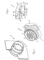
- the electrical plug connection shown in Fig. 1 is designed as a pre-cabling for the transmission of motor vehicles and consists of a plug part I fixed in a wall opening of a vehicle part and a contact part II which can be plugged therein and which is constructed according to the invention and will be described in detail hereinafter.
- the contact part II comprises a contact housing 1 with an annular front part 2 in which there is incorporated a disc-shaped contact insert 3 and a profiled sealing ring 4 is snapped on the outside thereof.
- a locking device for securing the contact housing 1 in the plug housing of the plug part I is constructed as a slide 5 in the form of a yoke with two limbs 6, 7.
- a C-shaped yoke 9 is formed on the substantially square back part 8 of the slide 5, and its arms 10, 11 extend over and parallel to the two limbs 6, 7 and each has at its flat inside a guide groove 12, the arms 10, 11 being guided transversely of the plug axis in two parallel guides 42, 43 formed on the contact housing 1.
- each limb 6, 7 has two side walls 21, 22 which extend in parallel in the sliding direction and which together with a partition 23 formed on one side each define an elongate recess 13, 14.
- An axial stud 15, 16 is formed on the inner end wall 24 of each recess 13, 14 and apertures 17, 18 are provided on both sides in the two side walls 21, 22 into each of which there projects on one side a tongue 19, 20 with an oblique ramp surface.
- Each limb 6, 7 of the slide 5 has an associated carriage 25 shown in Figs. 4a and 4b.
- Each carriage 25 has a substantially rectangular elongate baseplate 26, at one end of which there is integrally formed a support plate 27 perpendicular thereto with a pin 28 extending parallel to the baseplate 26.
- Parallel to both sides of the baseplate 26 there extend webs 30, 31 in the form of tongues which at the ends are integrally connected to the widened end part 29 of the baseplate 26.
- Formed in each web 30, 31 is a downwardly open cut-out 32, 33, which is defined at one end by an oblique surface 34, 35 and at the other end by a vertical surface 36, 37.
- the undersides of the baseplate 26 and of the webs 30, 31 lie in one plane.
- Fig. 5 shows one limb 6 of the slide 5 of Fig. 3 together with a built-in carriage 25 according to Fig. 4a, 4b without an expanding spring.
- the carriage 25 is an end position in which its support plate 27 bears against the end partition 23 of the limb 6.
- the width of the carriage 25 corresponds to the width of the limb 6 so that the two tongue-shaped elastically deformable webs 30, 31 are situated opposite the tongues 19, 20 projecting into the apertures 17, 18.
- the top of the support plate 27 is in line with the upper surfaces of the walls 21 to 24 of the limb 6.
- the height of the webs 30, 31 of the carriage 25 is smaller than the height of the support plate 27, so that the front zone 21a, 22a of the side walls 21, 22 can slide on the upper side of the webs 30, 31.
- the width of the side walls 21, 22 corresponds to the width of the webs 30, 31.
- the middle zone 21b, 22b of the side walls 21, 22 has the already mentioned apertures 17, 18 to receive the webs 30, 31 so that the height of the middle zone 21b, 22b turns out smaller than the height of the front zone 21a, 22a.
- This middle zone 21b, 22b is continued by the rear zone 21c, 22c of the side walls 21, 22 so that the undersides of the webs 30, 31, of the tongues 19, 20 and of the rear zone 21c, 22c of the side walls 21, 22 are in one plane.
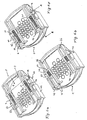
- Figs. 6a to 6c show the back of the contact housing 1 with a slide 5 in different positions, two built-in carriages 25 and two expanding springs 40, 41 each disposed in a recess 13, 14 in the limbs 6, 7 and clamped between the pin 28 and the axial studs 15, 16.
- Figs. 7a to 7d which illustrate a section on the line A-A included by way of example in Fig. 6c, the upper side of the side walls 21, 22 of the limbs 6, 7 are guided by guide rails 44, 45 formed integrally on the contact housing 1.
- the height of the end wall 24 turns out smaller than the height of the rear zone 21c of the side wall 21, so that on actuation of the slide 5 the baseplate 26 can slide under this end wall 24.
- a matching catch 48 is also formed on the back of the contact housing 1 for each cut-out 32, 33 of the carriage 25 which at one end is defined by an oblique surface 49 and at the other end by a vertical surface 50.
- Fig. 6a shows the slide 5 in the open position as the fitter receives the contact housing I before insertion
- Fig. 7a shows the corresponding sectional drawing to Fig. 6a.
- the support plate 27 abuts the partition 23.
- the catch 48 of the contact housing 1 is situated in the cut-out 33 of the web 31.
- the underside of the web 31 rests on the back of the contact housing 1.
- the distance between the support plate 27 and the end plate 24 is at the maximum in this state of the slide so that the expanding spring 41 situated therebetween is relieved of stress.
- the matching plug part I (see Fig. 1) is now plugged on to the front of the contact part II.
- the fitter must press the slide 5 in the direction of arrow G.
- the upper side of the side walls 21, 22 is guided by the guide rails 44, 45.
- the underside of the front zone 21a of the side wall 21 slides on the upper side of the web 31.
- the entire carriage 25 does not change its position, since the catch 48 holds the web 31 fast.
- the end wall 24 slides over the baseplate 26. The distance between the support plate 27 and end plate 24 is reduced, i.e. the expansion spring 41 is stressed.
- the tongue 19 projects into the aperture.
- the catch elements (not shown) engage, the oblique ramp surface of the tongue 19 passes beneath the web 31 (see Fig. 7b).
- the ramp 38 of the web 31 facilitates the insertion of the tongue 19 thereunder.
- the web 31 is lifted over the catch 48 into the aperture 17 and is slightly elastically deformed. Since the slide 5 is connected to the contact housing 1 because of the catch elements (not shown), the expanding spring 41 can only be relieved of stress by the carriage 25 moving together with the webs 30, 31 in the direction of the partition 23. After overcoming the catch 48 the web 31 again comes on to the back of the contact housing 1 because of its elastic deformation (see Fig. 7c).
- the force directed towards the back of the contact housing 1 is generated by rigid webs 30, 31 and a flexible baseplate 26.
- the support plate 27 would also be lifted and the webs 30, 31 would not undergo deformation. Instead the baseplate 26 would be elastically deformed.
- Fig. 7c shows an intermediate position of Fig. 7b, which is the sectional view of Fig. 6b, and of 7d, which is the sectional view of Fig. 6c. None of the Figures 6a to 6c shows the position of Fig. 7c.
Landscapes
- Details Of Connecting Devices For Male And Female Coupling (AREA)
- Connector Housings Or Holding Contact Members (AREA)
- Motor Or Generator Frames (AREA)
Abstract

Description
- The invention relates to an electrical plug connection, particularly for motor vehicle applications, with a plug housing, a contact housing complementary to the plug housing and a transverse slide for locking the plug housing in the contact housing.
- Plug connections of this kind are mainly used in a wall of a housing in order to connect to external conductors electrical connections of a device in the housing. For example, plug connections of this kind are used for pre-cabling for motor vehicle transmissions. It is particularly in the area of motor vehicle transmissions that intense vibrations occur in addition to relatively high operating temperatures and may result in the plug connections loosening or breaking away.
- To secure the connection, known plug connections have locking devices which are intended to ensure that the plug housing is secured in the contact housing. On assembly, of course, care must be taken to ensure that the locking device really is engaged. In practice it may happen that the fitter brings the locking device only into an intermediate position in which although the plug housing has been pushed into the contact housing the locking device is not in its catch position. In that case the plug connection may automatically break away due to the high vibrations occurring in the operation of the motor vehicle.
- The object of the invention is to provide an electrical plug connection wherein assembly faults caused by incomplete closure or engagement of the locking device are reliably avoided.
- This problem is solved by the features of
claim 1. - The plug connection according to the invention comprises a plug housing, a contact housing complementary to the plug housing and a transverse slide for locking the plug housing in the contact housing. At least one spring element acts on at least one movable carriage, said spring element exerting an increasing stress on the slide during the closing of the latter and pushing it back into its open position in the event of an incomplete closing operation. The slide is locked in its closed position only on complete closure.
- The co-operation of the slide, spring element and carriage according to the invention has the effect that the electrical plug connection and its locking device are always in a defined state and this state is unmistakably indicated to the fitter. If the slide is inserted only incompletely, coupling of the carriage to the slide by way of the spring element causes the latter to exert a force on the slide which, after the manual insertion force has ceased, automatically pushes it back into its open position. This indicates to the fitter that the locking device has not been engaged and hence cannot fulfil its securing function.
- Another special feature of the invention is that on the insertion of the slide the two main parts of the plug connection, namely the plug housing fixed on a housing wall, and the contact housing, are clamped together, this being achieved by the configuration of guides in the slide to receive studs on the plug housing.
- This leads to the advantageous possibility of making the connection between electrical contacts of the plug part and the electrical contacts of the contact part only when the slide is inserted. If the housings are simply plugged together (plug housing, contact housing) and the slide is in the open position, there is no electrical connection between the contacts. Because of the restoring force of the spring element the slide occupies two defined positions, namely the open position and the closed position. The configuration of the guide groove has the effect that the two housings are guided together on insertion of the slide and are separated on the rise of the slide. Similarly, the electrical contacts of the main parts are brought into electrical connection on the insertion and separated from one another on the rise of the slide. There is consequently a direct relationship between the position of the slide and the electrical connection of the corresponding electrical contacts. Thus in the closed position the contacts are interconnected while in the open position they are not. If current now flows through the plug connection, that simultaneously confirms that the slide is completely closed.
- Preferred embodiments of the invention are indicated in the sub-claims.
- One preferred exemplified embodiment of the plug connection according to the invention is described below in detail with reference to the drawing, wherein:
- Fig. 1 shows the main parts of a plug connection with a perspective front view of the contact housing and plug housing.
- Fig. 2 shows a slide in the form of a yoke in perspective.
- Fig. 3 is a perspective view of one limb of the slide of Fig. 2 without a carriage.
- Figs. 4a and 4b show the slide carriage in perspective in top and bottom plan view respectively.
- Fig. 5 is an enlarged-scale perspective view of the partially sectioned limb with the carriage.
- Figs. 6a and 6c show the contact housing with the slide in different positions and
- Figs. 7a - 7d show the mode of operation of the exemplified embodiment of a tongue.
-
- The electrical plug connection shown in Fig. 1 is designed as a pre-cabling for the transmission of motor vehicles and consists of a plug part I fixed in a wall opening of a vehicle part and a contact part II which can be plugged therein and which is constructed according to the invention and will be described in detail hereinafter.
- The contact part II comprises a
contact housing 1 with anannular front part 2 in which there is incorporated a disc-shaped contact insert 3 and a profiled sealing ring 4 is snapped on the outside thereof. A locking device for securing thecontact housing 1 in the plug housing of the plug part I is constructed as aslide 5 in the form of a yoke with twolimbs slide 5, and itsarms limbs arms parallel guides contact housing 1. - As will be seen particularly from Figs. 2 and 3, each
limb side walls partition 23 formed on one side each define anelongate recess axial stud inner end wall 24 of eachrecess apertures side walls tongue - Each
limb slide 5 has an associatedcarriage 25 shown in Figs. 4a and 4b. Eachcarriage 25 has a substantially rectangularelongate baseplate 26, at one end of which there is integrally formed asupport plate 27 perpendicular thereto with apin 28 extending parallel to thebaseplate 26. Parallel to both sides of thebaseplate 26 there extendwebs end part 29 of thebaseplate 26. Formed in eachweb out oblique surface vertical surface baseplate 26 and of thewebs - Fig. 5 shows one
limb 6 of theslide 5 of Fig. 3 together with a built-incarriage 25 according to Fig. 4a, 4b without an expanding spring. Thecarriage 25 is an end position in which itssupport plate 27 bears against theend partition 23 of thelimb 6. The width of thecarriage 25 corresponds to the width of thelimb 6 so that the two tongue-shaped elasticallydeformable webs tongues apertures support plate 27 is in line with the upper surfaces of thewalls 21 to 24 of thelimb 6. The height of thewebs carriage 25 is smaller than the height of thesupport plate 27, so that thefront zone 21a, 22a of theside walls webs side walls webs side walls apertures webs front zone 21a, 22a. This middle zone 21b, 22b is continued by therear zone side walls webs tongues rear zone side walls - Figs. 6a to 6c show the back of the
contact housing 1 with aslide 5 in different positions, two built-incarriages 25 and two expandingsprings recess limbs pin 28 and theaxial studs side walls limbs guide rails contact housing 1. - It will also be seen that the height of the
end wall 24 turns out smaller than the height of therear zone 21c of theside wall 21, so that on actuation of theslide 5 thebaseplate 26 can slide under thisend wall 24. Also formed on the back of thecontact housing 1 for each cut-out 32, 33 of thecarriage 25 is amatching catch 48 which at one end is defined by anoblique surface 49 and at the other end by avertical surface 50. - The co-operation of the
slide 5 according to Figs. 2 and 3, of thecarriage 25 according to Figs. 4a, 4b, and of the contact housing II according to Fig. 1, will now be described with reference to Figs. 6 and 7. - Fig. 6a shows the
slide 5 in the open position as the fitter receives the contact housing I before insertion, while Fig. 7a shows the corresponding sectional drawing to Fig. 6a. In this open position, thesupport plate 27 abuts thepartition 23. Thecatch 48 of thecontact housing 1 is situated in the cut-out 33 of theweb 31. The underside of theweb 31 rests on the back of thecontact housing 1. The distance between thesupport plate 27 and theend plate 24 is at the maximum in this state of the slide so that the expandingspring 41 situated therebetween is relieved of stress. - The matching plug part I (see Fig. 1) is now plugged on to the front of the contact part II. To lock the plug connection, the fitter must press the
slide 5 in the direction of arrow G. In these circumstances the upper side of theside walls side wall 21 slides on the upper side of theweb 31. Theentire carriage 25 does not change its position, since thecatch 48 holds theweb 31 fast. Theend wall 24 slides over thebaseplate 26. The distance between thesupport plate 27 andend plate 24 is reduced, i.e. theexpansion spring 41 is stressed. The catch elements (not shown) of theslide 5 and of thecontact housing 1 do not interlock until theslide 5 is completely pushed into thecontact housing 1, as shown in Fig. 6b, Fig. 7b being the corresponding sectional drawing. The distance between thesupport plate 27 and theend plate 24 is then the smallest. Consequently the force acting on theend wall 24 and produced by the expandingspring 41 is at maximum. If the catch elements (not shown) are so designed as to withstand this force, theslide 5 remains in the closed position, but with the disadvantage that the expandingspring 41 is constantly stressed. To obviate this unwanted effect, thesprings - As will be seen particularly from Fig. 7a, for this purpose the
tongue 19 projects into the aperture. As soon as the catch elements (not shown) engage, the oblique ramp surface of thetongue 19 passes beneath the web 31 (see Fig. 7b). Theramp 38 of theweb 31 facilitates the insertion of thetongue 19 thereunder. As a result, theweb 31 is lifted over thecatch 48 into theaperture 17 and is slightly elastically deformed. Since theslide 5 is connected to thecontact housing 1 because of the catch elements (not shown), the expandingspring 41 can only be relieved of stress by thecarriage 25 moving together with thewebs partition 23. After overcoming thecatch 48 theweb 31 again comes on to the back of thecontact housing 1 because of its elastic deformation (see Fig. 7c). - It is also feasible for the force directed towards the back of the
contact housing 1 to be generated byrigid webs flexible baseplate 26. In that case (not shown), thesupport plate 27 would also be lifted and thewebs baseplate 26 would be elastically deformed. - After the
webs contact housing 1, i.e. as shown in Fig. 7c, they slide beneath the underside of the front zone 21a of theside walls 21 until thesupport plate 27 meets thepartition 23. The distance between thesupport plate 27 and theend plate 24 is now again at a maximum, i.e. the expandingspring 41 is relieved of stress. This "stress-relieved" closed position is shown both in Fig. 6c and in Fig. 7d. - It should be noted that Fig. 7c shows an intermediate position of Fig. 7b, which is the sectional view of Fig. 6b, and of 7d, which is the sectional view of Fig. 6c. None of the Figures 6a to 6c shows the position of Fig. 7c.
- Of course if the
slide 5 is not completely pushed in, i.e., before the catch elements (not shown) can engage, the expandingspring 41 presses theslide 5 back into its open position, since thecarriage 25 is connected to thecatch 48 as shown in Fig. 7a. - It should also be noted that in the "unstressed" closed position the
carriage 25 andsupport plate 27 abut thepartition 23, the spring being somewhat prestressed between thepin 27 and theaxial stud 16 so that a vibration of thecarriage 25 can be effectively suppressed. The clearance between theguide rail 44 and the back of thecontact housing 1 is so minimal that there is hardly any vibration of theside walls webs - On the opening of the plug connection, with the
slide 5 being pulled out of thecontact housing 1, theslide 5 entrains thecarriage 25 since thesupport plate 27 abuts thepartition 23. As soon as theramp 38 comes on to theoblique surface 49, theweb 31 is lifted over thecatch 48 into theaperture 17. After overcoming thecatch 48 it passes into the cut-out 33 as shown in Figs. 7a and 6a. The distance between the support plate and the end plate does not change during the opening of the plug connection and is at maximum. The plug connection is thus again prepared for re-locking. - It should be noted that the above-described features of the exemplified embodiments can be combined with one another in any desired manner.
Claims (10)
- An electrical plug connection comprisinga plug housing,a contact housing (1) complementary to the plug housing anda transverse slide (5) for locking the plug housing in the contact housing (1),
characterised in that
at least one spring element (40, 41) acts on at least one movable carriage (25), said spring element exerting an increasing stress on the slide (5) during the closing of the latter and pushing it back into its open position in the event of an incomplete closing operation, and in that the slide (5) is locked in its closed position only on complete closure. - A plug connection according to claim 1, characterised in that the slide (5) and one of the two housings (1) comprise a pair of co-operating catch elements for locking the plug connection in the closed position and in thatthe carriage (25) comprises at least one web (30, 31) with which a catch (48) is so associated that on the sliding of the slide (5) in the closing direction the spring element (40, 41) connected to the carriage (25) at one end is stressed.
- A plug connection according to claim 2, characterised by at least one tongue (19, 20) which when the slide (5) reaches the closed position breaks the connection between the web (30, 31) and the catch (48) so that the spring element (40, 41) is unstressed.
- A plug connection according to claim 2 or 3, characterised in that the catch (48) is formed on one of the two housings (1),in that the other end of the spring element (40, 41) is connected to the slide (5) andin that the tongue (19, 20) is formed on the slide (5).
- A plug connection according to at least one of the preceding claims, characterised in that the yoke-shaped slide (5) comprises at least two limbs (6, 7) and the carriage (25) is disposed movably in a recess (13, 14) of the slide (5).
- A plug connection according to at least one of the preceding claims, characterised in that the slide (5) comprises at least one axial stud (15, 16) to which one end of the spring element (40, 41) is connected.
- A plug connection according to at least one of the preceding claims, characterised in that the carriage (25) has a pin (28) for the other end of the spring element (40, 41) and the web (30, 31) has a cut-out (32, 33) matching the catch (48).
- A plug connection according to at least one of the preceding claims, characterised in that the catch (48) is formed with an oblique surface (49) on the back of the contact housing (1).
- A plug connection according to at least one of the preceding claims, characterised in that the limbs (6, 7) of the slide (5) each merge into two side walls (21, 22), the carriage (25) being disposed movably between said two side walls (21, 22).
- A plug connection according to at least one of the preceding claims, characterised in that the side walls (21, 22) comprise at least the tongue (19, 20) extending in the locking direction, so that at least one web (30, 31) of the carriage (25) can be lifted over the catch (48), the side wall (21, 22) having near the tongue (19, 20) at least one other aperture (17) which receives the web (30, 31) on the lifting movement.
Applications Claiming Priority (2)
| Application Number | Priority Date | Filing Date | Title |
|---|---|---|---|
| DE19916074A DE19916074C2 (en) | 1999-04-09 | 1999-04-09 | Electrical connector, in particular for motor vehicle applications |
| DE19916074 | 1999-04-09 |
Publications (2)
| Publication Number | Publication Date |
|---|---|
| EP1043812A1 true EP1043812A1 (en) | 2000-10-11 |
| EP1043812B1 EP1043812B1 (en) | 2006-04-05 |
Family
ID=7904036
Family Applications (1)
| Application Number | Title | Priority Date | Filing Date |
|---|---|---|---|
| EP00107032A Expired - Lifetime EP1043812B1 (en) | 1999-04-09 | 2000-04-03 | Electrical plug connection, particularly for motor vehicle applications |
Country Status (6)
| Country | Link |
|---|---|
| US (1) | US6302720B1 (en) |
| EP (1) | EP1043812B1 (en) |
| AT (1) | ATE322752T1 (en) |
| BR (1) | BR0001564A (en) |
| DE (2) | DE19916074C2 (en) |
| ES (1) | ES2262464T3 (en) |
Families Citing this family (4)
| Publication number | Priority date | Publication date | Assignee | Title |
|---|---|---|---|---|
| US6811417B2 (en) * | 2003-02-18 | 2004-11-02 | Calsonic Kansei Corporation | Connector structure |
| DE102005027991B4 (en) | 2005-06-17 | 2022-02-17 | Kostal Kontakt Systeme Gmbh | Electrical connector for a motor vehicle |
| US9059542B2 (en) * | 2013-07-23 | 2015-06-16 | Tyco Electronics Corporation | Quick connect power connector |
| EP3829000B1 (en) * | 2019-11-26 | 2023-02-15 | Eaton Intelligent Power Limited | Bonding resistance and electromagnetic interference management of a surface mounted connector |
Citations (3)
| Publication number | Priority date | Publication date | Assignee | Title |
|---|---|---|---|---|
| EP0774804A2 (en) * | 1995-11-17 | 1997-05-21 | Sumitomo Wiring Systems, Ltd. | Connector for detecting incomplete engagement |
| JPH10112356A (en) * | 1996-10-07 | 1998-04-28 | Yazaki Corp | Half mating prevention connector |
| US5823813A (en) * | 1997-01-21 | 1998-10-20 | Itt Manufacturing Enterprises, Inc. | Connector position assurance device |
Family Cites Families (6)
| Publication number | Priority date | Publication date | Assignee | Title |
|---|---|---|---|---|
| JP3212210B2 (en) * | 1994-02-25 | 2001-09-25 | タイコエレクトロニクスアンプ株式会社 | Connector with cam member |
| FR2730587B3 (en) * | 1995-02-09 | 1997-04-30 | Amp France | ELECTRICAL CONNECTOR WITH SECONDARY LOCKING AND COUPLING MECHANISMS |
| JP3324087B2 (en) * | 1995-06-27 | 2002-09-17 | マツダ株式会社 | Connector assembly and method of mounting the same |
| DE19530334B4 (en) * | 1995-08-17 | 2006-03-02 | The Whitaker Corp., Wilmington | Plug arrangement with an actuating slide |
| US5993238A (en) * | 1996-12-19 | 1999-11-30 | Yazaki Corporation | Half-fitting prevention connector |
| US5928011A (en) * | 1997-10-28 | 1999-07-27 | General Motors Corporation | Slide lock position assurance and release lever |
-
1999
- 1999-04-09 DE DE19916074A patent/DE19916074C2/en not_active Expired - Fee Related
-
2000
- 2000-04-03 ES ES00107032T patent/ES2262464T3/en not_active Expired - Lifetime
- 2000-04-03 EP EP00107032A patent/EP1043812B1/en not_active Expired - Lifetime
- 2000-04-03 AT AT00107032T patent/ATE322752T1/en not_active IP Right Cessation
- 2000-04-03 DE DE60027072T patent/DE60027072T2/en not_active Expired - Lifetime
- 2000-04-06 US US09/544,085 patent/US6302720B1/en not_active Expired - Fee Related
- 2000-04-07 BR BR0001564-4A patent/BR0001564A/en not_active IP Right Cessation
Patent Citations (4)
| Publication number | Priority date | Publication date | Assignee | Title |
|---|---|---|---|---|
| EP0774804A2 (en) * | 1995-11-17 | 1997-05-21 | Sumitomo Wiring Systems, Ltd. | Connector for detecting incomplete engagement |
| JPH10112356A (en) * | 1996-10-07 | 1998-04-28 | Yazaki Corp | Half mating prevention connector |
| US5938470A (en) * | 1996-10-07 | 1999-08-17 | Yazaki Corporation | Half-fitting prevention connector |
| US5823813A (en) * | 1997-01-21 | 1998-10-20 | Itt Manufacturing Enterprises, Inc. | Connector position assurance device |
Also Published As
| Publication number | Publication date |
|---|---|
| DE60027072D1 (en) | 2006-05-18 |
| ES2262464T3 (en) | 2006-12-01 |
| ATE322752T1 (en) | 2006-04-15 |
| DE19916074A1 (en) | 2000-10-26 |
| EP1043812B1 (en) | 2006-04-05 |
| BR0001564A (en) | 2000-10-31 |
| DE60027072T2 (en) | 2006-11-23 |
| DE19916074C2 (en) | 2002-01-17 |
| US6302720B1 (en) | 2001-10-16 |
Similar Documents
| Publication | Publication Date | Title |
|---|---|---|
| EP0572012B1 (en) | Body-mounted connector | |
| KR200465368Y1 (en) | Electrical connector assembly having connector position assurance device | |
| US6276957B1 (en) | Connector | |
| EP0729202A2 (en) | Locking mechanism for connector housing | |
| KR102501190B1 (en) | Connector assembly with dual secondary lock | |
| US6036552A (en) | Connector provided with a retainer | |
| KR102011385B1 (en) | Connector assembly with automatic secondary lock | |
| EP3687004A1 (en) | Connector device equipped with connector position assurance member | |
| KR20090096446A (en) | Connector position assurance device and connector assembly incorporating the same | |
| WO2011001821A1 (en) | Female terminal | |
| TWI822840B (en) | Electromagnetic valve | |
| KR102719611B1 (en) | Waterproof connector and waterproof connector assembly having same | |
| KR19980070863A (en) | Sealed electrical connector assembly | |
| KR101862851B1 (en) | Plate type connector | |
| CN108631102B (en) | Female connector and connection structure of female connector and male connector | |
| JPH0748390B2 (en) | Electrical connector | |
| EP1043812B1 (en) | Electrical plug connection, particularly for motor vehicle applications | |
| US4954798A (en) | Device for coupling reversible electromagnetic contactors to each other with an interlock unit | |
| KR20140087420A (en) | Connectors and connector assembly having the same | |
| US6332804B2 (en) | Connector | |
| EP1043811A1 (en) | Electrical plug connection, particularly for motor vehicle applications | |
| EP1172898A2 (en) | Connector | |
| CN108879173A (en) | Plug and the method that vibration protection is additional to plug | |
| JP2000188151A (en) | Connector lock structure | |
| JP4293887B2 (en) | connector |
Legal Events
| Date | Code | Title | Description |
|---|---|---|---|
| PUAI | Public reference made under article 153(3) epc to a published international application that has entered the european phase |
Free format text: ORIGINAL CODE: 0009012 |
|
| AK | Designated contracting states |
Kind code of ref document: A1 Designated state(s): AT BE CH CY DE DK ES FI FR GB GR IE IT LI LU MC NL PT SE |
|
| AX | Request for extension of the european patent |
Free format text: AL;LT;LV;MK;RO;SI |
|
| 17P | Request for examination filed |
Effective date: 20001227 |
|
| AKX | Designation fees paid |
Free format text: AT BE CH CY DE DK ES FI FR GB GR IE IT LI LU MC NL PT SE |
|
| 17Q | First examination report despatched |
Effective date: 20040607 |
|
| GRAP | Despatch of communication of intention to grant a patent |
Free format text: ORIGINAL CODE: EPIDOSNIGR1 |
|
| GRAS | Grant fee paid |
Free format text: ORIGINAL CODE: EPIDOSNIGR3 |
|
| GRAA | (expected) grant |
Free format text: ORIGINAL CODE: 0009210 |
|
| RAP1 | Party data changed (applicant data changed or rights of an application transferred) |
Owner name: FCI |
|
| AK | Designated contracting states |
Kind code of ref document: B1 Designated state(s): AT BE CH CY DE DK ES FI FR GB GR IE IT LI LU MC NL PT SE |
|
| PG25 | Lapsed in a contracting state [announced via postgrant information from national office to epo] |
Ref country code: BE Free format text: LAPSE BECAUSE OF FAILURE TO SUBMIT A TRANSLATION OF THE DESCRIPTION OR TO PAY THE FEE WITHIN THE PRESCRIBED TIME-LIMIT Effective date: 20060405 Ref country code: FI Free format text: LAPSE BECAUSE OF FAILURE TO SUBMIT A TRANSLATION OF THE DESCRIPTION OR TO PAY THE FEE WITHIN THE PRESCRIBED TIME-LIMIT Effective date: 20060405 Ref country code: LI Free format text: LAPSE BECAUSE OF FAILURE TO SUBMIT A TRANSLATION OF THE DESCRIPTION OR TO PAY THE FEE WITHIN THE PRESCRIBED TIME-LIMIT Effective date: 20060405 Ref country code: NL Free format text: LAPSE BECAUSE OF FAILURE TO SUBMIT A TRANSLATION OF THE DESCRIPTION OR TO PAY THE FEE WITHIN THE PRESCRIBED TIME-LIMIT Effective date: 20060405 Ref country code: AT Free format text: LAPSE BECAUSE OF FAILURE TO SUBMIT A TRANSLATION OF THE DESCRIPTION OR TO PAY THE FEE WITHIN THE PRESCRIBED TIME-LIMIT Effective date: 20060405 Ref country code: CH Free format text: LAPSE BECAUSE OF FAILURE TO SUBMIT A TRANSLATION OF THE DESCRIPTION OR TO PAY THE FEE WITHIN THE PRESCRIBED TIME-LIMIT Effective date: 20060405 |
|
| REG | Reference to a national code |
Ref country code: GB Ref legal event code: FG4D |
|
| REG | Reference to a national code |
Ref country code: CH Ref legal event code: EP |
|
| REG | Reference to a national code |
Ref country code: IE Ref legal event code: FG4D |
|
| REF | Corresponds to: |
Ref document number: 60027072 Country of ref document: DE Date of ref document: 20060518 Kind code of ref document: P |
|
| PG25 | Lapsed in a contracting state [announced via postgrant information from national office to epo] |
Ref country code: DK Free format text: LAPSE BECAUSE OF FAILURE TO SUBMIT A TRANSLATION OF THE DESCRIPTION OR TO PAY THE FEE WITHIN THE PRESCRIBED TIME-LIMIT Effective date: 20060705 Ref country code: SE Free format text: LAPSE BECAUSE OF FAILURE TO SUBMIT A TRANSLATION OF THE DESCRIPTION OR TO PAY THE FEE WITHIN THE PRESCRIBED TIME-LIMIT Effective date: 20060705 |
|
| PG25 | Lapsed in a contracting state [announced via postgrant information from national office to epo] |
Ref country code: PT Free format text: LAPSE BECAUSE OF FAILURE TO SUBMIT A TRANSLATION OF THE DESCRIPTION OR TO PAY THE FEE WITHIN THE PRESCRIBED TIME-LIMIT Effective date: 20060905 |
|
| NLV1 | Nl: lapsed or annulled due to failure to fulfill the requirements of art. 29p and 29m of the patents act | ||
| ET | Fr: translation filed | ||
| REG | Reference to a national code |
Ref country code: CH Ref legal event code: PL |
|
| REG | Reference to a national code |
Ref country code: ES Ref legal event code: FG2A Ref document number: 2262464 Country of ref document: ES Kind code of ref document: T3 |
|
| PLBE | No opposition filed within time limit |
Free format text: ORIGINAL CODE: 0009261 |
|
| STAA | Information on the status of an ep patent application or granted ep patent |
Free format text: STATUS: NO OPPOSITION FILED WITHIN TIME LIMIT |
|
| 26N | No opposition filed |
Effective date: 20070108 |
|
| GBPC | Gb: european patent ceased through non-payment of renewal fee |
Effective date: 20070403 |
|
| PG25 | Lapsed in a contracting state [announced via postgrant information from national office to epo] |
Ref country code: GB Free format text: LAPSE BECAUSE OF NON-PAYMENT OF DUE FEES Effective date: 20070403 Ref country code: GR Free format text: LAPSE BECAUSE OF FAILURE TO SUBMIT A TRANSLATION OF THE DESCRIPTION OR TO PAY THE FEE WITHIN THE PRESCRIBED TIME-LIMIT Effective date: 20060706 |
|
| PG25 | Lapsed in a contracting state [announced via postgrant information from national office to epo] |
Ref country code: IE Free format text: LAPSE BECAUSE OF NON-PAYMENT OF DUE FEES Effective date: 20070403 |
|
| PG25 | Lapsed in a contracting state [announced via postgrant information from national office to epo] |
Ref country code: MC Free format text: LAPSE BECAUSE OF NON-PAYMENT OF DUE FEES Effective date: 20070430 |
|
| PG25 | Lapsed in a contracting state [announced via postgrant information from national office to epo] |
Ref country code: CY Free format text: LAPSE BECAUSE OF FAILURE TO SUBMIT A TRANSLATION OF THE DESCRIPTION OR TO PAY THE FEE WITHIN THE PRESCRIBED TIME-LIMIT Effective date: 20060405 Ref country code: LU Free format text: LAPSE BECAUSE OF NON-PAYMENT OF DUE FEES Effective date: 20070403 |
|
| PGFP | Annual fee paid to national office [announced via postgrant information from national office to epo] |
Ref country code: ES Payment date: 20100419 Year of fee payment: 11 |
|
| PGFP | Annual fee paid to national office [announced via postgrant information from national office to epo] |
Ref country code: IT Payment date: 20100420 Year of fee payment: 11 Ref country code: DE Payment date: 20100430 Year of fee payment: 11 |
|
| REG | Reference to a national code |
Ref country code: FR Ref legal event code: TP Owner name: FCI AUTOMOTIVE HOLDING, FR Effective date: 20110912 Ref country code: FR Ref legal event code: CD Owner name: FCI AUTOMOTIVE HOLDING, FR Effective date: 20110912 |
|
| REG | Reference to a national code |
Ref country code: DE Ref legal event code: R119 Ref document number: 60027072 Country of ref document: DE |
|
| REG | Reference to a national code |
Ref country code: DE Ref legal event code: R119 Ref document number: 60027072 Country of ref document: DE |
|
| REG | Reference to a national code |
Ref country code: FR Ref legal event code: GC Effective date: 20111020 |
|
| PG25 | Lapsed in a contracting state [announced via postgrant information from national office to epo] |
Ref country code: IT Free format text: LAPSE BECAUSE OF NON-PAYMENT OF DUE FEES Effective date: 20110403 |
|
| REG | Reference to a national code |
Ref country code: ES Ref legal event code: FD2A Effective date: 20120524 |
|
| REG | Reference to a national code |
Ref country code: DE Ref legal event code: R082 Ref document number: 60027072 Country of ref document: DE Representative=s name: BEETZ & PARTNER MBB PATENT- UND RECHTSANWAELTE, DE Effective date: 20120419 Ref country code: DE Ref legal event code: R082 Ref document number: 60027072 Country of ref document: DE Representative=s name: BEETZ & PARTNER PATENT- UND RECHTSANWAELTE, DE Effective date: 20120419 Ref country code: DE Ref legal event code: R081 Ref document number: 60027072 Country of ref document: DE Owner name: FCI AUTOMOTIVE HOLDING, FR Free format text: FORMER OWNER: FCI, VERSAILLES, FR Effective date: 20120419 |
|
| PG25 | Lapsed in a contracting state [announced via postgrant information from national office to epo] |
Ref country code: ES Free format text: LAPSE BECAUSE OF NON-PAYMENT OF DUE FEES Effective date: 20110404 |
|
| REG | Reference to a national code |
Ref country code: DE Ref legal event code: R082 Ref document number: 60027072 Country of ref document: DE Representative=s name: BEETZ & PARTNER MBB PATENT- UND RECHTSANWAELTE, DE Effective date: 20120628 Ref country code: DE Ref legal event code: R081 Ref document number: 60027072 Country of ref document: DE Owner name: FCI AUTOMOTIVE HOLDING, FR Free format text: FORMER OWNER: FCI, GUYANCOURT, FR Effective date: 20120628 Ref country code: DE Ref legal event code: R082 Ref document number: 60027072 Country of ref document: DE Representative=s name: BEETZ & PARTNER PATENT- UND RECHTSANWAELTE, DE Effective date: 20120628 |
|
| PG25 | Lapsed in a contracting state [announced via postgrant information from national office to epo] |
Ref country code: DE Free format text: LAPSE BECAUSE OF NON-PAYMENT OF DUE FEES Effective date: 20111031 |
|
| REG | Reference to a national code |
Ref country code: FR Ref legal event code: TP Owner name: DELPHI INTERNATIONAL OPERATIONS LUXEMBOURG S.A, LU Effective date: 20140715 |
|
| REG | Reference to a national code |
Ref country code: FR Ref legal event code: PLFP Year of fee payment: 17 |
|
| REG | Reference to a national code |
Ref country code: FR Ref legal event code: PLFP Year of fee payment: 18 |
|
| REG | Reference to a national code |
Ref country code: FR Ref legal event code: PLFP Year of fee payment: 19 |
|
| PGFP | Annual fee paid to national office [announced via postgrant information from national office to epo] |
Ref country code: FR Payment date: 20190425 Year of fee payment: 20 |