EP1043799A2 - Dielectric filter, duplexer, and communication apparatus - Google Patents
Dielectric filter, duplexer, and communication apparatus Download PDFInfo
- Publication number
- EP1043799A2 EP1043799A2 EP00107501A EP00107501A EP1043799A2 EP 1043799 A2 EP1043799 A2 EP 1043799A2 EP 00107501 A EP00107501 A EP 00107501A EP 00107501 A EP00107501 A EP 00107501A EP 1043799 A2 EP1043799 A2 EP 1043799A2
- Authority
- EP
- European Patent Office
- Prior art keywords
- coupling unit
- dielectric resonator
- dielectric
- input
- resonator
- Prior art date
- Legal status (The legal status is an assumption and is not a legal conclusion. Google has not performed a legal analysis and makes no representation as to the accuracy of the status listed.)
- Withdrawn
Links
- 238000010168 coupling process Methods 0.000 claims abstract description 181
- 238000005859 coupling reaction Methods 0.000 claims abstract description 181
- 230000008878 coupling Effects 0.000 claims abstract description 179
- 239000000523 sample Substances 0.000 claims abstract description 46
- 230000005540 biological transmission Effects 0.000 claims description 16
- 239000002184 metal Substances 0.000 description 10
- 239000004020 conductor Substances 0.000 description 9
- 230000005684 electric field Effects 0.000 description 5
- 238000012986 modification Methods 0.000 description 1
- 230000004048 modification Effects 0.000 description 1
Images




Classifications
-
- H—ELECTRICITY
- H01—ELECTRIC ELEMENTS
- H01P—WAVEGUIDES; RESONATORS, LINES, OR OTHER DEVICES OF THE WAVEGUIDE TYPE
- H01P1/00—Auxiliary devices
- H01P1/20—Frequency-selective devices, e.g. filters
- H01P1/207—Hollow waveguide filters
- H01P1/208—Cascaded cavities; Cascaded resonators inside a hollow waveguide structure
- H01P1/2084—Cascaded cavities; Cascaded resonators inside a hollow waveguide structure with dielectric resonators
- H01P1/2086—Cascaded cavities; Cascaded resonators inside a hollow waveguide structure with dielectric resonators multimode
Definitions
- the present invention relates to dielectric filters, duplexers, and communication apparatuses incorporating the same, which are used in base stations having high-frequency communication apparatuses.
- FIG. 11 is a side view of the conventional dielectric filter 110
- Fig. 12 is a plan view thereof. In these figures, shield cases are cut away to show the inside of the filter 110.
- the conventional dielectric filter 110 are constituted of a cylindrical dielectric resonator 111, a supporting base 112 for supporting the dielectric resonator 111, and a metal shield case 113 for containing the dielectric resonator 111 and the supporting base 112.
- a loop 115 as an input coupling unit and a probe 116 as an output coupling unit are attached to the shield case 113 in such a manner that the loop 115 and the probe 116, respectively, are coupled to the dielectric resonator 111.
- the loop 115 is formed by connecting an end of a metal line or a metal plate to the shield case 113 to be grounded, and connecting the other end thereof, for example, to the central conductor of a coaxial connector so as to perform a magnetic-field coupling with the dielectric resonator 111.
- a loop has a structure in which one end of the loop is connected to a shield case, and the other end thereof is connected to a central conductor to retain both ends of the loop. This structure permits filter characteristics to be stabilized, since the position of the loop does not change due to influence from the outside, and the amount of coupling can be maintained constant.
- a signal is inputted from the loop 115 as the input coupling unit so as to couple the loop 115 with the TE 01 ⁇ mode of the dielectric resonator 111.
- the dielectric resonator 111 and the probe 116 as the output coupling unit are coupled so as to output only the signals of a specified frequency band.
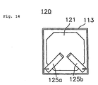
- Fig. 13 is a side view of the multi-mode dielectric filter denoted by reference numeral 120
- Fig. 14 is a plan view thereof. In each of these figures, a shield case is cut away to show the inside of the filter.
- the multi-mode dielectric filter 120 is constituted of a dielectric resonator 121, a supporting base 112 for supporting the dielectric resonator 121, and a metal shield case 113 containing the dielectric resonator 121 and the supporting base 112.
- a loop 125a as an input coupling unit and another loop 125b as an output coupling unit are attached to the shield case 113 so that the loops 125a and 125b are respectively coupled with the dielectric resonator 121.
- the dielectric resonator 121 has a configuration seen as if it were formed by cutting away four corners of a square when observed from above. With this configuration, the dielectric resonator 121 can be used as a triple-mode dielectric resonator, which resonates in three resonant modes shown in Fig. 5, such as the TM 01 ⁇ x+y mode, the TE 01 ⁇ Z mode, and the TM 01 ⁇ x-y mode. In this case, each of the subscripts x, y, and z indicates each of the directions of x, y, and z set as an axial direction.
- the TM 01 ⁇ x+y mode is equivalent to the TM 01 ⁇ mode obtained when the sum of a vector x and a vector y is set as the axial direction.
- the axis z indicates upper and lower directions, and an electric field is indicated by a solid line, whereas a magnetic field is indicated by a broken line.
- the loop 125a as the input coupling unit is positioned in a direction perpendicular to the magnetic field of the TM 01 ⁇ x+y mode so as to couple the loop 125a and the TM 01 ⁇ x+y mode of the dielectric resonator 121. Then, the TM 01 ⁇ x+y mode and the TE 01 ⁇ Z mode are coupled, and furthermore, the TE 01 ⁇ Z mode and the TM 01 ⁇ x-y mode are coupled.
- the TM 01 ⁇ x-y mode of the dielectric resonator 121 is coupled with the loop 125b as the output coupling unit positioned in a direction perpendicular to the magnetic field of the TM 01 ⁇ x-y mode.
- This structure permits the multi-mode dielectric filter 120 to serve as a three-stage band pass filter.
- both the input coupling unit and the output coupling unit are positioned on the upper side of the dielectric resonator.
- the positions of the input coupling unit and the output coupling unit are determined by considering the amount of coupling between the input coupling unit and the dielectric resonator, and the amount of coupling between the output coupling unit and the dielectric resonator.
- a dielectric filter including a shield case having conductivity; a dielectric resonator disposed inside the shield case; a supporting base integrally formed with the dielectric resonator or separately formed therefrom so as to support the dielectric resonator; an input coupling unit and an output coupling unit for coupling to the dielectric resonator; in which one of the input coupling unit and the output coupling unit is a probe with an open-circuited end, the probe extending on a side where the supporting base of the dielectric resonator is disposed.
- the input coupling unit and the output coupling unit When one of the input coupling unit and the output coupling unit extends on the side where the supporting base of the dielectric resonator is disposed, the input coupling unit and the output coupling unit are positioned in such a manner that the units do not give influence on each other. As a result, designing for positioning the input coupling unit and the output coupling unit can be easily performed. Furthermore, since the coupling unit extending on the side where the supporting base is disposed is formed by the probe, it is not necessary to increase the length of the coupling unit in order to obtain a desired amount of coupling, and there is no problem in that the limitation to the length of the coupling unit caused by the presence of the supporting base hinders obtaining of a sufficient amount of coupling.
- the dielectric resonator may be a multi-mode dielectric resonator having at least two resonant modes substantially orthogonal to each other.
- a duplexer including at least two filters; input/output connecting units connected to the filters; and an antenna connecting unit commonly connected to the filters; in which at least one of the filters is the dielectric filter in accordance with the first aspect of the invention.
- a communication apparatus including the duplexer in accordance with the second aspect of the invention; a transmission circuit connected to at least one of the input/output connecting units of the duplexer; a reception circuit connected to at least one of the input/output connecting units, which is not the input/output connecting unit connected to the transmission circuit; and an antenna connected to the antenna connecting unit of the duplexer.
- This arrangement can provide a duplexer and a communication apparatus, in which designing for positioning the input coupling unit and the output coupling unit can be facilitated, and required characteristics can be obtained.
- Fig. 1 is a side view of the dielectric filter of the first embodiment
- Fig. 2 is a plan view thereof.
- a shield case is cut away to show the inside of the filter.
- the dielectric filter denoted by reference numeral 10 is constituted of a cylindrical dielectric resonator 11, a supporting base 12 for supporting the dielectric resonator 11, and a metal shield case 13 containing the dielectric resonator 11 and the supporting base 12.
- a probe 16a as an input coupling unit and a probe 16b as an output coupling unit are attached to the shield case 13, and are positioned in such a manner that the probes 16a and 16b are coupled with the dielectric resonator 11.
- One end of each of the probes 16a and 16b is, for example, connected to the central conductor of a coaxial connector attached to the shield case 13 so as to be connected to an external circuit. In the figures, the central conductor of the coaxial connector is not shown.
- the probe 16a as the input coupling unit extends on the upper side of the dielectric resonator 11, and the probe 16b as the output coupling unit extends on the lower side thereof, that is, on a side where the supporting base 12 is disposed.
- the mutual influence between the input coupling unit and the output coupling unit can be reduced so that there is almost no disturbing influence on each other.
- designing for positioning the input coupling unit and the output coupling unit can be facilitated.
- the output coupling unit is formed by the probe, it is unnecessary to increase the length of the output coupling unit in order to obtain a sufficient amount of coupling.
- the dielectric filter 10 having such a structure, when a signal is inputted from the probe 16a as the input coupling unit, the probe 16a and the TE 01 ⁇ mode are coupled. Sequentially, the dielectric resonator 11 and the probe 16b as the output coupling unit are coupled to output only the signals of a specified frequency band.
- a multi-mode dielectric filter according to a second embodiment of the present invention will be illustrated by referring to Figs. 3 and 4.
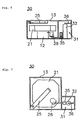
- Fig. 3 is a side view of the multi-mode dielectric filter of the second embodiment
- Fig. 4 is a plan view thereof.
- a shield case is cut away to show the inside of the filter.
- the multi-mode dielectric filter of this embodiment which is denoted by reference numeral 20, is constituted of a dielectric resonator 21, a supporting base 12 for supporting the dielectric resonator 21, and a metal shield case 13 containing the dielectric resonator 21 and the supporting base 12.
- a loop 25 as an input coupling unit and a probe 26 as an output coupling unit are attached to the shield case 13 to be each coupled with the dielectric resonator 21.
- the dielectric resonator 21 has a configuration seen as if it were formed by cutting away four corners of a square when observed from above. With this configuration, the dielectric resonator 21 can be used as a triple-mode dielectric resonator, which resonates in three resonant modes shown in Fig. 5, such as the TM 01 ⁇ x+y mode, the TE 01 ⁇ Z mode, and the TM 01 ⁇ x-y mode.
- the subscripts x, y, and z indicate the directions of x, y, and z set as axial directions.
- the TM 01 ⁇ x+y mode is the TM 01 ⁇ mode obtained when the sum of a vector x and a vector y is set as the axial direction.
- the axis z indicates upper and lower directions, and an electric field is indicated by a solid line, whereas a magnetic field is indicated by a broken line.
- the loop 25 as the input coupling unit extends in a direction perpendicular to the magnetic field of the TM 01 ⁇ x+y mode on the upper side of the dielectric resonator 21.
- the probe 26 as the output coupling unit extends in a direction perpendicular to the magnetic field of the TM 01 ⁇ x-y mode on the lower side of the dielectric resonator 21, that is, on the side where the supporting base 12 is disposed.
- this arrangement can facilitate designing for positioning the input-coupling unit and the output-coupling unit. Furthermore, since the output coupling unit is formed by the probe, it is unnecessary to increase the length of the output coupling unit in order to obtain a sufficient amount of coupling. Therefore, even when the probe 26 is extended in a direction perpendicular to the magnetic world of the TM 01 ⁇ x-y mode, that is, on the side where the supporting base 12 of the dielectric resonator 21 is disposed, the supporting base 12 is not a hindrance. Furthermore, similarly, regarding the loop 25 extending on the upper side of the dielectric resonator 21, there is no need to consider intersecting of the output coupling unit and the loop 25. Accordingly, it is possible to increase the length of the loop 25 to some extent in order to obtain a desired amount of coupling.
- the loop 25 as the input coupling unit and the TM 01 ⁇ x+y mode of the dielectric resonator 21 are coupled.
- the TM 01 ⁇ x+y mode and the TE 01 ⁇ Z mode are coupled, and sequentially, the TE 01 ⁇ Z mode and the TM 01 ⁇ x-y mode are coupled.
- the probe 26 as the output coupling unit and the TM 01 ⁇ x-y mode of the dielectric resonator 21 are coupled so that the multi-mode dielectric filter 20 serves as a three-stage band pass filter.
- Fig. 6 is a side view of the dielectric filter of the third embodiment
- Fig. 7 is a plan view thereof.
- a shield case is cut away to show the inside of the filter.
- the same reference numerals are given to the same parts as those shown in the above embodiments, and the explanation thereof is omitted.
- a triple-mode dielectric resonator 21 and a hollow resonator 31 are disposed by putting a metal plate therebetween so that the dielectric filter 30 serves as a four-stage band pass filter.
- the hollow resonator 31 is formed by disposing a cylindrical conductor 32 with an end connected to a shield case 13 and the other end open-circuited at the center inside the a metal-plate shield case 13. In this situation, the cylindrical conductor 32 is used as a central conductor, and the shield case 13 is used as a ground conductor.
- a loop 25 as an input coupling unit is extended on the upper side of the dielectric resonator 21, and a probe 36 as an output coupling unit is extended on the upper side of the hollow resonator 31.
- an inter-resonator coupling unit formed by a probe 26 and a loop 35 is disposed between the dielectric resonator 21 and the hollow resonator 31.
- the probe 26 of the inter-resonator coupling unit extends on the side where a supporting base 12 of the dielectric resonator 21 is disposed, and the loop 35 extends on the side where the hollow resonator 31 is disposed.
- the four-stage band pass filter is formed by the triple-mode dielectric resonator 21 and the hollow resonator 31.
- a three-stage band pass filter may be formed by the dielectric resonators, and the hollow resonator may be used as a trap.
- a duplexer according to a fourth embodiment of the present invention will be illustrated with reference to Fig. 8.
- Fig. 8 is a plan view of the duplexer of the fourth embodiment, and a shield case is cut away to show the inside of the duplexer.
- the same reference numerals are given to the same parts as those shown in the second embodiment, and the explanation thereof is omitted.
- the duplexer 40 of this embodiment includes a transmission dielectric filter 41 and a reception dielectric filter 42.
- the transmission dielectric filter 41 is formed by disposing two triple-mode dielectric resonators 21a and 21b, between which a metal plate is put
- the reception dielectric filter 42 is formed by disposing two triple-mode dielectric resonators 21c and 21d, between which a metal plate is put.
- the input coupling unit of the transmission dielectric filter 41 is formed by a probe 26a, and is connected to an external transmission circuit.
- the output coupling unit of the reception dielectric filter 42 is formed by a probe 26d, and is connected to an external reception circuit.
- the output coupling unit of the transmission dielectric filter 41 is formed by a prove 26b, and the input coupling unit of the reception dielectric filter 42 is formed by a probe 26c, and both of them are commonly connected to an external antenna.
- the probes 26a and 26c as the input coupling units are extended on sides where supporting bases of the dielectric resonators 21a and 21c are disposed, and the probes 26b and 26d as the output coupling units are extended on sides where the supporting bases of the dielectric resonators 21b and 21d are disposed.
- the loops 25a, 25b, 25c, and 25d are used as the inter-resonator coupling units.
- probes 26a, 26b, 26c, and 26d may be used as inter-resonator coupling units.
- the input coupling unit and the output coupling unit shown in Fig. 8, and the probes 26a, 26b, 26c, and 26d as the inter-resonator coupling units shown in Fig. 9 are equivalent to the input coupling unit and the output coupling unit extending on the side where the supporting base is disposed in the present invention.
- the advantages of the present invention such as facilitated designing for arranging the input/output coupling units and an increase in the amount of coupling can be obtained.
- duplexers 40 and 40a having such structures in accordance with the fourth embodiment, only a signal having a specified frequency is passed by the transmission dielectric filter 41, and a signal having a frequency different from the frequency of the transmission dielectric filter 41 is passed by the reception dielectric filter 42.
- Fig. 10 is a schematic view of a communication apparatus 50 of the fifth embodiment.
- the communication apparatus 50 is constituted of the duplexer 40, a transmission circuit 51, a reception circuit 52, and an antenna 53.
- the duplexer 40 is equivalent to the duplexer shown in the previous embodiment.
- the input coupling unit connected to the transmission dielectric filter 41 shown in Fig. 8 is connected to the transmission circuit 51.
- the output coupling unit connected to the reception dielectric filter 42 shown in Fig. 8 is connected to the reception circuit 52.
- the output coupling unit of the transmission dielectric filter 41 is integrated with the input coupling unit of the reception dielectric filter 42 to be connected to the antenna 53.
- the coupling between the dielectric resonator and the coupling unit is set as an electric-field coupling, it is substantially unnecessary to increase the length of the probe in order to obtain a desired amount of coupling, and there is no problem in that the desired amount of coupling cannot be obtained due to the presence of the supporting base.
- the input coupling unit and the output coupling unit are each oriented toward the center of the dielectric resonator when observed from above.
- one of the coupling units is extended on the side where the supporting base of the dielectric resonator is disposed, it is unnecessary to consider intersection of the input coupling unit and the output coupling unit.
- the probe is used as the coupling unit extending on the side where the supporting base of the dielectric resonator is disposed, it is unnecessary to increase the length of the probe in order to obtain the desired amount of coupling, and the presence of the supporting base is not a hindrance even when the coupling unit is oriented toward the center of the dielectric resonator.
Landscapes
- Control Of Motors That Do Not Use Commutators (AREA)
- Waveguide Switches, Polarizers, And Phase Shifters (AREA)
Abstract
Description
- The present invention relates to dielectric filters, duplexers, and communication apparatuses incorporating the same, which are used in base stations having high-frequency communication apparatuses.
- A conventional
dielectric filter 110 will be illustrated with reference to Figs. 11 and 12. Fig. 11 is a side view of the conventionaldielectric filter 110, and Fig. 12 is a plan view thereof. In these figures, shield cases are cut away to show the inside of thefilter 110. - As shown in Figs. 11 and 12, the conventional
dielectric filter 110 are constituted of a cylindricaldielectric resonator 111, a supportingbase 112 for supporting thedielectric resonator 111, and ametal shield case 113 for containing thedielectric resonator 111 and the supportingbase 112. In addition, aloop 115 as an input coupling unit and aprobe 116 as an output coupling unit are attached to theshield case 113 in such a manner that theloop 115 and theprobe 116, respectively, are coupled to thedielectric resonator 111. - In this arrangement, the
loop 115 is formed by connecting an end of a metal line or a metal plate to theshield case 113 to be grounded, and connecting the other end thereof, for example, to the central conductor of a coaxial connector so as to perform a magnetic-field coupling with thedielectric resonator 111. In general, a loop has a structure in which one end of the loop is connected to a shield case, and the other end thereof is connected to a central conductor to retain both ends of the loop. This structure permits filter characteristics to be stabilized, since the position of the loop does not change due to influence from the outside, and the amount of coupling can be maintained constant. - Meanwhile, regarding a probe, an electric-field coupling is performed between the probe and a dielectric resonator by making an end of a metal line open, and connecting the other end thereof, for example, to the central conductor of a coaxial connector. In the electric-field coupling between the probe and the dielectric resonator, the amount of coupling with the dielectric resonator is larger than the amount of coupling between a dielectric resonator and a loop having the same length as that of the probe.
- In the conventional
dielectric filter 110 having such a structure, a signal is inputted from theloop 115 as the input coupling unit so as to couple theloop 115 with the TE 01δ mode of thedielectric resonator 111. After this, thedielectric resonator 111 and theprobe 116 as the output coupling unit are coupled so as to output only the signals of a specified frequency band. - As an input coupling unit and an output coupling unit, besides the combination of a loop and a probe, the combination of only loops, and the combination of only probes are conventionally known.
- Next, referring to Figs. 13 and 14, a description will be given of a multi-mode dielectric filter proposed by the assignee of the present application in Japanese Patent Application No. 10-220371 which was not laid-open to the public at the time of the priority date of this application. Thus, the disclosures of the drawings as well as the contents of the Japanese application do not constitute the prior art. Fig. 13 is a side view of the multi-mode dielectric filter denoted by
reference numeral 120, and Fig. 14 is a plan view thereof. In each of these figures, a shield case is cut away to show the inside of the filter. - As shown in Figs. 13 and 14, the multi-mode
dielectric filter 120 is constituted of adielectric resonator 121, a supportingbase 112 for supporting thedielectric resonator 121, and ametal shield case 113 containing thedielectric resonator 121 and the supportingbase 112. In addition, aloop 125a as an input coupling unit and anotherloop 125b as an output coupling unit are attached to theshield case 113 so that theloops dielectric resonator 121. - The
dielectric resonator 121 has a configuration seen as if it were formed by cutting away four corners of a square when observed from above. With this configuration, thedielectric resonator 121 can be used as a triple-mode dielectric resonator, which resonates in three resonant modes shown in Fig. 5, such as the TM 01δx+y mode, the TE 01δZ mode, and the TM 01δx-y mode. In this case, each of the subscripts x, y, and z indicates each of the directions of x, y, and z set as an axial direction. For example, the TM 01δx+y mode is equivalent to the TM 01δ mode obtained when the sum of a vector x and a vector y is set as the axial direction. The axis z indicates upper and lower directions, and an electric field is indicated by a solid line, whereas a magnetic field is indicated by a broken line. - In the multi-mode
dielectric resonator 120 having such a structure, theloop 125a as the input coupling unit is positioned in a direction perpendicular to the magnetic field of the TM 01δx+y mode so as to couple theloop 125a and the TM 01δx+y mode of thedielectric resonator 121. Then, the TM 01δx+y mode and the TE 01δZ mode are coupled, and furthermore, the TE 01δZ mode and the TM 01δx-y mode are coupled. Lastly, the TM 01δx-y mode of thedielectric resonator 121 is coupled with theloop 125b as the output coupling unit positioned in a direction perpendicular to the magnetic field of the TM 01δx-y mode. This structure permits the multi-modedielectric filter 120 to serve as a three-stage band pass filter. - In the conventional dielectric filter, both the input coupling unit and the output coupling unit are positioned on the upper side of the dielectric resonator. In this case, the positions of the input coupling unit and the output coupling unit are determined by considering the amount of coupling between the input coupling unit and the dielectric resonator, and the amount of coupling between the output coupling unit and the dielectric resonator.
- However, as shown above, when the input coupling unit and the output coupling unit are relatively closed to each other, a relatively great mutual influence is generated between the input coupling unit and the output coupling unit. Therefore, when the positions for arranging both the input coupling unit and the output coupling unit are determined, it is necessary to consider the mutual influence generated between the coupling units. This makes designing of the filter difficult. Similarly, this problem often occurs in a case in which an input coupling unit and an output coupling unit are disposed on the side positions of the dielectric resonator.
- In contrast, in the multi-mode dielectric filter proposed in Japanese Patent Application No. 10-220371, the two resonant modes orthogonal to each other are coupled to the input coupling unit and the output coupling unit. As a result, in order not to make the input coupling unit and the output coupling unit mutually intersect in a space-limited structure, it is necessary to reduce the lengths of both the input coupling unit and the output coupling unit.
- Meanwhile, in order to increase the amount of coupling between the dielectric resonator and the input coupling unit, and the amount of coupling between the dielectric resonator and the output coupling unit, it is necessary to increase the lengths of the input coupling unit and the output coupling unit. However, in such a dielectric filter, due to a space limitation in the structure, the lengths of the input coupling unit and the output coupling unit must be reduced. Furthermore, the loops are used as the input coupling unit and the output coupling unit. Thus, no great amount of coupling can be obtained. In other words, in the multi-mode dielectric filter proposed in Japanese Patent Application No. 10-220371, in addition to the above problem, when filter characteristics with a broad pass bandwidth are required, it is impossible to increase the amounts of coupling between the dielectric resonator and the respective coupling units. As a result, there is a problem in that no desired filter characteristics can be obtained.
- Accordingly, it is an object of the present invention to solve the above problems and provide a dielectric filter, a duplexer, and a communication apparatus incorporating the same, in which the positions of an input coupling unit and an output coupling unit can be easily arranged, and the amounts of couplings between a dielectric resonator and the coupling units can be sufficiently obtained.
- To this end, according to a first aspect of the present invention, there is provided a dielectric filter including a shield case having conductivity; a dielectric resonator disposed inside the shield case; a supporting base integrally formed with the dielectric resonator or separately formed therefrom so as to support the dielectric resonator; an input coupling unit and an output coupling unit for coupling to the dielectric resonator; in which one of the input coupling unit and the output coupling unit is a probe with an open-circuited end, the probe extending on a side where the supporting base of the dielectric resonator is disposed.
- When one of the input coupling unit and the output coupling unit extends on the side where the supporting base of the dielectric resonator is disposed, the input coupling unit and the output coupling unit are positioned in such a manner that the units do not give influence on each other. As a result, designing for positioning the input coupling unit and the output coupling unit can be easily performed. Furthermore, since the coupling unit extending on the side where the supporting base is disposed is formed by the probe, it is not necessary to increase the length of the coupling unit in order to obtain a desired amount of coupling, and there is no problem in that the limitation to the length of the coupling unit caused by the presence of the supporting base hinders obtaining of a sufficient amount of coupling.
- In addition, in the above dielectric filter, the dielectric resonator may be a multi-mode dielectric resonator having at least two resonant modes substantially orthogonal to each other.
- When the input coupling unit and the output coupling unit are disposed so as to be coupled to the multi-mode dielectric resonator having at least two resonant modes substantially perpendicular to each other, directions in which the input coupling unit and the output coupling unit extend are equivalent to directions toward the center of the dielectric resonator when observed from above. With the structure of this dielectric filter, it is easy to design the positions for arranging the input coupling unit and the output coupling unit and obtain a sufficient amount of coupling. That is, in this dielectric filter, since the input coupling unit and the output coupling unit are disposed away from each other so as to prevent influence on each other, and the coupling unit extending on the side where the supporting base is disposed is formed by the probe, it is not necessary to increase the length of the coupling unit in order to obtain the desired amount of coupling, and the presence of the supporting base does not hinder the extending unit from coupling with the resonator.
- In addition, according to a second aspect of the present invention, there is provided a duplexer including at least two filters; input/output connecting units connected to the filters; and an antenna connecting unit commonly connected to the filters; in which at least one of the filters is the dielectric filter in accordance with the first aspect of the invention.
- In addition, according to a third aspect of the present invention, there is provided a communication apparatus including the duplexer in accordance with the second aspect of the invention; a transmission circuit connected to at least one of the input/output connecting units of the duplexer; a reception circuit connected to at least one of the input/output connecting units, which is not the input/output connecting unit connected to the transmission circuit; and an antenna connected to the antenna connecting unit of the duplexer.
- This arrangement can provide a duplexer and a communication apparatus, in which designing for positioning the input coupling unit and the output coupling unit can be facilitated, and required characteristics can be obtained.
-
- Fig. 1 is a side view of a dielectric filter according to a first embodiment of the present invention;
- Fig. 2 is a plan view of the dielectric filter according to the first embodiment of the present invention;
- Fig. 3 is a side view of a multi-mode dielectric filter according to a second embodiment of the present invention;
- Fig. 4 is a plan view of the multi-mode dielectric filter according to the second embodiment of the present invention;
- Figs. 5A to 5C are views of three modes of a triple-mode dielectric resonator;
- Fig. 6 is a side view of a filter according to a third embodiment of the present invention;
- Fig. 7 is a plan view of the filter according to the third embodiment of the present invention;
- Fig. 8 is a plan view of a duplexer according to a fourth embodiment of the present invention;
- Fig. 9 is a plan view of a modified example of the duplexer according to the fourth embodiment of the present invention;
- Fig. 10 is a schematic view of a communication apparatus according to a fifth embodiment of the present invention;
- Fig. 11 is a side view of a conventional dielectric filter;
- Fig. 12 is a plan view of the conventional dielectric filter;
- Fig. 13 is a side view of a dielectric filter previously proposed by the assignee of the present application; and
- Fig. 14 is a plan view of the dielectric filter previously proposed by the assignee of the present application.
-
- Referring now to Figs. 1 and 2, a description will be given of a dielectric filter according to a first embodiment of the present invention. Fig. 1 is a side view of the dielectric filter of the first embodiment, and Fig. 2 is a plan view thereof. In each of these figures, a shield case is cut away to show the inside of the filter.
- As shown in Figs. 1 and 2, the dielectric filter denoted by
reference numeral 10, in this embodiment, is constituted of a cylindricaldielectric resonator 11, a supportingbase 12 for supporting thedielectric resonator 11, and ametal shield case 13 containing thedielectric resonator 11 and the supportingbase 12. In addition, aprobe 16a as an input coupling unit and aprobe 16b as an output coupling unit are attached to theshield case 13, and are positioned in such a manner that theprobes dielectric resonator 11. One end of each of theprobes shield case 13 so as to be connected to an external circuit. In the figures, the central conductor of the coaxial connector is not shown. - In this case, the
probe 16a as the input coupling unit extends on the upper side of thedielectric resonator 11, and theprobe 16b as the output coupling unit extends on the lower side thereof, that is, on a side where the supportingbase 12 is disposed. When the input coupling unit and the output coupling unit are disposed in such positions, the mutual influence between the input coupling unit and the output coupling unit can be reduced so that there is almost no disturbing influence on each other. As a result, designing for positioning the input coupling unit and the output coupling unit can be facilitated. Furthermore, since the output coupling unit is formed by the probe, it is unnecessary to increase the length of the output coupling unit in order to obtain a sufficient amount of coupling. - In the
dielectric filter 10 having such a structure, when a signal is inputted from theprobe 16a as the input coupling unit, theprobe 16a and the TE 01δ mode are coupled. Sequentially, thedielectric resonator 11 and theprobe 16b as the output coupling unit are coupled to output only the signals of a specified frequency band. - Next, a multi-mode dielectric filter according to a second embodiment of the present invention will be illustrated by referring to Figs. 3 and 4. Fig. 3 is a side view of the multi-mode dielectric filter of the second embodiment, and Fig. 4 is a plan view thereof. A shield case is cut away to show the inside of the filter.
- As shown in Figs. 3 and 4, the multi-mode dielectric filter of this embodiment, which is denoted by
reference numeral 20, is constituted of adielectric resonator 21, a supportingbase 12 for supporting thedielectric resonator 21, and ametal shield case 13 containing thedielectric resonator 21 and the supportingbase 12. In addition, aloop 25 as an input coupling unit and aprobe 26 as an output coupling unit are attached to theshield case 13 to be each coupled with thedielectric resonator 21. - The
dielectric resonator 21 has a configuration seen as if it were formed by cutting away four corners of a square when observed from above. With this configuration, thedielectric resonator 21 can be used as a triple-mode dielectric resonator, which resonates in three resonant modes shown in Fig. 5, such as the TM 01δx+y mode, the TE 01δZ mode, and the TM 01δx-y mode. In this case, the subscripts x, y, and z indicate the directions of x, y, and z set as axial directions. For example, the TM 01δx+y mode is the TM 01δ mode obtained when the sum of a vector x and a vector y is set as the axial direction. The axis z indicates upper and lower directions, and an electric field is indicated by a solid line, whereas a magnetic field is indicated by a broken line. - In the multi-mode
dielectric resonator 21 having such a structure, theloop 25 as the input coupling unit extends in a direction perpendicular to the magnetic field of the TM 01δx+y mode on the upper side of thedielectric resonator 21. Theprobe 26 as the output coupling unit extends in a direction perpendicular to the magnetic field of the TM 01δx-y mode on the lower side of thedielectric resonator 21, that is, on the side where the supportingbase 12 is disposed. By disposing the input coupling unit and the output coupling unit at such positions, the mutual influence between the input coupling unit and the output coupling unit can be reduced so that there is almost no serious problem caused by the influence. Furthermore, this arrangement can facilitate designing for positioning the input-coupling unit and the output-coupling unit. Furthermore, since the output coupling unit is formed by the probe, it is unnecessary to increase the length of the output coupling unit in order to obtain a sufficient amount of coupling. Therefore, even when theprobe 26 is extended in a direction perpendicular to the magnetic world of the TM 01δx-y mode, that is, on the side where the supportingbase 12 of thedielectric resonator 21 is disposed, the supportingbase 12 is not a hindrance. Furthermore, similarly, regarding theloop 25 extending on the upper side of thedielectric resonator 21, there is no need to consider intersecting of the output coupling unit and theloop 25. Accordingly, it is possible to increase the length of theloop 25 to some extent in order to obtain a desired amount of coupling. - In the multi-mode
dielectric filter 20 having such a structure, theloop 25 as the input coupling unit and the TM 01δx+y mode of thedielectric resonator 21 are coupled. Then, the TM 01δx+y mode and the TE 01δZ mode are coupled, and sequentially, the TE 01δZ mode and the TM 01δx-y mode are coupled. Lastly, theprobe 26 as the output coupling unit and the TM 01δx-y mode of thedielectric resonator 21 are coupled so that the multi-modedielectric filter 20 serves as a three-stage band pass filter. - Referring now to Figs. 6 and 7, a description will be given of a dielectric filter according to a third embodiment of the present invention. Fig. 6 is a side view of the dielectric filter of the third embodiment, and Fig. 7 is a plan view thereof. In each of these figures, a shield case is cut away to show the inside of the filter. In addition, the same reference numerals are given to the same parts as those shown in the above embodiments, and the explanation thereof is omitted.
- As shown in Figs. 6 and 7, in the
dielectric filter 30 of this embodiment, a triple-mode dielectric resonator 21 and ahollow resonator 31 are disposed by putting a metal plate therebetween so that thedielectric filter 30 serves as a four-stage band pass filter. Thehollow resonator 31 is formed by disposing acylindrical conductor 32 with an end connected to ashield case 13 and the other end open-circuited at the center inside the a metal-plate shield case 13. In this situation, thecylindrical conductor 32 is used as a central conductor, and theshield case 13 is used as a ground conductor. - In the
filter 30 of the third embodiment, aloop 25 as an input coupling unit is extended on the upper side of thedielectric resonator 21, and aprobe 36 as an output coupling unit is extended on the upper side of thehollow resonator 31. In addition, an inter-resonator coupling unit formed by aprobe 26 and aloop 35 is disposed between thedielectric resonator 21 and thehollow resonator 31. Theprobe 26 of the inter-resonator coupling unit extends on the side where a supportingbase 12 of thedielectric resonator 21 is disposed, and theloop 35 extends on the side where thehollow resonator 31 is disposed. - In this arrangement, since the
probe 26 of the inter-resonator coupling unit extending on the side where thedielectric resonator 21 is disposed can be regarded as the output coupling unit described in the present invention, the same advantages provided in the above embodiments can be obtained in this embodiment. - In the third embodiment of the invention, the four-stage band pass filter is formed by the triple-
mode dielectric resonator 21 and thehollow resonator 31. However, by changing the positions for connecting the input coupling unit and the output coupling unit, a three-stage band pass filter may be formed by the dielectric resonators, and the hollow resonator may be used as a trap. - Furthermore, a duplexer according to a fourth embodiment of the present invention will be illustrated with reference to Fig. 8. Fig. 8 is a plan view of the duplexer of the fourth embodiment, and a shield case is cut away to show the inside of the duplexer. In this duplexer, the same reference numerals are given to the same parts as those shown in the second embodiment, and the explanation thereof is omitted.
- As shown in Fig. 8, the
duplexer 40 of this embodiment includes atransmission dielectric filter 41 and a receptiondielectric filter 42. Thetransmission dielectric filter 41 is formed by disposing two triple-mode dielectric resonators dielectric filter 42 is formed by disposing two triple-mode dielectric resonators - The input coupling unit of the
transmission dielectric filter 41 is formed by aprobe 26a, and is connected to an external transmission circuit. In addition, the output coupling unit of the receptiondielectric filter 42 is formed by aprobe 26d, and is connected to an external reception circuit. The output coupling unit of thetransmission dielectric filter 41 is formed by a prove 26b, and the input coupling unit of the receptiondielectric filter 42 is formed by aprobe 26c, and both of them are commonly connected to an external antenna. Theprobes dielectric resonators probes dielectric resonators - In addition, as inter-resonator coupling units, two
loops transmission dielectric filter 41, and twoloops dielectric filter 42, respectively. - As shown here, in the
duplexer 40 of this embodiment, theloops duplexer 40a shown in Fig. 9,probes - The input coupling unit and the output coupling unit shown in Fig. 8, and the
probes - In the
duplexers transmission dielectric filter 41, and a signal having a frequency different from the frequency of thetransmission dielectric filter 41 is passed by the receptiondielectric filter 42. - In addition, a communication apparatus according to a fifth embodiment of the present invention will be illustrated with reference to Fig. 10. Fig. 10 is a schematic view of a
communication apparatus 50 of the fifth embodiment. - As shown in Fig. 10, the
communication apparatus 50 is constituted of theduplexer 40, atransmission circuit 51, areception circuit 52, and anantenna 53. In this case, theduplexer 40 is equivalent to the duplexer shown in the previous embodiment. The input coupling unit connected to thetransmission dielectric filter 41 shown in Fig. 8 is connected to thetransmission circuit 51. The output coupling unit connected to the receptiondielectric filter 42 shown in Fig. 8 is connected to thereception circuit 52. In addition, the output coupling unit of thetransmission dielectric filter 41 is integrated with the input coupling unit of the receptiondielectric filter 42 to be connected to theantenna 53. - As described above, according to the present invention, in the dielectric filter having an input coupling unit and an output coupling unit, a dielectric resonator supported by a supporting base is disposed inside a shield case. One of the input coupling unit and the output coupling unit is a probe, which is extended on the side where the supporting base of the dielectric resonator is disposed. With this arrangement, when the positioning of the input coupling unit and the output coupling unit is designed, it is unnecessary to consider mutual influence between the input coupling unit and the output coupling unit, so that designing of the positioning can be facilitated. In addition, with the probe, since the coupling between the dielectric resonator and the coupling unit is set as an electric-field coupling, it is substantially unnecessary to increase the length of the probe in order to obtain a desired amount of coupling, and there is no problem in that the desired amount of coupling cannot be obtained due to the presence of the supporting base.
- Particularly, when the dielectric resonator is a multi-mode resonator having two resonant modes perpendicular to each other, the input coupling unit and the output coupling unit are each oriented toward the center of the dielectric resonator when observed from above. However, in the present invention, since one of the coupling units is extended on the side where the supporting base of the dielectric resonator is disposed, it is unnecessary to consider intersection of the input coupling unit and the output coupling unit. Furthermore, since the probe is used as the coupling unit extending on the side where the supporting base of the dielectric resonator is disposed, it is unnecessary to increase the length of the probe in order to obtain the desired amount of coupling, and the presence of the supporting base is not a hindrance even when the coupling unit is oriented toward the center of the dielectric resonator.
- In addition, while the invention has been described in its preferred embodiments, it is to be understood by those skilled in the art that obviously modifications and variations can be made without departing from the scope and spirit of the invention.
Claims (4)
- A dielectric filter (10; 20; 30)comprising:a conductive shield case (13);a dielectric resonator (11; 21) disposed inside the shield case;a supporting base (12) formed in one of an integral fashion and a separate fashion with the dielectric resonator so as to support the dielectric resonator;input coupling unit (16a; 25) and output coupling unit (16b; 26) for coupling to the dielectric resonator;
wherein one of the unit coupling unit and the output coupling element is a probe with an open-circuited end, which extends on a side where the supporting base of the dielectric resonator is disposed. - A dielectric filter according to Claim 1, wherein the dielectric resonator (21) is a multi-mode dielectric resonator having at least two resonant modes approximately orthogonal to each other.
- A duplexer (40; 40a) comprising:at least two filters (41, 42);input/output connecting unit (26a, 26c) connected to the filters; andantenna connecting means (26b, 26d) commonly connected to the filters;
wherein at least one of the filters is the dielectric filter (10; 20; 30) in accordance with claim 1 or 2. - A communication apparatus (50) comprising:the duplexer (40; 40a) in accordance with Claim 3;a transmission circuit (51) connected to at least one of the input/output connecting unit of the duplexer;a reception circuit (52) connected to at least one of the input/output connecting unit which is not connected to the transmission circuit; andan antenna (53) connected to the antenna connecting unit of the duplexer.
Applications Claiming Priority (2)
| Application Number | Priority Date | Filing Date | Title |
|---|---|---|---|
| JP11102964A JP2000295005A (en) | 1999-04-09 | 1999-04-09 | Dielectric filter, duplexer and communication equipment |
| JP10296499 | 1999-04-09 |
Publications (2)
| Publication Number | Publication Date |
|---|---|
| EP1043799A2 true EP1043799A2 (en) | 2000-10-11 |
| EP1043799A3 EP1043799A3 (en) | 2002-04-24 |
Family
ID=14341476
Family Applications (1)
| Application Number | Title | Priority Date | Filing Date |
|---|---|---|---|
| EP00107501A Withdrawn EP1043799A3 (en) | 1999-04-09 | 2000-04-06 | Dielectric filter, duplexer, and communication apparatus |
Country Status (3)
| Country | Link |
|---|---|
| US (1) | US6573812B1 (en) |
| EP (1) | EP1043799A3 (en) |
| JP (1) | JP2000295005A (en) |
Families Citing this family (8)
| Publication number | Priority date | Publication date | Assignee | Title |
|---|---|---|---|---|
| WO2002019458A1 (en) * | 2000-08-29 | 2002-03-07 | Matsushita Electric Industrial Co., Ltd. | Dielectric filter |
| EP1372211A3 (en) * | 2002-06-12 | 2004-01-07 | Matsushita Electric Industrial Co., Ltd. | Dielectric filter, communication apparatus, and method of controlling resonance frequency |
| GB2465522B (en) * | 2007-09-19 | 2012-02-15 | Ngk Spark Plug Co | Dielectric resonator, dielectric resonator filter and method for controlling dielectric resonator |
| US7956707B2 (en) * | 2008-10-21 | 2011-06-07 | Radio Frequency Systems, Inc. | Angled metallic ridge for coupling combline and ceramic resonators |
| US8063723B2 (en) * | 2009-07-01 | 2011-11-22 | Spx Corporation | Filter apparatus and method |
| ES2412394T3 (en) | 2009-07-10 | 2013-07-11 | Kmw Inc. | Multimodal Resonant Filter |
| CN103633402B (en) | 2013-12-16 | 2016-08-17 | 华为技术有限公司 | Duplexer and communication system having the same |
| WO2021045901A1 (en) * | 2019-09-02 | 2021-03-11 | Commscope Technologies Llc | Dielectric tm01 mode resonator |
Citations (1)
| Publication number | Priority date | Publication date | Assignee | Title |
|---|---|---|---|---|
| EP0874414A2 (en) * | 1997-04-21 | 1998-10-28 | Murata Manufacturing Co., Ltd. | Dielectric filter, transmitting/receiving duplexer, and communication apparatus |
Family Cites Families (5)
| Publication number | Priority date | Publication date | Assignee | Title |
|---|---|---|---|---|
| US4453146A (en) * | 1982-09-27 | 1984-06-05 | Ford Aerospace & Communications Corporation | Dual-mode dielectric loaded cavity filter with nonadjacent mode couplings |
| US4963841A (en) * | 1989-05-25 | 1990-10-16 | Raytheon Company | Dielectric resonator filter |
| US5221913A (en) * | 1990-09-26 | 1993-06-22 | Matsushita Electric Industrial Co., Ltd. | Dielectric resonator device with thin plate type dielectric heat-radiator |
| FI97087C (en) * | 1994-10-05 | 1996-10-10 | Nokia Telecommunications Oy | Dielectric resonator |
| JP3344280B2 (en) | 1996-06-25 | 2002-11-11 | 株式会社村田製作所 | Dielectric filter and dielectric duplexer |
-
1999
- 1999-04-09 JP JP11102964A patent/JP2000295005A/en active Pending
-
2000
- 2000-04-06 EP EP00107501A patent/EP1043799A3/en not_active Withdrawn
- 2000-04-06 US US09/543,522 patent/US6573812B1/en not_active Expired - Fee Related
Patent Citations (1)
| Publication number | Priority date | Publication date | Assignee | Title |
|---|---|---|---|---|
| EP0874414A2 (en) * | 1997-04-21 | 1998-10-28 | Murata Manufacturing Co., Ltd. | Dielectric filter, transmitting/receiving duplexer, and communication apparatus |
Also Published As
| Publication number | Publication date |
|---|---|
| US6573812B1 (en) | 2003-06-03 |
| JP2000295005A (en) | 2000-10-20 |
| EP1043799A3 (en) | 2002-04-24 |
Similar Documents
| Publication | Publication Date | Title |
|---|---|---|
| EP1014473B1 (en) | Multi-mode dielectric resonance devices, dielectric filter, composite dielectric filter, synthesizer, distributor, and communication equipment | |
| JP3506104B2 (en) | Resonator device, filter, composite filter device, duplexer, and communication device | |
| EP0104735B1 (en) | Electromagnetic filter with multiple resonant cavities | |
| EP0827233B1 (en) | TM mode dielectric resonator and TM mode dielectric filter and duplexer using the resonator | |
| US12444824B2 (en) | Resonator apparatus, filter apparatus as well as radio frequency and microwave device | |
| US6756865B2 (en) | Resonator device, filter, duplexer, and communication apparatus using the same | |
| US6549102B2 (en) | Quasi dual-mode resonator | |
| US6236288B1 (en) | Dielectric filter having at least one stepped resonator hole with a recessed or protruding portion, the stepped resonator hole extending from a mounting surface | |
| US20080122559A1 (en) | Microwave Filter Including an End-Wall Coupled Coaxial Resonator | |
| US6573812B1 (en) | Dielectric filter, duplexer, and communication apparatus | |
| EP1104044B1 (en) | Multimode dielectric resonator apparatus, filter, duplexer, and communication apparatus | |
| EP0874414B1 (en) | Dielectric filter, transmitting/receiving duplexer, and communication apparatus | |
| EP1104043B1 (en) | Multimode dielectric resonator apparatus, filter, duplexer, and communication apparatus | |
| EP1079457B1 (en) | Dielectric resonance device, dielectric filter, composite dielectric filter device, dielectric duplexer, and communication apparatus | |
| US20020180559A1 (en) | Dielectric resonator loaded metal cavity filter | |
| US6201456B1 (en) | Dielectric filter, dielectric duplexer, and communication device, with non-electrode coupling parts | |
| JP2004312115A (en) | Dielectric resonator apparatus, communication filter, and communication apparatus for mobile communication base station | |
| EP1858109A1 (en) | Dielectric TE dual mode resonator | |
| US7274273B2 (en) | Dielectric resonator device, dielectric filter, duplexer, and high-frequency communication apparatus | |
| US6809615B2 (en) | Band-pass filter and communication apparatus | |
| US6340921B1 (en) | Dielectric filter, dielectric duplexer, and communication apparatus using the same | |
| KR100332155B1 (en) | Multiple Coupling Duplexer with Common Dielectric | |
| JP2004349981A (en) | Resonator device, filter, compound filter device, and communication apparatus | |
| JP2001085908A (en) | Multimode resonator device, filter, composite filter device, duplexer and communication equipment | |
| JPH11312902A (en) | Dielectric filter, transmission/reception equipment and communication equipment |
Legal Events
| Date | Code | Title | Description |
|---|---|---|---|
| PUAI | Public reference made under article 153(3) epc to a published international application that has entered the european phase |
Free format text: ORIGINAL CODE: 0009012 |
|
| 17P | Request for examination filed |
Effective date: 20000406 |
|
| AK | Designated contracting states |
Kind code of ref document: A2 Designated state(s): AT BE CH CY DE DK ES FI FR GB GR IE IT LI LU MC NL PT SE Kind code of ref document: A2 Designated state(s): DE FR GB |
|
| AX | Request for extension of the european patent |
Free format text: AL;LT;LV;MK;RO;SI |
|
| PUAL | Search report despatched |
Free format text: ORIGINAL CODE: 0009013 |
|
| AK | Designated contracting states |
Kind code of ref document: A3 Designated state(s): AT BE CH CY DE DK ES FI FR GB GR IE IT LI LU MC NL PT SE |
|
| AX | Request for extension of the european patent |
Free format text: AL;LT;LV;MK;RO;SI |
|
| AKX | Designation fees paid |
Free format text: DE FR GB |
|
| STAA | Information on the status of an ep patent application or granted ep patent |
Free format text: STATUS: THE APPLICATION HAS BEEN WITHDRAWN |
|
| 18W | Application withdrawn |
Effective date: 20051229 |