EP1043734A2 - Composite electrical insulator, method of assembling same and method of manufacturing same - Google Patents
Composite electrical insulator, method of assembling same and method of manufacturing same Download PDFInfo
- Publication number
- EP1043734A2 EP1043734A2 EP00104148A EP00104148A EP1043734A2 EP 1043734 A2 EP1043734 A2 EP 1043734A2 EP 00104148 A EP00104148 A EP 00104148A EP 00104148 A EP00104148 A EP 00104148A EP 1043734 A2 EP1043734 A2 EP 1043734A2
- Authority
- EP
- European Patent Office
- Prior art keywords
- insulator
- sheath
- end fitting
- metal end
- rod
- Prior art date
- Legal status (The legal status is an assumption and is not a legal conclusion. Google has not performed a legal analysis and makes no representation as to the accuracy of the status listed.)
- Granted
Links
Images


Classifications
-
- H—ELECTRICITY
- H01—ELECTRIC ELEMENTS
- H01B—CABLES; CONDUCTORS; INSULATORS; SELECTION OF MATERIALS FOR THEIR CONDUCTIVE, INSULATING OR DIELECTRIC PROPERTIES
- H01B17/00—Insulators or insulating bodies characterised by their form
- H01B17/32—Single insulators consisting of two or more dissimilar insulating bodies
- H01B17/325—Single insulators consisting of two or more dissimilar insulating bodies comprising a fibre-reinforced insulating core member
-
- Y—GENERAL TAGGING OF NEW TECHNOLOGICAL DEVELOPMENTS; GENERAL TAGGING OF CROSS-SECTIONAL TECHNOLOGIES SPANNING OVER SEVERAL SECTIONS OF THE IPC; TECHNICAL SUBJECTS COVERED BY FORMER USPC CROSS-REFERENCE ART COLLECTIONS [XRACs] AND DIGESTS
- Y10—TECHNICAL SUBJECTS COVERED BY FORMER USPC
- Y10T—TECHNICAL SUBJECTS COVERED BY FORMER US CLASSIFICATION
- Y10T29/00—Metal working
- Y10T29/49—Method of mechanical manufacture
- Y10T29/49002—Electrical device making
- Y10T29/49117—Conductor or circuit manufacturing
- Y10T29/49204—Contact or terminal manufacturing
-
- Y—GENERAL TAGGING OF NEW TECHNOLOGICAL DEVELOPMENTS; GENERAL TAGGING OF CROSS-SECTIONAL TECHNOLOGIES SPANNING OVER SEVERAL SECTIONS OF THE IPC; TECHNICAL SUBJECTS COVERED BY FORMER USPC CROSS-REFERENCE ART COLLECTIONS [XRACs] AND DIGESTS
- Y10—TECHNICAL SUBJECTS COVERED BY FORMER USPC
- Y10T—TECHNICAL SUBJECTS COVERED BY FORMER US CLASSIFICATION
- Y10T29/00—Metal working
- Y10T29/49—Method of mechanical manufacture
- Y10T29/49002—Electrical device making
- Y10T29/49117—Conductor or circuit manufacturing
- Y10T29/49204—Contact or terminal manufacturing
- Y10T29/49208—Contact or terminal manufacturing by assembling plural parts
- Y10T29/49222—Contact or terminal manufacturing by assembling plural parts forming array of contacts or terminals
-
- Y—GENERAL TAGGING OF NEW TECHNOLOGICAL DEVELOPMENTS; GENERAL TAGGING OF CROSS-SECTIONAL TECHNOLOGIES SPANNING OVER SEVERAL SECTIONS OF THE IPC; TECHNICAL SUBJECTS COVERED BY FORMER USPC CROSS-REFERENCE ART COLLECTIONS [XRACs] AND DIGESTS
- Y10—TECHNICAL SUBJECTS COVERED BY FORMER USPC
- Y10T—TECHNICAL SUBJECTS COVERED BY FORMER US CLASSIFICATION
- Y10T29/00—Metal working
- Y10T29/49—Method of mechanical manufacture
- Y10T29/49002—Electrical device making
- Y10T29/49227—Insulator making
Definitions
- the present invention relates generally to the field of composite electrical insulators, and more particularly to methods of assembling and manufacturing a composite electrical insulator comprising an insulator sub-assembly and a metal end fitting, and the resultant composite electrical insulator.
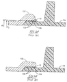
- the metal end fitting 102 has a sleeve portion 106 defining a bore 107 in which the end portion of an FRP rod 108 is received.
- the FRP rod 108 is covered by the sheath 104, which has two circumferential ridges 110 on its outer surface. As shown in FIG. 2A, the circumferential ridges each have an outer diameter (d 2 ).
- the inner diameter (d1) of the bore 107 defined by the sleeve portion 106 is greater than the outer diameter (d2) of the circumferential ridges 110.
- the circumferential ridges 110 served as O-rings which prevented the water from penetrating inside the metal fitting 102. That is, when the sleeve portion 106 of the metal fitting is applied with a moderate crimping force, the circumferential ridges 110 are compressed by the metal fitting 102 into conformity with any unevenness on the inner surface of the metal fitting 102, thereby maintaining the desired water-tightness for a long period.
- one problem with manufacturing an insulator according to this method is that if there is any variance in the dimensioning of the bore 107 and the circumferential ridges 110, the ridges 110 may not completely contact the inner surface of metal fitting 102. Similarly, any eccentricity between the sleeve portion 106 and the bore 107 may result in a gap between the sleeve 106 and ridges 110. In either case, there is a chance water may leak into the gap between the sleeve 106 and the ridges 110. This is dangerous since water may possibly penetrate the boundary between the FRP rod 108 and the sheath 104, and the electrical insulating performance of the insulator will deteriorate so much that electrical discharge (i.e., flashover) will occur.
- the outer diameter (d2) of the circumferential ridges 110 is less than the inner diameter of the bore defined by the metal fitting 102, that portion of the metal fitting 102 overlapping the circumferential ridge 110 must be crimped to compress the ridge 110 and form a good seal.
- This crimping step is in addition to the crimping step used to plastically deform the metal fitting 102 around the FRP rod 108. It would be desirable to eliminate this second crimping step to make the insulator easier and cheaper to assemble.
- It is yet a further object of the present invention is to simplify manufacturing by eliminating the necessity of the second crimping step in assembling a metal end fitting and an insulator sub-assembly.
- the inventor tried making the diameter (d2) of the circumferential ridge greater than the inner diameter (d1) of the bore in the metal end fitting so that the circumferential ridge would form a seal with the inner surface of the metal end fitting without crimping that portion of the metal end fitting that overlaps the ridge.
- a vent created additional manufacturing steps , in that it had to be formed in the metal end fitting and then sealed to prevent water leakage.
- the sealant material would likely break down over time and allow water to enter the interior of the metal end fitting, causing it to rust and destroy the crimping strength of the fitting on the FRP rod, and leading to flashover, as discussed earlier.
- the inventor inserted a spacing member on top of and across the circumferential ridge(s) of the sheath during insertion of the rod/sheath insulator subassembly into the metal end fitting.
- the spacing member deforms the ridge, which is resilient, and provides a temporary venting passageway to allow the air in the cavity to escape when the insulator subassembly is forced into the cavity of the metal end fitting.
- the spacing member is removed.
- the resilient ridge then returns to its original size and shape to form a tight seal between the metal end fitting and the insulator subassembly.
- the spacing member can be of any shape which will temporarily deform the ridge(s) and allow air to escape from the cavity during the insertion step.
- the spacing member could have a hollow tubular construction for allowing the air to vent through the spacing member.
- the spacing member could simply be a cord or wire of sufficient diameter to allow air to vent around the cord or wire and out of the cavity.
- At least one metal end fitting is provided having a sleeve portion which defines a bore with a first diameter, d1.
- An insulator subassembly is then formed.
- the insulator subassembly includes a rod comprising an electrically insulating plastic material, and an insulator sheath covering at least a portion of the outer surface of the rod.
- An end portion of the sheath has a deformable circumferential ridge formed on the outer surface thereof. This circumferential ridge has a second diameter, d2, which is greater than the first diameter, d1.
- the insulator subassembly is then inserted into the bore of the metal end fitting with a spacer member interposed between the metal end fitting and at least the circumferential ridge.
- the spacer member serves to deform the ridge to define a temporary vent for allowing air within the bore to escape.
- the spacer member is then removed thereby allowing the resilient ridge to return to its original size and shape to form a tight seal between the metal end fitting and the insulator subassembly.
- the resultant composite insulator has a construction which includes an insulator subassembly including a rod comprising an electrically insulating plastic material and a sheath covering at least a portion of the outer surface of the rod.
- the sheath has an end portion and at least one deformable circumferential ridge formed on an outer surface thereof The ridge has a second diameter, d2.
- the sheath is made of a resilient and electrically insulating material.
- the composite insulator also includes a metal end fitting having a sleeve portion defining a bore having a diameter, d1, that is less than the second diameter, d2.
- the metal end fitting surrounds the end portion of the sheath, and an end region of the metal end fitting that overlaps the ridge is free from deformation. As a result, it is no longer necessary to crimp the metal end fitting to form a good seal, although the crimping step could be performed if additional tigntness is desired.
- At least one metal end fitting 1 is provided having a sleeve portion 2 which defines a bore 3 with a first diameter, d1.
- the metal end fitting 1 may comprise a high tension steel, aluminum, ductile iron or other appropriate metal, which has been plated by zinc, for example.
- the insulator subassembly 4 is then formed.
- the insulator subassembly 4 includes a rod 5 comprising an electrically insulating plastic material, and an insulator sheath 6, covering at least a portion of the outer surface of rod 5.
- rod 5 is made of a fiber reinforced plastic material.
- This fiber-reinforced plastic material may comprise knitted or woven fibers or bundles of longitudinally oriented fibers, such as glass fibers or other appropriate fibers having a high moduluses of elasticity, and a thermosetting type synthetic resin, such as epoxy resin, polyester resin or the like, impregnated in the fibers as a matrix resin.
- Such fiber reinforced plastic material offers superior mechanical strength and improved resistance to tensile, bending, torsional, and compressive forces. This fiber reinforced plastic material also exhibits an excellent weight to strength ratio.
- sheath 6 when forming the insulator subassembly 4, rod 5 is placed in a mold and sheath 6 is molded around rod 5.
- the end portion 7 of sheath 6 terminates in a generally frustoconical free end having a radially innermost surface region 8 which is axially depressed.
- This axially depressed surface region at the free end of sheath 6 serves to positively prevent separation of sheath 6 from rod 5 upon thermal expansion or cooling shrinkage of sheath 6.
- sheath 6 is made of a resilient and electrically insulating material, such as silicone rubber (preferably) and ethylenepropylene rubber since these materials offer superior weatherability and anti-tracking characteristics.
- the insulating sheath 6 should also include a series of shed portions 9 which are axially spaced from one another to preserve a desired surface leakage distance.
- the end portion 7 of sheath 6 should also include at least one deformable circumferential ridge 10 formed on the outer surface thereof to provide a tight seal with the inner surface of metal fitting 2 defining bore 3.
- the outer surface of sheath 6 may include a plurality of circumferential ridges 10 axially spaced from one another by a predetermined distance.
- all circumferential ridge(s) 10 have a semi-circular cross-section, although any suitable cross-section could be used.
- Each circumferential ridge 10 has a second diameter, d2, which is greater than first diameter, d1.
- the circumferential ridge 10 forms a seal with the inner surface of the metal end fitting 1 without crimping that portion of metal end fitting 1 that overlaps the ridge 10.
- providing this positive seal between the ridge 10 and the metal end fitting 1 eliminates the need for precise dimensional control of the components of the insulator. Accordingly, a good tight water seal can be formed without the need for precise dimensional control over the components of the insulator and without the need for a second crimping step to compress the circumferential ridges.
- a spacer member 20 is interposed between the metal end fitting 2 and the circumferential ridges 10. Since end portion 7 of sheath 6 can have one or more ridges 10, it should be recognized that spacer member 20 must rest on top of and across each circumferential ridge 10 in order to provide a venting passageway during insertion of the subassembly 4 into the metal end fitting 1. It is the spacer member 20 which serves to deform the resilient ridge(s) 10, to allow air in bore 3 to escape when the insulator subassembly 4 is forced into bore 3.
- the spacer member 20 should be made of a material that will not deform when interposed between metal end fitting 1 and circumferential ridge 10.
- spacer member 20 should be made of nylon to prevent damage to ridge 10 when spacer member 20 is removed.
- spacer member 20 can be of any shape which will temporarily deform ridge(s) 10 and allow air to escape from bore 3 during the insertion step.
- the spacer member 20 may have either a hollowed or solid cross-section.
- the spacer member 20 could have a hollow tubular construction for allowing the air to vent through the spacer member.
- the spacer member could simply be a cord or wire of sufficient diameter to allow air to vent around the cord or wire and out of the cavity.
- the cross-sectional shape of the spacer member is round to prevent ridge 10 from tearing.
- any shape could be used so long as it has an adequate radius of curvature to allow air present within bore 3 to escape, and does not damage ridge 10.
- spacer member 20 is removed.
- the resilient ridge 10 then returns to its original size and shape to form a tight seal between metal end fitting 1 and the insulator subassembly 4.
- the resultant composite insulator has a construction which includes an insulator subassembly 4 including a rod 5 comprising an electrically insulating plastic material and a sheath 6 covering at least a portion of the outer surface of rod 5.
- the sheath 6 has an end portion 7 and at least one deformable circumferential ridge 10 formed on an outer surface thereof.
- the ridge 10 has a second diameter, d2.
- the composite insulator also includes a metal end fitting 1 having a sleeve 2 portion defining a bore 3 having a diameter, d1, that is less than the second diameter, d2.
- the metal end fitting 1 surrounds the end portion 7 of sheath 6, and an end region 11 of the metal end fitting 1 that overlaps ridge 10 is free from deformation (i.e., the second crimping step is unnecessary). However, it should be recognized that end region 11 could be crimped to improve water tightness.
- the tightness between sheath 6 and metal fitting 1 may be improved by filling the gap therebetween with a sealant resin, such as silicone rubber.
- At least one metal end fitting is provided having a sleeve portion which defines a bore with a first diameter, d1.
- An insulator subassembly is then formed.
- the insulator subassembly includes a rod of electrically insulating plastic material and an insulator sheath covering at least a portion of the outer surface of the rod.
- An end portion of the sheath has a deformable circumferential ridge formed on the outer surface thereof. This circumferential ridge has a second diameter, d2, which is greater than the first diameter, d1.
- the insulator subassembly is then inserted into the bore of the metal end fitting with a spacer member interposed between the metal end fitting and at least the circumferential ridge.
- the spacer member serves to deform the ridge to define a temporary vent for allowing air within the bore to escape.
- the spacer member is then removed thereby allowing the resilient ridge to return to its original size and shape to form a tight seal between the metal end fitting and the insulator subassembly.
- the resultant composite insulator has a construction which includes an insulator subassembly including a rod and a sheath covering at least a portion of the outer surface of the rod.
- the sheath has an end portion and at least one deformable circumferential ridge formed on an outer surface thereof.
- the composite insulator also includes a metal end fitting having a sleeve portion that surrounds the end portion of the sheath. An end region of the metal end fitting that overlaps the ridge is free from deformation. As a result, it is no longer necessary to crimp the metal end fitting to form a good seal, although the crimping step could be performed if additional tightness is desired.
Landscapes
- Insulators (AREA)
- Insulating Bodies (AREA)
Abstract
Description
Claims (14)
- A method of assembling a composite electrical insulator, comprising the steps of:providing at least one metal end fitting having a sleeve portion defining a bore with a first diameter, d1;providing an insulator subassembly including a rod comprising an electrically insulating plastic material, and an insulator sheath covering at least a portion of the outer surface of said rod, an end portion of said sheath having a deformable circumferential ridge formed on the outer surface thereof, said circumferential ridge having a second diameter, d2, greater than said first diameter, d1;inserting said insulator subassembly into said bore of said metal end fitting with a spacer member interposed between said metal end fitting and at least said circumferential ridge, whereby said spacer member deforms said ridge to define a temporary vent for allowing air within said bore to escape; andremoving said spacer member.
- The method of claim 1, wherein said spacer member comprises a hollow cylindrical tube.
- The method of claim 1, wherein said spacer member comprises a solid cylindrical cord.
- A method of manufacturing a composite electrical insulator assembly, comprising the steps of:forming an insulator subassembly including a rod comprising an electrically insulating plastic material, and an insulator sheath covering at least a portion of the outer surface of said rod, an end portion of said sheath having a deformable circumferential ridge formed on the outer surface thereof;providing at least one metal end fitting having a bore with a first diameter, d1inserting said insulator subassembly into said bore of said metal end fitting with a spacer member interposed between said metal end fitting and at least said circumferential ridge, whereby said spacer member deforms said ridge to define a temporary vent for allowing air within said bore to escape; andremoving said spacer member.
- The method of claim 4, wherein said rod is placed in a mold and said sheath is molded around said rod.
- The method of claim 4, wherein said spacer member comprises a hollow cylindrical tube.
- The method of claim 4, wherein said spacer member comprises a solid cylindrical cord.
- A composite electrical insulator, comprising:an insulator subassembly including a rod comprising an electrically insulating plastic material, and a sheath covering at least a portion of the outer surface of said rod, said sheath having an end portion and at least one deformable circumferential ridge formed on an outer surface thereof, said ridge having a second diameter, d2; anda metal end fitting having a sleeve portion defining a bore having a diameter, d1, that is less than said second diameter, d2, wherein said metal end fitting surrounds the end portion of said sheath and an end region of said metal end fitting that overlaps said ridge is free from deformation.
- The composite electrical insulator of claim 8, wherein said sheath comprises a resilient and electrically insulating material.
- The composite electrical insulator of claim 8, wherein said outer surface of said sheath comprises a plurality of circumferential ridges axially spaced from one another by a predetermined distance.
- The composite electrical insulator of claim 8, wherein said at least one circumferential ridge has a semi-circular cross-section.
- The composite electrical insulator of claim 8, wherein said end portion of said sheath terminates in a generally frustoconical free end having a radially innermost surface region which is axially depressed.
- The composite electrical insulator of claim 8, wherein said metal end fitting further comprises an end region adjacent said end portion of said sheath, and said insulator further comprises a sealant resin interposed between an inner surface of said end region and said outer surface of said sheath.
- The insulator of claim 8, wherein said rod comprises a fiber reinforced plastic material.
Applications Claiming Priority (2)
| Application Number | Priority Date | Filing Date | Title |
|---|---|---|---|
| US288928 | 1999-04-09 | ||
| US09/288,928 US6282783B1 (en) | 1999-04-09 | 1999-04-09 | Composite electrical insulator, method of assembling same and method of manufacturing same |
Publications (3)
| Publication Number | Publication Date |
|---|---|
| EP1043734A2 true EP1043734A2 (en) | 2000-10-11 |
| EP1043734A3 EP1043734A3 (en) | 2001-03-21 |
| EP1043734B1 EP1043734B1 (en) | 2005-05-04 |
Family
ID=23109262
Family Applications (1)
| Application Number | Title | Priority Date | Filing Date |
|---|---|---|---|
| EP00104148A Expired - Lifetime EP1043734B1 (en) | 1999-04-09 | 2000-02-29 | Composite electrical insulator, method of assembling the same and method of manufacturing the same |
Country Status (6)
| Country | Link |
|---|---|
| US (2) | US6282783B1 (en) |
| EP (1) | EP1043734B1 (en) |
| JP (1) | JP4038317B2 (en) |
| CN (1) | CN1197095C (en) |
| DE (1) | DE60019840T2 (en) |
| HU (1) | HU225572B1 (en) |
Cited By (1)
| Publication number | Priority date | Publication date | Assignee | Title |
|---|---|---|---|---|
| EP1205948A4 (en) * | 2000-03-29 | 2006-05-10 | Ngk Insulators Ltd | Method for manufacturing polymer insulator and its end part machining apparatus |
Families Citing this family (6)
| Publication number | Priority date | Publication date | Assignee | Title |
|---|---|---|---|---|
| US6472604B2 (en) * | 2000-03-13 | 2002-10-29 | Ngk Insulators, Ltd. | Seal construction of polymer insulator |
| KR100390640B1 (en) * | 2001-05-15 | 2003-07-07 | 주식회사 에이피케이 | insulator |
| ITAN20060047A1 (en) * | 2006-07-28 | 2008-01-29 | Merloni Termosanitari Spa | DEVICE CONSISTING OF MODULAR SCREWS FOR ELECTRIC PIPE INSULATION |
| US7709743B2 (en) * | 2007-10-15 | 2010-05-04 | Hubbell Incorporated | Integrated insulator seal and shield assemblies |
| CN103883572B (en) * | 2014-03-14 | 2017-01-25 | 上海昀泰机电科技有限公司 | Two-stage curve flexible pressing connecting hydraulic control method for fragile materials |
| CN114448560B (en) * | 2020-11-06 | 2024-08-27 | 深圳市中兴微电子技术有限公司 | A communication chip and data processing method |
Family Cites Families (5)
| Publication number | Priority date | Publication date | Assignee | Title |
|---|---|---|---|---|
| JPS5673821A (en) | 1979-11-17 | 1981-06-18 | Ngk Insulators Ltd | Synthetic resin insulator |
| JP2664616B2 (en) | 1993-03-25 | 1997-10-15 | 日本碍子株式会社 | Airtight structure of non-ceramic insulator |
| JP2610092B2 (en) * | 1993-03-25 | 1997-05-14 | 日本碍子株式会社 | Non-ceramic insulator metal fitting holding structure and metal fitting holding method |
| JP2938801B2 (en) * | 1996-03-18 | 1999-08-25 | 日本碍子株式会社 | Manufacturing method of composite insulator and retaining ring of core rod to mold |
| US6010348A (en) * | 1997-05-20 | 2000-01-04 | Alden Products Company | Field-assembled two-piece snap-fit self-sealed electrical connector |
-
1999
- 1999-04-09 US US09/288,928 patent/US6282783B1/en not_active Expired - Lifetime
-
2000
- 2000-02-29 DE DE60019840T patent/DE60019840T2/en not_active Expired - Lifetime
- 2000-02-29 EP EP00104148A patent/EP1043734B1/en not_active Expired - Lifetime
- 2000-03-06 JP JP2000059991A patent/JP4038317B2/en not_active Expired - Fee Related
- 2000-04-07 HU HU0001418A patent/HU225572B1/en unknown
- 2000-04-10 CN CN00106471.1A patent/CN1197095C/en not_active Expired - Lifetime
-
2001
- 2001-02-27 US US09/794,798 patent/US6384338B2/en not_active Expired - Lifetime
Cited By (1)
| Publication number | Priority date | Publication date | Assignee | Title |
|---|---|---|---|---|
| EP1205948A4 (en) * | 2000-03-29 | 2006-05-10 | Ngk Insulators Ltd | Method for manufacturing polymer insulator and its end part machining apparatus |
Also Published As
| Publication number | Publication date |
|---|---|
| US6282783B1 (en) | 2001-09-04 |
| EP1043734B1 (en) | 2005-05-04 |
| EP1043734A3 (en) | 2001-03-21 |
| HUP0001418A2 (en) | 2001-02-28 |
| CN1197095C (en) | 2005-04-13 |
| DE60019840T2 (en) | 2006-01-19 |
| HUP0001418A3 (en) | 2002-03-28 |
| JP4038317B2 (en) | 2008-01-23 |
| JP2000294056A (en) | 2000-10-20 |
| DE60019840D1 (en) | 2005-06-09 |
| HU0001418D0 (en) | 2000-06-28 |
| US20010009200A1 (en) | 2001-07-26 |
| HU225572B1 (en) | 2007-03-28 |
| US6384338B2 (en) | 2002-05-07 |
| CN1270395A (en) | 2000-10-18 |
Similar Documents
| Publication | Publication Date | Title |
|---|---|---|
| EP0617433B1 (en) | Composite electrical insulator | |
| US6972378B2 (en) | Composite insulator | |
| AU671524B2 (en) | Metal fitting for composite insulators | |
| CA2145619C (en) | Composite insulators and a process for producing the same | |
| EP1043734B1 (en) | Composite electrical insulator, method of assembling the same and method of manufacturing the same | |
| CA2119830C (en) | Composite electrical insulator and method of manufacturing same | |
| US5973272A (en) | Composite insulator with insulating tapered rings providing a transition surface between endpieces and support inserted with the endpieces, a method of manufacturing such an insulator, and apparatus for implementing the method | |
| US5414218A (en) | Arrangement for cable tensile strain relief | |
| US6031186A (en) | Solid polymer insulators with eye and clevis ends | |
| US6065207A (en) | Composite insulators and a process for producing the same | |
| ITMI951832A1 (en) | ASSEMBLY AND ROTOR PROCEDURE OF AN ELECTRIC MOTOR | |
| AU617156B2 (en) | A sleeve of plastic sheet material for a cable termination, a cable splice or another cable portion freed from the cable sheet of electric cable | |
| GB2104171A (en) | Method of joining an insulating rod to a metal end piece | |
| KR200409094Y1 (en) | Polymer Suspension Insulator | |
| US5907898A (en) | Securing method | |
| CN212359301U (en) | Insulating cross arm and power transmission pole | |
| JP2610093B2 (en) | Non-ceramic insulator and method for manufacturing the same | |
| US6778374B2 (en) | Reinforced arrester housing | |
| JPH06233439A (en) | Rubber-molded cable head | |
| AU2004100256A4 (en) | Breakout termination | |
| JPH11312421A (en) | FRP cylinder for polymer SP insulator and method of manufacturing the same | |
| JP2002117737A (en) | Composite insulator | |
| MXPA97010348A (en) | A stopper with a thermoplastic envelope that has a realized outer surface |
Legal Events
| Date | Code | Title | Description |
|---|---|---|---|
| PUAI | Public reference made under article 153(3) epc to a published international application that has entered the european phase |
Free format text: ORIGINAL CODE: 0009012 |
|
| 17P | Request for examination filed |
Effective date: 20000229 |
|
| AK | Designated contracting states |
Kind code of ref document: A2 Designated state(s): DE FR |
|
| AX | Request for extension of the european patent |
Free format text: AL;LT;LV;MK;RO;SI |
|
| PUAL | Search report despatched |
Free format text: ORIGINAL CODE: 0009013 |
|
| AK | Designated contracting states |
Kind code of ref document: A3 Designated state(s): AT BE CH CY DE DK ES FI FR GB GR IE IT LI LU MC NL PT SE |
|
| AX | Request for extension of the european patent |
Free format text: AL;LT;LV;MK;RO;SI |
|
| AKX | Designation fees paid |
Free format text: DE FR |
|
| 17Q | First examination report despatched |
Effective date: 20040121 |
|
| GRAP | Despatch of communication of intention to grant a patent |
Free format text: ORIGINAL CODE: EPIDOSNIGR1 |
|
| RTI1 | Title (correction) |
Free format text: COMPOSITE ELECTRICAL INSULATOR, METHOD OF ASSEMBLING THE SAME AND METHOD OF MANUFACTURING THE SAME |
|
| GRAS | Grant fee paid |
Free format text: ORIGINAL CODE: EPIDOSNIGR3 |
|
| GRAA | (expected) grant |
Free format text: ORIGINAL CODE: 0009210 |
|
| AK | Designated contracting states |
Kind code of ref document: B1 Designated state(s): DE FR |
|
| REF | Corresponds to: |
Ref document number: 60019840 Country of ref document: DE Date of ref document: 20050609 Kind code of ref document: P |
|
| PLBE | No opposition filed within time limit |
Free format text: ORIGINAL CODE: 0009261 |
|
| STAA | Information on the status of an ep patent application or granted ep patent |
Free format text: STATUS: NO OPPOSITION FILED WITHIN TIME LIMIT |
|
| 26N | No opposition filed |
Effective date: 20060207 |
|
| EN | Fr: translation not filed | ||
| PG25 | Lapsed in a contracting state [announced via postgrant information from national office to epo] |
Ref country code: FR Free format text: LAPSE BECAUSE OF FAILURE TO SUBMIT A TRANSLATION OF THE DESCRIPTION OR TO PAY THE FEE WITHIN THE PRESCRIBED TIME-LIMIT Effective date: 20050504 |
|
| PGFP | Annual fee paid to national office [announced via postgrant information from national office to epo] |
Ref country code: DE Payment date: 20190212 Year of fee payment: 20 |
|
| REG | Reference to a national code |
Ref country code: DE Ref legal event code: R071 Ref document number: 60019840 Country of ref document: DE |