EP1043713A2 - Optical recording medium - Google Patents
Optical recording medium Download PDFInfo
- Publication number
- EP1043713A2 EP1043713A2 EP00107003A EP00107003A EP1043713A2 EP 1043713 A2 EP1043713 A2 EP 1043713A2 EP 00107003 A EP00107003 A EP 00107003A EP 00107003 A EP00107003 A EP 00107003A EP 1043713 A2 EP1043713 A2 EP 1043713A2
- Authority
- EP
- European Patent Office
- Prior art keywords
- tracks
- land
- recording medium
- optical recording
- prepits
- Prior art date
- Legal status (The legal status is an assumption and is not a legal conclusion. Google has not performed a legal analysis and makes no representation as to the accuracy of the status listed.)
- Granted
Links
Images


Classifications
-
- G—PHYSICS
- G11—INFORMATION STORAGE
- G11B—INFORMATION STORAGE BASED ON RELATIVE MOVEMENT BETWEEN RECORD CARRIER AND TRANSDUCER
- G11B7/00—Recording or reproducing by optical means, e.g. recording using a thermal beam of optical radiation by modifying optical properties or the physical structure, reproducing using an optical beam at lower power by sensing optical properties; Record carriers therefor
- G11B7/007—Arrangement of the information on the record carrier, e.g. form of tracks, actual track shape, e.g. wobbled, or cross-section, e.g. v-shaped; Sequential information structures, e.g. sectoring or header formats within a track
- G11B7/00745—Sectoring or header formats within a track
-
- G—PHYSICS
- G11—INFORMATION STORAGE
- G11B—INFORMATION STORAGE BASED ON RELATIVE MOVEMENT BETWEEN RECORD CARRIER AND TRANSDUCER
- G11B7/00—Recording or reproducing by optical means, e.g. recording using a thermal beam of optical radiation by modifying optical properties or the physical structure, reproducing using an optical beam at lower power by sensing optical properties; Record carriers therefor
- G11B7/007—Arrangement of the information on the record carrier, e.g. form of tracks, actual track shape, e.g. wobbled, or cross-section, e.g. v-shaped; Sequential information structures, e.g. sectoring or header formats within a track
-
- G—PHYSICS
- G11—INFORMATION STORAGE
- G11B—INFORMATION STORAGE BASED ON RELATIVE MOVEMENT BETWEEN RECORD CARRIER AND TRANSDUCER
- G11B7/00—Recording or reproducing by optical means, e.g. recording using a thermal beam of optical radiation by modifying optical properties or the physical structure, reproducing using an optical beam at lower power by sensing optical properties; Record carriers therefor
- G11B7/24—Record carriers characterised by shape, structure or physical properties, or by the selection of the material
- G11B7/2407—Tracks or pits; Shape, structure or physical properties thereof
- G11B7/24073—Tracks
- G11B7/24079—Width or depth
-
- G—PHYSICS
- G11—INFORMATION STORAGE
- G11B—INFORMATION STORAGE BASED ON RELATIVE MOVEMENT BETWEEN RECORD CARRIER AND TRANSDUCER
- G11B7/00—Recording or reproducing by optical means, e.g. recording using a thermal beam of optical radiation by modifying optical properties or the physical structure, reproducing using an optical beam at lower power by sensing optical properties; Record carriers therefor
- G11B7/24—Record carriers characterised by shape, structure or physical properties, or by the selection of the material
- G11B7/2407—Tracks or pits; Shape, structure or physical properties thereof
- G11B7/24073—Tracks
- G11B7/24082—Meandering
-
- G—PHYSICS
- G11—INFORMATION STORAGE
- G11B—INFORMATION STORAGE BASED ON RELATIVE MOVEMENT BETWEEN RECORD CARRIER AND TRANSDUCER
- G11B7/00—Recording or reproducing by optical means, e.g. recording using a thermal beam of optical radiation by modifying optical properties or the physical structure, reproducing using an optical beam at lower power by sensing optical properties; Record carriers therefor
- G11B7/24—Record carriers characterised by shape, structure or physical properties, or by the selection of the material
- G11B7/2407—Tracks or pits; Shape, structure or physical properties thereof
- G11B7/24085—Pits
-
- G—PHYSICS
- G11—INFORMATION STORAGE
- G11B—INFORMATION STORAGE BASED ON RELATIVE MOVEMENT BETWEEN RECORD CARRIER AND TRANSDUCER
- G11B7/00—Recording or reproducing by optical means, e.g. recording using a thermal beam of optical radiation by modifying optical properties or the physical structure, reproducing using an optical beam at lower power by sensing optical properties; Record carriers therefor
- G11B7/007—Arrangement of the information on the record carrier, e.g. form of tracks, actual track shape, e.g. wobbled, or cross-section, e.g. v-shaped; Sequential information structures, e.g. sectoring or header formats within a track
- G11B2007/00709—Dimensions of grooves or tracks, e.g. groove depth, track pitch
-
- Y—GENERAL TAGGING OF NEW TECHNOLOGICAL DEVELOPMENTS; GENERAL TAGGING OF CROSS-SECTIONAL TECHNOLOGIES SPANNING OVER SEVERAL SECTIONS OF THE IPC; TECHNICAL SUBJECTS COVERED BY FORMER USPC CROSS-REFERENCE ART COLLECTIONS [XRACs] AND DIGESTS
- Y10—TECHNICAL SUBJECTS COVERED BY FORMER USPC
- Y10T—TECHNICAL SUBJECTS COVERED BY FORMER US CLASSIFICATION
- Y10T428/00—Stock material or miscellaneous articles
- Y10T428/21—Circular sheet or circular blank
Definitions
- the present invention relates to an optical recording medium which allows a user to record information data.
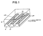
- Fig. 1 is a perspective view illustrating the structure of a recording surface and a cross section of a DVD-R or a DVD-RW (hereinafter simply referred to as the "DVD") before information data is recorded thereon.
- DVD DVD-R or DVD-RW
- convex (when viewed from the view point of the figure) groove tracks GV and concave (similarly, when viewed from the view point of the figure) land tracks LD are spirally or concentrically formed in alternation on a recording layer R of the DVD.
- the DVD has a trasparent substrate B which attaches to the recording layer R at the substrate's surface having the groove and land tracks.
- the land tracks LD are provided with a plurality of previously formed land prepits LPP for use by a DVD recorder (not shown) as addresses for recognizing particular positions on the groove tracks GV and as a recording timing when the DVD recorder records information data (audio data, video data, and computer data).
- Each of the land prepit LPP is formed to connect two adjacent groove tracks GV, and its bottom surface (indicated by hatching) is continuous with the bottom surfaces (similarly, indicated by hatching) of associated groove tracks.
- the DVD recorder For recording information data on the DVD as described above, the DVD recorder irradiates a recording beam to the bottom surfaces of groove tracks GV in accordance with the information data. In this process, heat is conducted over a region of the groove tracks GV irradiated with the recording beam, causing the formation of data pits PT in the heated region as illustrated in Fig. 2. In other words, trains of data pits carrying the information data are formed on the groove tracks GV.
- a deformed information pit PTX is formed as illustrated in Fig. 2. This is because the heat generated when the recording beam is irradiated also affects a portion of the land prepit LPP.
- waveform distortion occurs particularly in a read signal generated by reading the above-mentioned deformed pit PTX, resulting in a higher read error rate.
- the present invention has been made in view of the problem mentioned above, and an object is to provide an optical recording medium which is capable of producing a read signal less waveform distortion when information is reproduced therefrom.
- An optical recording medium is formed with information tracks on which data pits carrying information data is to be formed, and prepit tracks previously formed with a plurality of prepits.
- the information tracks and the prepit tracks are formed adjacent to each other, and at least a bottom part of each of the prepits is formed spaced apart from the information tracks.
- Fig. 3 is a perspective view illustrating the structure of a recording surface and a cross section of a write-once or rewritable DVD according to the present invention as an optical recording medium.
- Fig. 3 illustrates the configuration of the DVD before information data is recorded by a DVD recorder (not shown).
- the recording surface of the DVD is spirally or concentrically formed with convex (when viewed from the view point of the figure) groove tracks GV and concave (similarly, when viewed from the view point of the figure) land tracks LD in alternation.
- the DVD has a transparent substrate B which attaches to the recording layer R at the substrate's surface having the groove and land tracks.
- the land tracks LD in turn are previously formed sporadically with a plurality of isolated land prepits LPP' serving as addresses for recognizing particular positions on the groove tracks GV, and recording timing which are used by the DVD recorder when it records information data on the DVD.
- each of the land prepits is formed, as can be seen in Figs. 3 and 4, as an isolated or island-like land prepit LPP' that is formed to be spaced apart from each of two adjacent groove tracks GV by a predetermined distance.
- the width W 2 of the land prepit LPP' in the disc's radial direction is made narrower than the width W 3 of the land track LD as shown in Fig. 4, thereby the land prepits LPP' is formed as an isolated land prepit which is separated from the groove tracks GV.
- the width of the groove tracks GV is denoted by W 1 .
- the isolated land prepits LPP thus formed will not affected by head generated by a recording beam in accordance with information data, for example, even if a portion of a groove track GV close to a land prepit LPP' is irradiated therewith.
- recorded data pits PT can be formed even near the land prepits LPP' on the groove track GV without suffering from deformation.
- a master disc which is formed with concave groove tracks GV and isolated prepits LPP'.
- the creation of this master disc involves creating a mask pattern having the respective groove tracks GV and isolated land prepits LPP' in the illustrated configuration by laser cutting.
- the width of the land prepit LPP' in the radial direction of the disc should be smaller than the track pitch of the groove tracks GV.
- the creation of the mask pattern for the land prepits LPP' requires a cutting beam having a smaller diameter than that which is irradiated for creating the mask pattern for the groove tracks GV.
- Fig. 5 illustrates an exemplary configuration of an LPP cutting beam generator which may be used to create the mask pattern for the land prepits LPP'.
- laser light generated by a laser oscillator 50 is directed to an objective lens 52 through a laser intensity distribution correcting element 51.
- the laser intensity distribution correcting element 51 consists of a transmitting area 51b which transmits the laser beam, and a blocking area 51a which blocks the same.
- the blocking area 51a is positioned such that its center substantially matches the center of the laser light.
- the objective lens 52 converges the laser light directed thereto through the laser strength distribution correcting element 51, and irradiates a mask material (not shown) with the converged laser light as a cutting beam. Since the intensity of the laser light is reduced in a central portion by the laser intensity distribution correcting element 51 as compared with a peripheral portion, the laser beam converged by the objective lens 52 is reduced in beam diameter.
- the LPP cutting beam generator illustrated in Fig. 5 utilizes a super-resolution phenomenon to reduce the beam diameter of the cutting beam.
- the DVD shown in the foregoing embodiment is formed with convex groove tracks GV and concave land tracks LD, their shapes may be reversed. Specifically, the DVD may be formed with concave groove tracks GV and convex land tracks LD. With such a DVD, data pits PT carrying information data will be formed on the land tracks LD, while isolated groove prepits are previously formed on the groove tracks GV in place of the land prepits LPP'.
- Fig. 6 shows another example of the land prepits LPP'.
- the land prepits LPP' are formed at similar positions as those of the land prepits LPP' shown in Fig. 3.
- Fig. 6 and Fig. 7 showing a cross-section taken along the line VII-VII in Fig. 6, each of the land prepits LPP' is formed in a manner that a bottom part thereof is spaced apart from the groove tracks GV, while the land prepit LPP' connects to the groove tracks GV at about a middle postion in its depth.
- Fig. 6 shows another example of the land prepits LPP'.
- the land prepits LPP' are formed at similar positions as those of the land prepits LPP' shown in Fig. 3.
- Fig. 7 showing a cross-section taken along the line VII-VII in Fig. 6
- each of the land prepits LPP' is formed in a manner that a bottom part thereof is spaced apart from the groove tracks GV, while the land prepit LPP' connects to
- the width W 2 of the bottom part of the land prepit LPP' in a radial direction of the disc is made smaller than the width W 3 of the landtrack LD, that is, the width of the space between a pair of groove tracks GV.
- the bottom part of each of the land prepits LPP' is spaced apart from the groove tracks GV.
- the land prepits LPP' shown in Figs. 6 and 7 are formed by reducing the diameter of the cutting beam in a manner similar to that explained by referring to Fig. 5.
- the height of the wall formed between the groove track GV and the land prepit LPP' is lower than that in the embodiment shown in Fig. 3.
- the effect to prevent conduction of heat generated by the irradiation of the recording beam to the land prepit LPP' becomes smaller in the configuration shown in Figs. 6 and 7, an advantage exists that the substrate B can be formed relatively easily.
- variation of the height of the wall that defines the side face of a land prepit becomes small among the disks, so that the uniformity of a land prepit reading signal can be improved.
- the optical recording medium of the present invention since prepits are not affected by the heat generated by a recording beam irradiated in accordance with information data, data pits carrying information data are formed in normal shape. Thus, a read signal free from waveform distortion is advantageously produced from the optical recording medium.
- each of the land prepits LPP' is formed spaced apart from two groove tracks GV which sandwich it.
- each of the land prepits LPP' can be formed spaced apart from only one of the two groove tracks GV and connected to the remaining one of the groove tracks GV.
Landscapes
- Optical Recording Or Reproduction (AREA)
- Optical Record Carriers And Manufacture Thereof (AREA)
Abstract
Description
Claims (2)
- An optical recording medium comprising:information tracks on which data pits carrying information data is to be formed; andprepit tracks previously formed with a plurality of prepits,
wherein each of said information tracks is formed adjacent to each of said prepit tracks, and at least a bottom part of each of said prepits is formed spaced apart from at least one of said information tracks. - An optical recording medium according to claim 1, wherein said information tracks are groove tracks on said optical recording medium, said prepit tracks are land tracks on said optical recording medium, and said prepits are land prepits on said optical recording medium.
Applications Claiming Priority (2)
| Application Number | Priority Date | Filing Date | Title |
|---|---|---|---|
| JP10146599 | 1999-04-08 | ||
| JP10146599 | 1999-04-08 |
Publications (3)
| Publication Number | Publication Date |
|---|---|
| EP1043713A2 true EP1043713A2 (en) | 2000-10-11 |
| EP1043713A3 EP1043713A3 (en) | 2002-01-30 |
| EP1043713B1 EP1043713B1 (en) | 2007-05-09 |
Family
ID=14301471
Family Applications (1)
| Application Number | Title | Priority Date | Filing Date |
|---|---|---|---|
| EP00107003A Expired - Lifetime EP1043713B1 (en) | 1999-04-08 | 2000-03-30 | Optical recording medium |
Country Status (6)
| Country | Link |
|---|---|
| US (1) | US6599607B1 (en) |
| EP (1) | EP1043713B1 (en) |
| KR (1) | KR100414875B1 (en) |
| CN (1) | CN1137468C (en) |
| DE (1) | DE60034734T2 (en) |
| TW (1) | TW526480B (en) |
Families Citing this family (8)
| Publication number | Priority date | Publication date | Assignee | Title |
|---|---|---|---|---|
| DE60033464T2 (en) * | 1999-04-08 | 2007-10-04 | Pioneer Corporation | Optical recording medium |
| JP4136293B2 (en) * | 2000-08-10 | 2008-08-20 | パイオニア株式会社 | Optical recording medium, manufacturing method and manufacturing apparatus |
| TW564416B (en) * | 2000-09-12 | 2003-12-01 | Tdk Corp | Optical recording medium |
| JP4278855B2 (en) * | 2000-11-01 | 2009-06-17 | パイオニア株式会社 | Rewritable optical disc and method and system for manufacturing the same |
| US6819650B2 (en) * | 2001-01-12 | 2004-11-16 | Victor Company Of Japan, Ltd. | Optical disc having land pre-pits and variable groove depths |
| KR100493017B1 (en) * | 2002-04-17 | 2005-06-07 | 삼성전자주식회사 | Apparatus and method for detecting sector-sync on optical storage medium |
| KR100905212B1 (en) * | 2003-07-08 | 2009-07-01 | 파나소닉 주식회사 | A reproduction apparatus for a write-once recording medium |
| EP1968048A1 (en) * | 2007-03-08 | 2008-09-10 | Deutsche Thomson OHG | Optical storage medium and apparatus for reading of respective data |
Family Cites Families (6)
| Publication number | Priority date | Publication date | Assignee | Title |
|---|---|---|---|---|
| JPH0773509A (en) * | 1993-09-03 | 1995-03-17 | Fujitsu Ltd | Exposure equipment |
| US5982738A (en) * | 1995-02-14 | 1999-11-09 | Hitachi, Ltd. | Optical recording medium having at least wobbled synchronous information shared between tracks |
| JPH0935334A (en) * | 1995-07-12 | 1997-02-07 | Nikon Corp | Optical disc and optical disc access method |
| JP3089280B2 (en) | 1995-10-09 | 2000-09-18 | 富士通株式会社 | Optical recording medium, method for reproducing preformat information, and reproducing apparatus therefor |
| JP3703569B2 (en) * | 1996-04-02 | 2005-10-05 | ソニー株式会社 | Optical recording medium, recording / reproducing method thereof, and recording / reproducing apparatus |
| WO1997038421A1 (en) * | 1996-04-10 | 1997-10-16 | Hitachi Maxell, Ltd. | Optical recording medium |
-
2000
- 2000-03-30 EP EP00107003A patent/EP1043713B1/en not_active Expired - Lifetime
- 2000-03-30 DE DE60034734T patent/DE60034734T2/en not_active Expired - Lifetime
- 2000-04-06 US US09/544,551 patent/US6599607B1/en not_active Expired - Fee Related
- 2000-04-07 TW TW089106450A patent/TW526480B/en not_active IP Right Cessation
- 2000-04-07 CN CNB001064754A patent/CN1137468C/en not_active Expired - Fee Related
- 2000-04-07 KR KR1020000018178A patent/KR100414875B1/en not_active Expired - Fee Related
Also Published As
| Publication number | Publication date |
|---|---|
| CN1270386A (en) | 2000-10-18 |
| DE60034734D1 (en) | 2007-06-21 |
| US6599607B1 (en) | 2003-07-29 |
| CN1137468C (en) | 2004-02-04 |
| TW526480B (en) | 2003-04-01 |
| EP1043713B1 (en) | 2007-05-09 |
| DE60034734T2 (en) | 2008-01-17 |
| HK1031028A1 (en) | 2001-05-25 |
| KR100414875B1 (en) | 2004-01-13 |
| EP1043713A3 (en) | 2002-01-30 |
| KR20000071598A (en) | 2000-11-25 |
Similar Documents
| Publication | Publication Date | Title |
|---|---|---|
| US6754143B2 (en) | Optical information recording medium, and method and apparatus for recording/reproducing information thereon | |
| US6599607B1 (en) | Optical recording medium | |
| KR100750099B1 (en) | Recordable optical discs on land and groove tracks | |
| JPH04149834A (en) | Phase transition type optical information recording medium | |
| KR100509256B1 (en) | Recording disc and apparatus for playing back recorded information | |
| CN101689384A (en) | Optical information recording medium, optical information recording medium reproducing device, method for controlling optical information recording medium reproducing device, optical information recor | |
| EP1772862B1 (en) | Manufacturing method for optical recording medium and optical recording medium | |
| JP3702310B2 (en) | Optical recording medium | |
| HK1031028B (en) | Optical recording medium | |
| JP2776230B2 (en) | optical disk | |
| JP3513017B2 (en) | Optical recording medium and optical recording / reproducing apparatus using the same | |
| US6922387B1 (en) | Optical information recording medium, and method and apparatus for recording/reproducing information thereon | |
| JP2000353321A (en) | Optical recording medium and its manufacture | |
| KR100670476B1 (en) | Optical record carrier and its playback method | |
| JP4382781B2 (en) | Optical recording medium | |
| JPH0423240A (en) | Optical disk with guide groove | |
| JPH01296443A (en) | Substrate for optical memory element | |
| JPH1173686A (en) | Optical storage medium | |
| WO2001018799A1 (en) | Multilayered optical disk | |
| JPH09147421A (en) | Optical disc substrate and optical recording medium | |
| JPH09198715A (en) | Disc-shaped optical recording medium | |
| HK1031027B (en) | Optical recording medium | |
| JPS63244340A (en) | Optical recording medium and use thereof | |
| JP2006313626A (en) | Optical recording medium | |
| JP2000268413A (en) | Optical disk |
Legal Events
| Date | Code | Title | Description |
|---|---|---|---|
| PUAI | Public reference made under article 153(3) epc to a published international application that has entered the european phase |
Free format text: ORIGINAL CODE: 0009012 |
|
| AK | Designated contracting states |
Kind code of ref document: A2 Designated state(s): DE FR GB Kind code of ref document: A2 Designated state(s): AT BE CH CY DE DK ES FI FR GB GR IE IT LI LU MC NL PT SE |
|
| AX | Request for extension of the european patent |
Free format text: AL;LT;LV;MK;RO;SI |
|
| PUAL | Search report despatched |
Free format text: ORIGINAL CODE: 0009013 |
|
| AK | Designated contracting states |
Kind code of ref document: A3 Designated state(s): AT BE CH CY DE DK ES FI FR GB GR IE IT LI LU MC NL PT SE |
|
| AX | Request for extension of the european patent |
Free format text: AL;LT;LV;MK;RO;SI |
|
| 17P | Request for examination filed |
Effective date: 20020314 |
|
| AKX | Designation fees paid |
Free format text: DE FR GB |
|
| 17Q | First examination report despatched |
Effective date: 20050208 |
|
| GRAP | Despatch of communication of intention to grant a patent |
Free format text: ORIGINAL CODE: EPIDOSNIGR1 |
|
| GRAS | Grant fee paid |
Free format text: ORIGINAL CODE: EPIDOSNIGR3 |
|
| GRAA | (expected) grant |
Free format text: ORIGINAL CODE: 0009210 |
|
| AK | Designated contracting states |
Kind code of ref document: B1 Designated state(s): DE FR GB |
|
| REG | Reference to a national code |
Ref country code: GB Ref legal event code: FG4D |
|
| REF | Corresponds to: |
Ref document number: 60034734 Country of ref document: DE Date of ref document: 20070621 Kind code of ref document: P |
|
| REG | Reference to a national code |
Ref country code: HK Ref legal event code: GR Ref document number: 1031028 Country of ref document: HK |
|
| ET | Fr: translation filed | ||
| REG | Reference to a national code |
Ref country code: GB Ref legal event code: 746 Effective date: 20080121 |
|
| PLBE | No opposition filed within time limit |
Free format text: ORIGINAL CODE: 0009261 |
|
| STAA | Information on the status of an ep patent application or granted ep patent |
Free format text: STATUS: NO OPPOSITION FILED WITHIN TIME LIMIT |
|
| 26N | No opposition filed |
Effective date: 20080212 |
|
| PGFP | Annual fee paid to national office [announced via postgrant information from national office to epo] |
Ref country code: FR Payment date: 20120319 Year of fee payment: 13 |
|
| PGFP | Annual fee paid to national office [announced via postgrant information from national office to epo] |
Ref country code: GB Payment date: 20120328 Year of fee payment: 13 |
|
| PGFP | Annual fee paid to national office [announced via postgrant information from national office to epo] |
Ref country code: DE Payment date: 20120411 Year of fee payment: 13 |
|
| GBPC | Gb: european patent ceased through non-payment of renewal fee |
Effective date: 20130330 |
|
| REG | Reference to a national code |
Ref country code: FR Ref legal event code: ST Effective date: 20131129 |
|
| REG | Reference to a national code |
Ref country code: DE Ref legal event code: R119 Ref document number: 60034734 Country of ref document: DE Effective date: 20131001 |
|
| PG25 | Lapsed in a contracting state [announced via postgrant information from national office to epo] |
Ref country code: GB Free format text: LAPSE BECAUSE OF NON-PAYMENT OF DUE FEES Effective date: 20130330 Ref country code: FR Free format text: LAPSE BECAUSE OF NON-PAYMENT OF DUE FEES Effective date: 20130402 Ref country code: DE Free format text: LAPSE BECAUSE OF NON-PAYMENT OF DUE FEES Effective date: 20131001 |