EP1043634A1 - Timepiece equipped with display correction device - Google Patents
Timepiece equipped with display correction device Download PDFInfo
- Publication number
- EP1043634A1 EP1043634A1 EP98961584A EP98961584A EP1043634A1 EP 1043634 A1 EP1043634 A1 EP 1043634A1 EP 98961584 A EP98961584 A EP 98961584A EP 98961584 A EP98961584 A EP 98961584A EP 1043634 A1 EP1043634 A1 EP 1043634A1
- Authority
- EP
- European Patent Office
- Prior art keywords
- winding stem
- wheel
- disposed
- rotation
- axis line
- Prior art date
- Legal status (The legal status is an assumption and is not a legal conclusion. Google has not performed a legal analysis and makes no representation as to the accuracy of the status listed.)
- Withdrawn
Links
Images








Classifications
-
- G—PHYSICS
- G04—HOROLOGY
- G04B—MECHANICALLY-DRIVEN CLOCKS OR WATCHES; MECHANICAL PARTS OF CLOCKS OR WATCHES IN GENERAL; TIME PIECES USING THE POSITION OF THE SUN, MOON OR STARS
- G04B27/00—Mechanical devices for setting the time indicating means
- G04B27/02—Mechanical devices for setting the time indicating means by making use of the winding means
- G04B27/06—Mechanical devices for setting the time indicating means by making use of the winding means with rocking bar
Definitions
- the present invention relates to a timepiece equipped with a display correction device constituted to be capable of correcting a display content displayed by display members of an hour hand, a minute hand, a date indicator, a day indicator and the like by rotating a winding stem.
- the invention relates to a correction device for a timepiece for correcting the display content by rotating the winding stem.
- a rocking yoke provided at a main plate to be rockable to three positions by operating a setting lever.
- a setting wheel is rotatably provided to a rocking yoke.
- a calendar correction rocking lever is rockably provided to the rocking yoke.
- a calendar corrector setting wheel is rotatably provided to the calendar correction rocking lever and is arranged to be capable of slipping by constant slip torque.
- the rocking yoke When a winding stem exists at the 0-th stage, the rocking yoke is positioned at a first position in the axis line direction of the winding stem, when the winding stem is rotated, a sliding pinion is rotated and the setting wheel and the calendar corrector setting wheel are rotated based on rotation of the sliding pinion. Under the state, there is no gear rotating based on rotation of the calendar corrector setting wheel.
- the rocking yoke When the winding stem is drawn to the first stage, the rocking yoke is rotated based on rotation of a setting lever. Then, the rocking yoke is positioned at a second position in the axis line direction of the winding stem.
- the sliding pinion When the winding stem is rotated, the sliding pinion is rotated and the setting wheel and the calendar corrector setting wheel are rotated based on rotation of the sliding pinion.
- the calendar corrector rocking lever When the winding stem is rotated to the right, the calendar corrector rocking lever is rocked in a first direction, based on rotation of the calendar corrector setting wheel, a day indicator is rotated and day correction is carried out.
- the calendar corrector rocking lever When the winding stem is rotated to the left, the calendar corrector rocking lever is rocked in a second direction reverse to the first direction and based on the rotation of the calendar corrector setting wheel, a day corrector setting wheel is rotated. Based on rotation of the day corrector setting wheel, the day wheel is rotated and day correction is carried out.
- the sliding pinion is constituted to move to three locations of the first position in correspondence with the 0-th stage of the winding stem, the second position in correspondence with the first stage of the winding stem and the third position in correspondence with the second stage of the winding stem.
- the setting wheel, the calendar correction rocking lever and the calendar corrector setting wheel are attached to the rocking yoke.
- the gear for corrector setting is constituted as, for example, a setting wheel.
- a movement (machine body) 100 of a first embodiment of a timepiece equipped with a display correction device according to the invention is constituted by a mechanical timepiece and is provided with a main plate 102 constituting a base plate of the movement.
- a winding stem 110 is rotatably integrated to winding stem guide holes 102a and 102b.
- a dial 104 is attached to the movement 100.
- a side where the dial 104 is disposed is referred to as "back side” of the movement and a side thereof opposed to the side where the dial 104 is disposed is referred to as "front side” of the movement.
- a train wheel integrated to the "front side” of the movement is referred to as “front train wheel” and a train wheel integrated to the "back side” of the movement is referred to as “back train wheel”.
- upper direction and upper side of the wrist watch are respectively referred to as “direction of 12 o'clock” and “side of 12 o'clock”
- right direction and right side of the wrist watch are respectively referred to as “direction of 3 o'clock” and “side of 3 o'clock”
- lower direction and lower side of the wrist watch are respectively referred to as “direction of 6 o'clock” and “side of 6 o'clock”
- left direction and left side of the wrist watch are respectively referred to as "direction of 9 o'clock” and "side of 9 o'clock”.
- the winding stem 110 is arranged in "direction of 3 o'clock" of the movement.
- a straight line including a rotational axis line of the winding stem 110 is defined as a reference axis line 112 of the timepiece.
- first region On the back side of the movement, a region on the left side of the reference axis line 112 is defined as “first region” of the movement.
- the "first region” is referred to as "3 - 12 - 9 o'clock region” in correspondence with the numerals of the dial. Therefore, on the front side of the movement, a region on the right side of the reference axis line 112 becomes the "first region" of the movement.
- a region on the right side of the reference axis line 112 is defined as “second region” of the movement.
- the "second region” is referred to as "3 - 6 - 9 o'clock region” in correspondence with the numerals of the dial. Therefore, on the front side of the movement, a region on the left side of the reference axis line 112 becomes the "second region" of the movement.
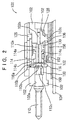
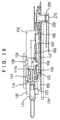
- the winding stem 110 is provided with a square portion 110a and a guide shaft portion 110b.
- a sliding pinion 114 is integrated to the square portion 110a of the winding stem 110.
- the sliding pinion 114 is provided with a rotational axis line the same as a rotational axis line of the winding stem 110. That is, the sliding pinion 114 is provided with a square hole and is provided to rotate based on rotation of the winding stem 110 by fitting the square hole to the corner portion 110a.
- the sliding pinion 114 is provided with an A tooth 114a and a B tooth 114b.
- the A tooth 114a is provided at an end portion of the sliding pinion 114 proximate to the center of the movement.
- the B tooth 114b is provided at an end portion of the sliding pinion remote from the center of the movement.
- a winding pinion 116 is rotatably provided at the guide shaft portion 110b of the winding stem 110.
- the winding pinion 116 is provided with an inner side tooth 116a and an outer side tooth 116b.
- the B tooth 114b of the winding pinion 116 is in mesh with the inner side tooth 116a of the winding pinion 116. Therefore, under the state, it is constituted that when the winding stem 110 is rotated, the winding pinion 116 is rotated via rotation of the sliding pinion 114.
- a setting lever 120 is rotatably arranged on the back side of the main plate 102.
- a yoke 122 is rotatably arranged on the back side of the main plate 102.
- the yoke 122 is urged to press to a front end portion 120a of the setting lever 120 by spring force of a yoke spring portion 122a.
- a yoke holder 124 is provided to press the setting lever 120 and the yoke 122.
- a yoke positioning pin 120b provided at the setting lever 120 is engaged with a yoke positioning ridge portion 124a of the yoke holder 124 and by the yoke holder 124, the setting lever 120 is positioned to three positions in a rotational direction.
- a winding stem guide portion 120c of the setting lever 120 is engaged with a stepped portion 110c of the winding stem 110 and determines a position of the winding stem 110 in a rotational axis line direction based on rotation of the setting lever 120.
- a sliding pinion guide portion 122c of the yoke 122 is engaged with a stepped portion 114c of the sliding pinion 114 and determines a position of the sliding pinion 114 in a rotational axis line direction based on rotation of the yoke 122. Based on rotation of the setting lever 120, the yoke 122 is positioned to two positions in the rotational direction.
- the sliding pinion 114 is disposed at the first position on a side proximate to an outer side of the movement and under the state in which the winding stem 110 is disposed at the "first stage” and the "second stage", the sliding pinion 114 is disposed at the second position proximate to an inner side of the movement.
- the setting lever 120, the yoke 122 and the yoke holder 124 constitute a switch device of the timepiece equipped with a display correction device.
- the setting lever 120 and the yoke positioning ridge portion 124a of the yoke holder 124 constitute winding stem positioning means for positioning a position of the winding stem 110 in the rotational axis line direction.
- the yoke 122 constitutes sliding pinion positioning means operated based on an operation of the setting lever 120 and the yoke holder 124.
- a setting wheel pin 102c constituting the rotational center of a setting wheel is provided on the back side of the main plate 102 and on the rotational axis line of the winding stem 110.
- a setting wheel 128 is rotatably provided to the setting wheel pin 102c.
- the setting wheel 128 is constituted to be not in mesh with the A tooth 114a of the sliding pinion 114 under the state in which the winding stem 110 is disposed at the "0-th stage” and in mesh with the A tooth 114a of the sliding pinion 114 under the state in which the winding stem 110 is disposed at the "first stage” and the "second stage".
- a rocking bar 130 is rockably provided with the setting wheel pin 102c as the rotational center.
- a rocking bar holding frame 136 is fitted to a top portion of the setting wheel pin 102c.
- the rocking bar holding frame 136 is provided to rockably hold the rocking bar 130.
- the rocking bar holding frame 136 may be fixedly attached to the top portion of the setting wheel pin 102c, or, the rocking bar holding frame 136 may be arranged at the top portion of the setting wheel pin 102c.
- the rocking bar 130 includes a rocking bar first portion 130a extended to one side of the setting wheel pin 102c, that is, into the "first region" arranged on the left side of the reference axis line 112 and a rocking bar second portion 130b extended to other side of the setting wheel pin 102c, that is, into the "second region” arranged on the right side of the reference axis line 112.
- the rocking bar 130 is provided with a setting lever engaging portion 130e.
- the setting lever engaging portion 130e of the rocking bar 130 may be constituted as an elastically deformable spring portion.
- a first correction transfer wheel 132 is rotatably attached to the rocking bar first portion 130a.
- a second correction transfer wheel 134 is rotatably attached to the rocking bar first portion 130a.
- the first correction transfer wheel 132 is in mesh with the setting wheel 128 and the second correction transfer wheel 134.
- the first correction transfer wheel 132 is provided with a first correction transfer wheel shaft portion 132a.
- the second correction transfer wheel 134 is provided with a second correction transfer wheel shaft portion 134a.
- a rocking bar positioning hole 102f is provided at the main plate 102.
- the second correction transfer wheel shaft portion 134a is arranged in the rocking bar positioning hole 102f.
- a position in the rotational direction of the rocking bar 130 is determined by bringing the second correction transfer wheel shaft portion 134a in contact with a cylindrical wall face of the rocking bar positioning hole 102f.
- the first correction transfer wheel 132 and the second correction transfer wheel 134 constitute a first corrector train wheel provided at the rocking bar 130 for correcting display content of a date indicator 150 and a day indicator 152 based on the rotation of the setting wheel 128 when the winding stem 110 is disposed at the second winding stem position (first stage).
- a number of the correction transfer wheels constituting the first corrector train wheel is preferably two, the number may be one or may be three or more.
- a third correction transfer wheel 140 is rotatably provided at the main plate 102.
- a rocking lever 142 is rockably provided to the third correction transfer wheel.
- the rocking lever 142 is attached to the third correction transfer wheel 140 such that the third correction transfer wheel 140 can slip against the rocking lever 142 when constant slip torque is exceeded.
- the embodiment of the invention may be constituted such that the slip torque is 1 to 2 g ⁇ cm.
- a corrector setting wheel 144 is rotatably provided to the rocking lever 142.
- the corrector setting wheel 144 is provided with a corrector setting pinion 144a, a corrector setting gear 144b and a corrector setting wheel shaft portion 144c.
- the third correction transfer wheel 140 is in mesh with the second correction transfer wheel 134 and the corrector setting pinion 144a.
- a rocking lever positioning hole 102g is provided at the main plate 102.
- the corrector setting wheel shaft portion 144c is arranged in the rocking lever positioning hole 102g. A position in the rotational direction of the rocking lever 142 is determined by bringing the corrector setting wheel shaft portion 144c in contact with a cylindrical wall face of the rocking lever positioning hole 102g.
- the date indicator 150 constituting a date display member for displaying date is rotatably integrated to the main plate 102.
- the date indicator 150 is provided with 31 of date indicator teeth and is rotated by a date feeding mechanism (not illustrated). A position in the rotational direction of the date indicator 150 is determined by a date jumper (not illustrated).
- a date indicator holder 156 holds the date indicator 150.
- the day indicator 152 constituting a day display member for displaying day of the week is provided.
- the day indicator 152 is provided with a day star wheel 154 having 14 of teeth and the day indicator 152 is rotated by a day feeding mechanism (not illustrated). A position in the rotational direction of the day indicator 152 is determined by a day jumper (not illustrated).
- a day corrector setting wheel 158 is rotatably integrated.
- the day corrector setting wheel 158 is in mesh with the day star wheel 154.
- a first intermediate minute wheel 160 is rotatably attached to the rocking bar second portion 130b.
- a second intermediate minute wheel 162 is rotatably attached to the rocking bar second portion 130b.
- the first intermediate minute wheel 160 is in mesh with the setting wheel 128 and the second intermediate minute wheel 162.
- a minute wheel 166 is arranged at the "second region" on the right side of the reference axis line 112.
- the first intermediate minute wheel 160 and the second intermediate minute wheel 162 constitute a second correction train wheel provided to the rocking bar 130 for correcting the display content of the time display member by rotating the minute wheel 166 based on rotation of the setting wheel 128 when the winding stem 110 is disposed at the third winding stem position (second stage).
- a number of the intermediate minute wheels for constituting the second correction train wheel is preferably two, the number may be one or may be three or more.
- the winding stem 110 is disposed at the 0-th stage and the first stage, by the setting lever 120, the train wheel stop lever 170 is rotated in the clockwise direction and a rocking bar contact portion 170a of the train wheel stop lever 170 is positioned by being brought into contact with the first correction transfer wheel shaft portion 132a.
- the rocking bar 130 By pushing the first correction transfer wheel shaft portion 132a by the train wheel stop lever 170, the rocking bar 130 is rotated in the counterclockwise direction. As described above, the position in the rotational direction of the rocking bar 130 is determined by rotating the rocking bar 130 in the counterclockwise direction and bringing the second correction transfer wheel shaft portion 134a in contact with the cylindrical wall face of the rocking bar positioning hole 102f. Under the state, the train wheel stop lever 170 is not brought into contact with a balance with hairspring 210.
- a rocking crown wheel 222 is rocked while being rotated, in mesh with a ratchet wheel 224 and rotates the ratchet wheel 224 in a constant direction.
- a click 226 is provided to hamper rotation of the ratchet wheel 224 in the reverse direction.
- a movement barrel complete 230 includes a movement barrel complete stem 232, a mainspring 234, a movement barrel complete gear 236 and a movement barrel complete cover 238. Based on rotation of the ratchet wheel, the movement barrel complete stem is rotated and winds up the mainspring 234. By power of the mainspring 234, the movement barrel complete gear 236 is rotated in a constant direction. Based on rotation of the movement barrel complete gear 236, the front train wheel is rotated and a second hand and a minute hand constituting the time display member are rotated. The rotational speed of the front train wheel is controlled by a speed control device including the balance with hairspring 210 and an escapement device.
- the back train wheel including the minute wheel 166 and the hour wheel is rotated to thereby rotate the hour hand. Further, based on rotation of the back train wheel, a date feed mechanism is operated, the date indicator 150 is rotated, a day feed mechanism is operated and the day indicator 152 is rotated.
- the winding stem 110 is drawn by one stage from the state in which the winding stem 110 is disposed at the 0-th stage to the state in which the winding stem 110 is disposed at the first stage.
- the setting lever 120 is rotated in the counterclockwise direction and the yoke 122 is rotated in the clockwise direction.
- the A tooth 122a of the sliding pinion 114 is in mesh with the setting wheel 128 and the B tooth 122b of the sliding pinion 114 is not in mesh with the winding pinion 116.
- the train wheel stop lever 170 When the winding stem 110 is disposed at the first stage, as described above, the train wheel stop lever 170 is rotated in the clockwise direction by the setting lever 170 and the rocking bar contact portion 170a of the train wheel stop lever 170 is positioned by being brought into contact with the first correction transfer wheel shaft portion 132a.
- the rocking bar 130 By the operation of the train wheel stop lever 170, the rocking bar 130 is rotated in the counterclockwise direction and the second correction transfer wheel shaft portion 134a is brought into contact with a cylindrical wall face of the rocking bar positioning hole 102f proximate to the 9 o'clock side. Under the state, the train wheel stop lever 170 is not brought into contact with the balance with hairspring 210.
- the setting wheel 128 is rotated in the counterclockwise direction.
- the first correction transfer wheel 132 is rotated in the clockwise direction.
- the second correction transfer wheel 134 is rotated in the counterclockwise direction.
- the third correction transfer wheel 140 is rotated in the clockwise direction.
- the rocking lever 142 is rotated in the clockwise direction and the corrector setting wheel shaft portion 144c is positioned by being brought into contact with a cylindrical wall face of the rocking lever positioning hole 102g on a side proximate to the 3 o'clock side.
- the third correction transfer wheel 140 can be made to slip against the rocking lever 142.
- the corrector setting wheel 144 is rotated in the counterclockwise direction at a position shown by Fig. 4.
- the date wheel 150 is rotated in the counterclockwise direction.
- the position in the rotational direction of the date indicator 150 is determined by a date jumper 180.
- date correction can be carried out.
- the rocking lever 142 is rotated in the counterclockwise direction and the corrector setting wheel shaft portion 144c is positioned by being brought into contact with the cylindrical wall face at the rocking lever positioning hole 102g on a side proximate to the 9 o'clock side.
- the third correction transfer wheel 140 can be made to slip against the rocking lever 142.
- the corrector setting wheel 144 is rotated in the clockwise direction at a position shown by Fig. 7.
- the day corrector setting wheel 158 is rotated in the counterclockwise direction.
- the day indicator 152 is rotated in the clockwise direction.
- the position in the rotational direction of the day indicator 150 is determined by a day jumper 182.
- day correction can be carried out.
- the date feeding mechanism of the timepiece equipped with the display correction device includes a date indicator driving wheel 252 rotated by one rotation in 24 hours based on rotation of an hour wheel 250 rotated by one rotation in 12 hours and a date indicator driving finger 254.
- the day feed mechanism of the timepiece equipped with the display correction device includes a day indicator driving finger 258 for feeding the date indicator 152 by 2 teeth per day based on rotation of the date indicator driving wheel 252.
- the day indicator 152 is rotatably supported relative to the hour wheel 250 by a day indicator holding spacer 162.
- the winding stem 110 is drawn by further one stage from the first stage to thereby bring about the state in which the winding stem 110 is disposed at the second stage.
- the setting lever 120 is rotated further in the counterclockwise direction. In this operation, the yoke 122 is not rotated. Therefore, in the state in which the winding stem 110 is disposed at the second stage, similar to the state in which the winding stem 110 is disposed at the first stage, the A tooth 122a of the sliding pinion 114 stays to be in mesh with the setting wheel 128 and the B tooth 122b of the sliding pinion 114 is not in mesh with the winding pinion 116.
- the train wheel stop operating portion 170f of the train wheel stop lever 170 may be constituted by an end face of the train wheel stop lever 170 or may be constituted by orthogonally bending the end face of the train wheel stop lever 170 or may be constituted by fixing a separate pin for stopping train wheel at the end portion of the train wheel stop lever 170.
- a setting lever positioning pin 120b pushes the setting lever engaging portion 130e of the rocking bar 130.
- the rocking bar 130 is rotated in the clockwise direction and the second correction transfer wheel shaft portion 134a is brought into contact with the cylindrical wall face of the rocking bar positioning hole 102f on a side proximate to the 3 o'clock side.
- the second intermediate minute wheel 162 is in mesh with the minute wheel 166.
- the winding stem 110 When the winding stem 110 is rotated to the right (when the winding stem 110 is rotated in the clockwise direction in view from the outer side of the timepiece), based on rotation of the sliding pinion 128, the first intermediate minute wheel 160 is rotated in the clockwise direction. Based on rotation of the first intermediate minute wheel 160, the second intermediate minute wheel 162 is rotated in the counterclockwise direction. Based on rotation of the second intermediate minute wheel 162, the minute wheel 166 is rotated in the clockwise direction. Based on rotation of the minute wheel 166, the hour wheel 250 and the minute driving wheel 260 are rotated in the counterclockwise direction. Therefore, when the winding stem 110 is disposed at the second stage, by rotating the winding stem 110 to the right, so-to-speak "inverse hand setting" can be carried out.
- the setting wheel 128 is rotated in the clockwise direction.
- the first intermediate minute wheel 160 is rotated in the counterclockwise direction.
- the second intermediate minute wheel 162 is rotated in the clockwise direction.
- the minute wheel 166 is rotated in the counterclockwise direction.
- the hour wheel 250 and the minute driving wheel 260 are rotated in the clockwise direction. Therefore, when the winding stem 110 is disposed at the second stage, by rotating the winding stem 110 to the left, so-to-speak "regular hand setting" can be carried out.
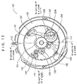
- the date indicator 150 on the back side of the timepiece equipped with the display correction device according to the invention, there are arranged the date indicator 150, the day indicator 152 (including the day star wheel 154) and the switch device (including the setting lever, the yoke and the yoke holder).
- a rotational center 254t of the date indicator driving finger 254 and the day driving finger 258 is arranged at the second region on the right side of the reference axis line 112 of the movement.
- the rotational center 254t of the date indicator driving finger 254 and the day indicator driving finger 258 is arranged at a region of a half of the second region remote from the winding stem 110 (referred to as "6 through 9 o'clock region").
- it is preferable to arrange the rotational center 254t of the date indicator driving finger 254 and the day indicator driving finger 258 is arranged substantially in the "8 o'clock direction" of the movement.
- the date jumper 180 is arranged at the first region on the left side of the reference axis line 112 of the movement.
- the date jumper 180 is arranged at a region of a half of the first region remote from the winding stem 110 (referred to as "9 through 12 o'clock region" in correspondence with numerals of the dial).
- a rotational center 180t of the date jumper 180 substantially between the "10 o'clock direction” and the "11 o'clock direction” of the movement.
- a portion of the date jumper 180 engaged with the date indicator 150 is arranged substantially between the "9 o'clock direction" and the "10 o'clock direction”.
- the day jumper 182 is arranged at the second region on the right side of the reference axis line 112 of the movement.
- the day jumper 182 is arranged at a region of a half of the first region proximate to the winding stem 110 (referred to as "3 through 6 o'clock region” in correspondence with numerals of the dial).
- a portion of the day jumper 182 engaged with the day indicator is arranged substantially between the "6 o'clock direction" and the "7 o'clock direction" of the movement.
- a rotational center 158t of the day correction transfer wheel 158 is arranged at the first region on the left side of the reference axis line 112 of the movement. It is preferable that the rotational center 158t of the day correction transfer wheel 158 is arranged substantially in the "12 o'clock direction" of the movement.
- a rotational center 140t of the third correction transfer wheel 140 is arranged at the first region on the left side of the reference axis line 112 of the movement. It is preferable that the rotational center 150t of the third correction transfer wheel 140 is arranged substantially in the "1 o'clock direction" of the movement.
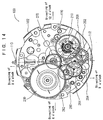
- the movement barrel complete 230 on the front side of the timepiece equipped with the display correction device according to the invention, there are arranged the movement barrel complete 230, a center wheel & pinion 280, a third wheel & pinion 284, the minute driving wheel 270, a minute transmission pinion 282, the second wheel 264, the escape wheel & pinion 262, the pallet fork 268 and the balance with hairspring 210.
- a rotational center of the movement barrel complete 230, a rotational center of the center wheel & pinion 280 and a rotational center of the third wheel & and pinion 284 are arranged on the second region on the left side of the reference axis line 112 of the movement.
- the rotational center of the movement barrel complete 230 is arranged at a region of a half of the second region proximate to the winding stem 110 (referred to as "3 through 6 o'clock region" in correspondence with numerals of the dial). Particularly, it is preferable that the rotational center of the movement barrel complete 230 is arranged between the "5 o'clock direction" and the "6 o'clock direction" of the movement.
- the rotational center of the center wheel & pinion 280 and the rotational center of the third wheel & pinion 284 are arranged at a region of the second region remote from the winding stem 110 (referred to as "6 through 9 o'clock region" in correspondence with numerals of the dial).
- the rotational center of the second wheel 264 is arranged on the reference axis line 112 of the movement at a position remote from the winding stem 110. Particularly, it is preferable that the rotational center of the second wheel 264 is arranged in the "9 o'clock direction" of the movement.
- the structure of the timepiece shown by Fig. 14 constitutes a timepiece having a so-to-speak "small second hand".
- the rotational center of the second hand 266 can be arranged at the center of the movement.
- Such a structure constitutes a timepiece of so-to-speak "central three hands".
- the rotational center of the escape wheel & pinion 262, the rotational center of the pallet fork 268 and the rotational center of the balance with hairspring 210 are arranged at the first region on the right side of the reference axis line 112 of the movement.
- the rotational center of the escape wheel & pinion 162, the rotational center of the pallet fork 268 and the rotational center of the balance with hairspring 210 are arranged at a region of a half of the first region remote from the winding stem 110 (referred to as "9 through 12 o'clock region"). Particularly, it is preferable to arrange the rotational center of the balance with hairspring 210 between the "10 o'clock direction" and the "11 o'clock direction" of the movement.
- the center wheel & pinion 280 is rotated with the mainspring contained in the movement barrel complete 230 as a power source. Based on rotation of the center wheel & pinion 280, the second wheel 264 is rotated via the third wheel & pinion 284. The second hand 266 attached to the second wheel 264 displays "second". The rotational speed of the second wheel 264 is controlled by the balance with hairspring 210, the pallet fork 268 and the escape wheel & pinion 262.
- the minute driving wheel 270 is rotated via the minute transmission pinion 282.
- the minute hand 276 attached to the minute driving wheel 270 displays "minute”.
- the minute driving wheel 270 is provided with a slip mechanism.
- the minute wheel 166 is rotated.
- the hour wheel 250 is rotated.
- the hour hand 256 attached to the hour wheel 250 displays "o'clock".
- the date indicator driving wheel 252 By rotating the date indicator driving pinion 250c provided integrally to the hour wheel 250, the date indicator driving wheel 252 is rotated. By rotating the date indicator driving wheel 252, the date indicator driving finger 254 feeds the date indicator 150 by one tooth per day. By rotating the date indicator driving wheel 252, the day indicator driving finger 258 feeds the day indicator 152 by two teeth per day. Rotation of the date indicator 150 is restrained by the date jumper 180. Rotation of the day indicator 152 is restrained by the day jumper 182.
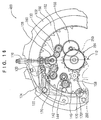
- a movement 400 of a second embodiment of a timepiece equipped with a display correction device according to the invention is constituted by an analog electronic timepiece.
- a point of the movement 400 of the second embodiment of the timepiece equipped with a display correction device according to the invention which differs from the movement 100 of the first embodiment of the timepiece equipped with the display correction device according to the invention, resides in the structure on the front side, that is, constitutions of a power source, a control device for controlling rotational speed of train wheel and front train wheel of the timepiece.
- a switch device, a back train wheel, a hand setting device, a date feed device, a day feed device, a date correction device and a day correction device are similar to those in the structure of the movement 100. Therefore, with regard to Fig. 16, an explanation of portions similar to those in the structure shown by Fig. 1 will be omitted.
- a train wheel stop wheel 292 is arranged on the front side of the movement 400.
- the train wheel stop wheel 292 is in mesh with the second wheel 264 or a fourth wheel & pinion 290.
- the train wheel stop wheel 294 is constituted to be in mesh with the second wheel 264.
- the train wheel stop wheel 292 is constituted to be in mesh with the fourth wheel & pinion 290.
- the train wheel stop lever 170 is constituted to restrain the train wheel stop wheel 292 when the train wheel stop lever 170 is operated.
- the rotational center of the train wheel stop wheel 292 is arranged at a region of a half of the first region of the movement remote from the winding stem 110 (referred to as "9 through 12 o'clock region” in correspondence with numerals of the dial). Particularly, it is preferable that the rotational center of the train wheel stop wheel 292 is arranged between the "10 o'clock direction" and the "11 o'clock direction" of the movement.
- a movement 500 of a third embodiment of a timepiece equipped with a display correction device according to the invention is constituted by an analog electronic timepiece.
- a point of the movement 500 of the third embodiment of the timepiece equipped with a display correction apparatus according to the invention which differs from the movement 400 of the second embodiment of the timepiece equipped with the display correction device according to the invention, resides in that arrangement of parts on the front side and arrangement of parts on the back side are arranged in symmetry (mirror symmetry) with regard to the reference axis line 112.
- the rotational center of the train wheel stop wheel 292 is arranged at a region of a half of the second region of the movement remote from the winding stem 110 (referred to as "6 through 9 o'clock region" in correspondence with numerals of the dial). Particularly, it is preferable that the rotational center of the train wheel stop wheel 292 is arranged between the "7 o'clock direction" and the "8 o'clock direction" of the movement.
- a timepiece equipped with a display correction device according to the invention is constituted by a mechanical type timepiece
- parts shown by Fig. 12 through Fig. 14 can be arranged in left and right symmetry (mirror symmetry) with regard to the reference axis line 112.
- the movement 400 of the timepiece equipped with the display correction device according to the invention is not provided with a winding pinion and a winding device.
- the winding stem 110 is disposed at the 0-th stage, there is no gear in mesh with the sliding pinion 114. It is not necessary to provide a B tooth to the sliding pinion 114.
- Operation in the state in which the winding stem 110 is disposed at the first stage is similar to operation of the first embodiment of the timepiece equipped with the display correction device according to the invention.
- the train wheel stop lever 170 By rotating the setting lever 120, the train wheel stop lever 170 is rotated in the counterclockwise direction and the train wheel stop operating portion 170f of the train wheel stop lever 170 is brought into contact with the train wheel stop wheel 292 and stops rotation of the train wheel stop wheel 292. As a result, rotation of the fourth wheel & pinion 290 in mesh with the train wheel stop wheel 292 is restrained and rotation of the second hand 266 is stopped.
- a gear restrained by the train wheel stop lever 170 may be the train wheel stop wheel 292 in mesh with the fourth wheel & pinion 290 or may be the fourth wheel & pinion 290. Further, as shown by Fig. 19, in the case of a timepiece in which the fourth wheel & pinion 290 and a fifth wheel & pinion 170 are provided and the second wheel 266 is attached to the fourth wheel & pinion 290, the fourth wheel & pinion 290 may be restrained or the fifth wheel & pinion 170 may be restrained.
- operation of the rocking bar 130 by rotation of the setting lever 120 and operation of the setting wheel 128, the first intermediate minute wheel 160 and the second intermediate minute wheel 162 by rotation of the winding stem 110 are similar to those of the operation of the first embodiment of the timepiece equipped with the display correction device according to the invention.
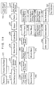
- the second embodiment and the third embodiment of the timepiece equipped with the display correction device according to the invention are electric timepieces, for example, analog electric timepieces each having the display correction device.
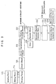
- a battery 420 constitutes a power source of the timepiece and a crystal oscillator 422 is oscillated at, for example, 32,768 Hertz.
- an oscillating circuit 424 Based on the oscillation of the crystal oscillator 422, an oscillating circuit 424 outputs a reference signal and a dividing circuit 426 divides an output signal of the oscillating circuit 424.
- a drive circuit 428 Based on the output signal of the dividing circuit 426, a drive circuit 428 outputs a motor drive signal for driving a step motor.
- a stator 432 is magnetized to thereby rotate a rotor 434.
- the rotor 434 is rotated by, for example, 180 degree per second.
- the fourth wheel & pinion 290 is rotated via rotation of the fifth wheel & pinion 440.
- the fourth wheel & pinion 290 is constituted to rotate by one rotation per minute.
- the second hand 266 is attached to the fourth wheel & pinion 290.
- the second wheel may be constituted to rotate via one or more train wheel based on rotation of the rotor 434.
- the fourth wheel & pinion 290 or the second wheel may be arranged at the center of the timepiece or may be arranged at a position different from the center of the timepiece.
- the third wheel & pinion 284 is rotated based on rotation of the fourth wheel & pinion 290.
- the center wheel & pinion 280 is rotated based on rotation of the third wheel & pinion 284.
- a minute driving wheel may be used in place of the center wheel & pinion 280.
- the minute hand 276 is attached to the center wheel & pinion 280.
- the slip mechanism is provided to the center wheel & pinion 280 or the minute driving wheel. When hand setting is carried out by the slip mechanism, in the state in which the second hand 266 is stationary, by rotating the winding stem 110, the minute hand 276 and the hour hand 256 can be rotated.
- the center wheel & pinion 280 or the minute driving wheel is rotated once per hour.
- the minute wheel 166 is rotated based on rotation of the center wheel & pinion 280.
- the hour wheel 250 is rotated based on rotation of the minute wheel 166.
- the hour wheel 250 is rotated once per 12 hours.
- the date indicator driving wheel 252 By rotating the date indicator driving pinion 250c of the hour wheel 250, the date indicator driving wheel 252 is rotated and the date indicator driving finger 254 feeds the date indicator 150 by one tooth per day.
- the day indicator driving finger 258 feeds the day indicator 152 by 2 teeth per day. Rotation of the date indicator 150 is restrained by the date jumper 180. Rotation of the day wheel 152 is restrained by the day jumper 182.
- the number of teeth of the day start wheel may be 7 or may be 21.
- the day indicator driving finger 258 is constituted to feed the day indicator 152 by 3 teeth per day.
- the structure of the display correction device according to the invention is applicable also to a "two hands timepiece” or a "one hand timepiece” having no second hand.
- display members capable of being corrected when the winding stem 110 is disposed at the first stage are the date indicator 150 and the day indicator 152
- the structure of the display correction device according to the invention is applicable also to a timepiece having only the date indicator 150.
- a plurality of display members to which the structure of the display correction device according to the invention is applicable may be, for example, a month indicator, a moon phase indicator, a six day indicator, a year indicator and so on.
- the invention is constituted as described above in the timepiece equipped with the display correction device and accordingly, there are achieved effects described below.
Landscapes
- Physics & Mathematics (AREA)
- General Physics & Mathematics (AREA)
- Electromechanical Clocks (AREA)
Abstract
Description
upper direction and upper side of the wrist watch are respectively referred to as "direction of 12 o'clock" and "side of 12 o'clock",
right direction and right side of the wrist watch are respectively referred to as "direction of 3 o'clock" and "side of 3 o'clock",
lower direction and lower side of the wrist watch are respectively referred to as "direction of 6 o'clock" and "side of 6 o'clock",
left direction and left side of the wrist watch are respectively referred to as "direction of 9 o'clock" and "side of 9 o'clock".
directions in correspondence with from 1 o'clock scale to 11 o'clock scale are respectively referred to as from "direction of 1 o'clock" to "direction of 11 o'clock" and positions in correspondence with from 1 o'clock scale to 11 o'clock scale of the
Claims (21)
- A timepiece equipped with a display correction device which is a timepiece equipped with a display correction device capable of correcting a display content by rotation of a winding stem, characterized in comprising:a first information display member (150) for displaying first information;a second information display member (256, 276) for displaying second information;a winding stem (110) having a rotational axis line for correcting a display content of the first information display member (150) and correcting a display content of the second information display member (256, 276);a sliding pinion (114) having a rotational axis line the same as the rotational axis line of the winding stem (110) and provided to rotate based on rotation of the winding stem (110);winding stem positioning means (120, 124) for positioning the winding stem (110) at a first winding stem position in a direction of the rotational axis line, a second winding stem position in the direction of the rotational axis line and a third winding stem position in the direction of the rotational axis line;sliding pinion positioning means (122) for positioning the sliding pinion (114) at a first sliding pinion position in the direction of the rotational axis line when the winding stem (110) is disposed at the first winding stem position and positioning the sliding pinion (114) at a second sliding pinion position in the direction of the rotational axis line when the winding stem (110) is disposed at the second winding stem position and the third winding stem position based on movement of the winding stem (110) in the direction of the rotational axis line;a rocking bar (130) having a rotational center on the rotational axis line of the winding stem (110) and provided to rock in a first rotational direction when the winding stem (110) is disposed at the second winding stem position and rock in a second rotational direction different from the first rotational direction when the winding stem (110) is disposed at the third position;first corrector setting means (132, 134) provided to the rocking bar (130) for correcting the display content of the first information display member (150) based on rotation of the sliding pinion (114) when the winding stem (110) is disposed at the second winding stem position; andsecond corrector setting means (160, 162) for correcting the display content of the second information display member (256, 276) based on the rotation of the sliding pinion (114) when the winding stem (110) is disposed at the third winding stem position.
- The timepiece equipped with a display correction device according to Claim 1, characterized in further comprising a setting wheel (128) having a rotational center disposed at a position the same as a position of the rotational center of the rocking bar (130) and provided to rotate based on the rotation of the sliding pinion (114) when the winding stem (110) is disposed at the second winding stem position and the third winding stem position.
- The timepiece equipped with a display correction device according to Claim 1 or Claim 2, characterized in that the first corrector setting means includes one or more of correction transfer wheel (132, 134, 140) provided to rotate based on the rotation of the setting wheel (128) and a corrector setting wheel (144) provided to rotate based on rotation of the correction transfer wheel (132, 134) for correcting the display content of the first information display member (150).
- The timepiece equipped with a display correction device according to Claim 3, characterized in further comprising a rocking lever (142) provided to rock based on the rotation of the correction transfer wheel (140) when the winding stem (110) is disposed at the second winding stem position and the corrector setting wheel (144) is rotatably attached to the rocking lever (142).
- The timepiece equipped with a display correction device according to Claim 4, characterized in further comprising rocking lever positioning means (102g, 144c) for restraining a position in a rotational direction of the rocking lever (142).
- The timepiece equipped with a display correction device according to any one of Claim 1 through Claim 5, characterized in further comprising rocking bar positioning means (102f, 134a) for restraining a position in a rotational direction of the rocking bar (130).
- The timepiece equipped with a display correction device according to any one of Claim 1 through Claim 6, characterized in that rotation of the rocking bar (130) is determined based on operation of the winding stem positioning means (120).
- The timepiece equipped with a display correction device according to any one of Claim 1 through Claim 7, characterized in further providing a train wheel stop lever (170) provided to operate based on the operation of the winding stem positioning means (120) for restraining operation of the second information display member (256, 276) when the winding stem (110) is disposed at the third winding stem position.
- The timepiece equipped with a display correction device according to Claim 8, characterized in that rotation of the rocking bar (130) is determined based on the operation of the winding stem positioning means (170) when the winding stem (110) is disposed at the third winding stem position.
- The timepiece equipped with a display correction device according to any one of Claim 4 through Claim 9, characterized in further comprising a third information display member (152) for displaying third information:
wherein when the winding stem (110) is disposed at the second winding stem position, in the case in which the winding stem (110) is rotated in a first winding stem rotating direction, the rocking lever (142) is rotated in a first rocking lever rotating direction and the corrector setting wheel (144) corrects the first information display member (150); and
wherein when the winding stem (110) is disposed at the second winding stem position, in the case in which the winding stem (110) is rotated in a second winding stem rotating direction different from the first winding stem rotating direction, the rocking lever (142) is rotated in a second rocking lever rotating direction different from the first rocking lever rotating direction and the corrector setting wheel (144) corrects the third information display member (152). - The timepiece equipped with a display correction device according to any one of Claim 1 through Claim 10, characterized in that the second correcting means includes one or more of intermediate minute wheel (160, 162) provided to rotate based on rotation of the setting wheel (128) and including a minute wheel (166) provided to rotate based on rotation of the intermediate minute wheel (160, 162) when the winding stem (110) is disposed at the third winding stem position.
- The timepiece equipped with a display correction device according to Claim 8 or Claim 9, characterized in that the timepiece is constituted by a mechanical type timepiece having a balance with hairspring (210) and when the winding stem (110) is disposed at the third winding stem position, the train wheel stop lever (170) restrains the balance with hairspring (210).
- The timepiece equipped with a display correction device according to Claim 8 or Claim 9, characterized in that the timepiece includes a front train wheel for displaying second and when the winding stem (110) is disposed at the third winding stem position, the train wheel stop lever (170) restrains one gear (292, 290, 440) in the front train wheel.
- A timepiece equipped with a display correction device which is a timepiece equipped with a display correction device capable of correcting a display content by rotation of a winding stem, characterized in comprising:a time display member (256, 276) for displaying time;a date display member (150) for displaying date;a day display member (152) for displaying day;a winding stem (110) having a rotational axis line for correcting a display content of the time display member (256, 276), the date display member (150) and the day display member (152);a sliding pinion (114) having a rotational axis line the same as the rotational axis line of the winding stem (110) and rotated based on the rotation of the winding stem (110);a switch device (120, 122, 124) for positioning the winding stem (110) at a first winding stem position in a direction of the rotational axis line, a second winding stem position in the direction of the rotational axis line and a third winding stem position in the direction of the rotational axis line, positioning the sliding pinion (114) at a first sliding pinion position in the direction of the rotational axis line when the winding stem (110) is disposed at the first winding stem position and positioning the sliding pinion (114) at a second sliding pinion position in the direction of the rotational axis line when the winding stem (110) is disposed at the second winding stem position and the third winding stem position based on movement of the winding stem (110) in the direction of the rotational axis line;a rocking bar (130) having a rotational center on the rotational axis line of the winding stem (110) and provided to rock in a first rotational direction when the winding stem (110) is disposed at the second winding stem position and rock in a second rotational direction different from the first rotational direction when the winding stem (110) is disposed at the third position;a setting wheel (128) having a rotational center at a position the same as a position of the rotational center of the rocking bar (130) and provided to rotate based on rotation of the sliding pinion (114) when the winding stem (110) is disposed at the second winding stem position and the third winding stem position;a first corrector setting train wheel (132, 134) provided to the rocking bar (130) for correcting the display content of the date display member (150) and the day display member (152) based on rotation of the setting wheel (128) when the winding stem (110) is disposed at the second winding stem position; anda second corrector setting train wheel (160, 162) provided to the rocking bar (130) for correcting the display content of the time display member (256, 276) based on the rotation of the setting wheel (128) when the winding stem (110) is disposed at the third winding stem position.
- The timepiece equipped with a display correction device according to Claim 14, characterized in that the first corrector setting train wheel includes one or more of correction transfer wheel (132, 134) provided to rotate based on the rotation of the setting wheel (128);
wherein the timepiece further includes:a rocking lever (142) provided to rock based on rotation of the correction transfer wheel (132, 134) when the winding stem (110) is disposed at the second winding stem position; anda corrector setting wheel (144) attached to the rocking lever (142) to rotate based on the rotation of the correction transfer wheel when the winding stem (110) is disposed at the second winding stem position;
wherein when the winding stem (110) is disposed at the second winding stem position, in the case in which the winding stem (110) is rotated in a first winding stem rotating direction, the rocking lever (142) is rotated in a first rocking lever direction and the corrector setting wheel (144) corrects the date display member (150); and
wherein when the winding stem (110) is disposed at the second hand setting position, in the case in which the winding stem (110) is rotated in a second winding stem rotating direction different from the first winding stem rotating direction, the rocking lever (142) is rotated in a second rocking lever rotating direction different from the first rocking lever rotating direction and the corrector setting wheel (144) corrects the day display member (152). - The timepiece equipped with a display correction device according to Claim 14 or Claim 15, characterized in that the second corrector setting train wheel includes one or more of intermediate minute wheel (160, 162) provided to rotate based on rotation of the setting wheel (128) and including a minute wheel (166) provided to rotate based on rotation of the intermediate minute wheel (160, 162) via rotation of the intermediate minute wheel (160, 162) when the winding stem (110) is disposed at the third winding stem position.
- The timepiece equipped with a display correction device according to any one of Claim 14 through Claim 16, characterized in further comprising a train wheel stop lever (170) operated based on operation of the switch device (120, 122, 124) for restraining operation of the time display member (256, 276) when the time setting stem (110) is disposed at the third winding stem position.
- A timepiece equipped with a display correction device which is a timepiece equipped with a display correction device capable of correcting a display content by rotation of a winding stem, characterized in comprising:a time display member (256, 276) for displaying time;a date display member (150) for displaying date;a day display member (152) for displaying day;a winding stem (110) having a rotational axis line for correcting a display content of the time display member (256, 276), the date display member (150) and the day display member (152);a sliding pinion (114) having a rotational axis line the same as the rotational axis line of the winding stem (110) and rotated based on the rotation of the winding stem (110);a switch device (120, 122, 124) for positioning the winding stem (110) at a first winding stem position in a direction of the rotational axis line, a second winding stem position in the direction of the rotational axis line and a third winding stem position in the direction of the rotational axis line, positioning the sliding pinion (114) at a first sliding pinion position in the direction of the rotational axis line when the winding stem (110) is disposed at the first winding stem position and positioning the sliding pinion (114) at a second sliding pinion position in the direction of the rotational axis line when the winding stem (110) is disposed at the second winding stem position and the third winding stem position based on movement of the winding stem (110) in the direction of the rotational axis line;a rocking bar (130) having a rotational center on the rotational axis line of the winding stem (110) and provided to rock in a first rotational direction when the winding stem (110) is disposed at the second winding stem position and rock in a second rotational direction different from the first rotational direction when the winding stem (110) is disposed at the third position;a setting wheel (128) having a rotational center at a position the same as a position of the rotational center of the rocking bar (130) and provided to rotate based on rotation of the sliding pinion (114) when the winding stem (110) is disposed at the second winding stem position and the third winding stem position;a first corrector setting train wheel (132, 134) provided to the rocking bar (130) for correcting the display content of the date display member (150) and the day display member (152) based on rotation of the setting wheel (128) when the winding stem (110) is disposed at the second winding stem position; anda second corrector setting train wheel (160, 162) provided to the rocking bar (130) for correcting the display content of the time display member based on the rotation of the setting wheel (128) when the winding stem (110) is disposed at the third winding stem position;
wherein the first corrector setting train wheel is arranged at a first region on one side of a reference axis line when the rotational axis line of the winding stem (110) is made to constitute the reference axis line of the timepiece; and
wherein the second corrector setting train wheel is arranged at a second region on other side of the reference axis line. - The timepiece equipped with a display correction device according to Claim 18, characterized in that the first corrector setting train wheel includes one or more of correction transfer wheel (132, 134) provided to rotate based on the rotation of the setting wheel (128);
wherein the timepiece further includes:a rocking lever (142) provided to rock based on rotation of the correction transfer wheel (132, 134) when the winding stem (110) is disposed at the second winding stem position; anda corrector setting wheel (144) attached to the rocking lever (142) to rotate based on the rotation of the correction transfer wheel when the winding stem (110) is disposed at the second winding stem position;
wherein when the winding stem (110) is disposed at the second winding stem position, in the case in which the winding stem (110) is rotated in a first winding stem rotating direction the rocking lever (142) is rotated in a first rocking lever direction and the corrector setting wheel (144) corrects the date display member (152); and
wherein when the winding stem (110) is disposed at the second hand setting position, in the case in which the winding stem (110) is rotated in a second winding stem rotating direction different from the first winding stem rotating direction, the rocking lever (142) is rotated in a second rocking lever rotating direction different from the first rocking lever rotating direction and the corrector setting wheel (144) corrects the day display member (152); and
wherein the second corrector setting train wheel includes one or more of intermediate minute wheel (160, 162) provided to rotate based on rotation of the setting wheel (128), further comprising:a minute wheel (166) provided at the second region relative to the reference axis line to rotate based on rotation of the second corrector setting train wheel via the intermediate minute wheel (160, 162) when the winding stem (110) is disposed at the third winding stem position. - The timepiece equipped with a display correction device according to Claim 18 or Claim 19, characterized in further comprising a train wheel stop lever (170) provided in the first region relative to the reference axis line and operated based on operation of the switch device for restraining operation of the time display member when the winding stem (110) is disposed at the third winding stem position.
- A correction device for a timepiece which is a correction device for a timepiece for correcting a display content based on rotation of a winding stem, characterized in comprising:a gear for corrector setting (128) having a rotational center which is not moved relative to a movement of the timepiece and rotatably fixed to the movement to be rotatable based on the rotation of the winding stem (110);a rocking bar (130) having a rotational center on an axis line the same as an axis line of the rotational center of the gear for corrector setting (128), including a first portion (130a) extended in a first direction from the rotational center and a second portion (130b) extended in a second direction from the rotational center, rockable in a first rotational direction relative to the movement and rockable in a second rotational direction different from the first rotational direction;at least one first correction transfer wheel (132, 134) provided at the first portion (130a) of the rocking bar (130) to rotate based on rotation of the gear for corrector setting (128); andat least one second correction transfer wheel (160, 162) provided at the second portion (130b) of the rocking bar (130) to rotate based on the rotation of the gear for corrector setting (128).
Applications Claiming Priority (3)
| Application Number | Priority Date | Filing Date | Title |
|---|---|---|---|
| JP9357352A JPH11183649A (en) | 1997-12-25 | 1997-12-25 | Clock with display correction device |
| JP35735297 | 1997-12-25 | ||
| PCT/JP1998/005940 WO1999034262A1 (en) | 1997-12-25 | 1998-12-24 | Timepiece equipped with display correction device |
Publications (2)
| Publication Number | Publication Date |
|---|---|
| EP1043634A1 true EP1043634A1 (en) | 2000-10-11 |
| EP1043634A4 EP1043634A4 (en) | 2001-03-21 |
Family
ID=18453695
Family Applications (1)
| Application Number | Title | Priority Date | Filing Date |
|---|---|---|---|
| EP98961584A Withdrawn EP1043634A4 (en) | 1997-12-25 | 1998-12-24 | WATCH WITH DISPLAY CORRECTION DEVICE |
Country Status (6)
| Country | Link |
|---|---|
| US (1) | US6295249B1 (en) |
| EP (1) | EP1043634A4 (en) |
| JP (1) | JPH11183649A (en) |
| CN (1) | CN1285053A (en) |
| TW (1) | TW392096B (en) |
| WO (1) | WO1999034262A1 (en) |
Cited By (4)
| Publication number | Priority date | Publication date | Assignee | Title |
|---|---|---|---|---|
| CN1049208C (en) * | 1994-08-10 | 2000-02-09 | 中国石油化工总公司 | Method for preparing 1,4-butanediol |
| WO2018172093A1 (en) * | 2017-03-22 | 2018-09-27 | Sa De La Manufacture D'horlogerie Audemars Piguet & Cie | Device for adjusting functions of a timepiece |
| EP3584644A1 (en) | 2018-06-20 | 2019-12-25 | Patek Philippe SA Genève | Winding mechanism and rocker correction for clock movement |
| WO2024046724A1 (en) | 2022-08-29 | 2024-03-07 | Richemont International Sa | Bidirectional correction device and timepiece movement comprising such a device |
Families Citing this family (26)
| Publication number | Priority date | Publication date | Assignee | Title |
|---|---|---|---|---|
| US6711099B1 (en) * | 2001-04-10 | 2004-03-23 | Watch-U-License Ag | Setting and winding mechanism |
| DE10160287A1 (en) * | 2001-12-07 | 2003-06-26 | Lange Uhren Gmbh | Tourbillon |
| JP4149751B2 (en) * | 2002-06-27 | 2008-09-17 | セイコーインスツル株式会社 | Electronic watch with reset lever with bush |
| JP2004170271A (en) * | 2002-11-20 | 2004-06-17 | Seiko Instruments Inc | Clock with calendar |
| JP4296018B2 (en) * | 2003-03-27 | 2009-07-15 | セイコーインスツル株式会社 | Chronograph watch with calendar mechanism |
| JP4462606B2 (en) * | 2004-01-27 | 2010-05-12 | セイコーインスツル株式会社 | Clock with display correction mechanism |
| DE602006001298D1 (en) * | 2006-05-31 | 2008-07-03 | Montres Breguet Sa | Clock comprising an improved time setting device |
| ATE460690T1 (en) * | 2007-01-30 | 2010-03-15 | Longines Montres Comp D | CLOCK COMPRISING A DRIVING MECHANISM OF A DEVICE FOR DISPLAYING A QUANTITY RELATED TO TIME |
| ATE475117T1 (en) * | 2007-04-04 | 2010-08-15 | Eta Sa Mft Horlogere Suisse | ELEVATOR DEVICE WITH UNIDIRECTIONAL CLUTCH |
| ATE487962T1 (en) * | 2007-04-04 | 2010-11-15 | Eta Sa Mft Horlogere Suisse | GEAR FOR A CLOCK MOVEMENT AND DEVICE FOR CORRECTING A DISPLAY MECHANISM FOR A WATCH HAVING SUCH A GEAR |
| JP5343670B2 (en) * | 2009-04-01 | 2013-11-13 | セイコーエプソン株式会社 | clock |
| EP3339967B1 (en) * | 2011-06-21 | 2025-02-12 | Rolex Sa | Timepiece including a correction mechanism of at least two display elements |
| EP2565728B1 (en) * | 2011-08-29 | 2018-05-09 | ETA SA Manufacture Horlogère Suisse | Independent control mechanism for a timepiece |
| CN103869681B (en) * | 2012-12-12 | 2016-03-02 | 天王电子(深圳)有限公司 | The upper bar handsetting mechanism of a kind of mechanical watch and mechanical watch |
| CH707870B1 (en) * | 2013-04-08 | 2017-07-14 | Gfpi S A | Mechanism for selecting and operating the functions of a watch movement and a timepiece comprising such a mechanism. |
| US9519273B2 (en) * | 2014-03-06 | 2016-12-13 | Seiko Epson Corporation | Electronic timepiece and movement |
| EP2945026B1 (en) * | 2014-05-14 | 2018-01-03 | ETA SA Manufacture Horlogère Suisse | Quick correction mechanism of a timepiece |
| EP2945024B1 (en) * | 2014-05-14 | 2017-07-12 | ETA SA Manufacture Horlogère Suisse | Timepiece lever |
| JP6492928B2 (en) * | 2015-04-22 | 2019-04-03 | セイコーエプソン株式会社 | Timepiece and timepiece manufacturing method |
| EP3333642B1 (en) * | 2016-12-06 | 2019-08-21 | ETA SA Manufacture Horlogère Suisse | Clockwork mechanism for bi-directional correction of a plurality of displays |
| CH714741B1 (en) * | 2018-03-12 | 2022-06-30 | Hublot Sa Geneve | Locking system for a watch barrel ratchet. |
| CN110209041B (en) * | 2019-05-31 | 2021-02-12 | 福建瑞达精工股份有限公司 | Method for quickly calibrating alarm starting point of clock |
| JP6751215B1 (en) * | 2020-03-02 | 2020-09-02 | セイコーウオッチ株式会社 | Balance wheel setting mechanism, clock movement and clock |
| EP4220308B1 (en) * | 2020-11-27 | 2025-12-24 | Omega SA | Jumping timepiece display mechanism with rollers |
| CH718513A1 (en) * | 2021-04-07 | 2022-10-14 | Mft Dhorlogerie Audemars Piguet Sa | Device for selecting and actuating several functions of a watch movement. |
| CN118624723B (en) * | 2024-08-12 | 2024-11-29 | 西安石油大学 | Ultrasonic detection device for natural gas pipeline defects |
Family Cites Families (15)
| Publication number | Priority date | Publication date | Assignee | Title |
|---|---|---|---|---|
| JPS372249B1 (en) * | 1958-10-31 | 1962-05-19 | ||
| US3114237A (en) * | 1961-02-23 | 1963-12-17 | Movado Montres | Winding system actuated by a rocking bar |
| JPS4216609Y1 (en) * | 1964-10-30 | 1967-09-25 | ||
| JPS4322941Y1 (en) * | 1965-06-08 | 1968-09-27 | ||
| JPS4833335Y1 (en) * | 1969-08-07 | 1973-10-09 | ||
| JPS4833336A (en) | 1971-09-03 | 1973-05-09 | ||
| JPS4881868U (en) * | 1971-12-29 | 1973-10-05 | ||
| BE794271A (en) * | 1972-01-21 | 1973-05-16 | Timex Corp | WATCH MOVEMENT WITH HAND ADJUSTMENT AND BALANCER STOPPING DEVICE |
| JPS4881868A (en) | 1972-02-15 | 1973-11-01 | ||
| US3797226A (en) * | 1972-05-16 | 1974-03-19 | Citizen Watch Co Ltd | Timepiece fitted with a regulator controllable from outside |
| JPS5410263B2 (en) * | 1973-03-31 | 1979-05-02 | ||
| DE2442950A1 (en) * | 1974-09-07 | 1976-03-18 | Timex Corp | HAND SETTING DEVICE FOR CLOCKS |
| CH1468974A4 (en) * | 1974-11-01 | 1976-04-30 | ||
| JPS5381059A (en) | 1976-12-27 | 1978-07-18 | Toshiba Corp | Digital phase synchronizing system |
| CH640686B (en) * | 1980-10-23 | Ebauchesfabrik Eta Ag | SLIDING CONTROL DEVICE FOR WATCH. |
-
1997
- 1997-12-25 JP JP9357352A patent/JPH11183649A/en active Pending
-
1998
- 1998-12-24 EP EP98961584A patent/EP1043634A4/en not_active Withdrawn
- 1998-12-24 TW TW087121647A patent/TW392096B/en active
- 1998-12-24 US US09/582,016 patent/US6295249B1/en not_active Expired - Lifetime
- 1998-12-24 CN CN98813630A patent/CN1285053A/en active Pending
- 1998-12-24 WO PCT/JP1998/005940 patent/WO1999034262A1/en not_active Ceased
Cited By (5)
| Publication number | Priority date | Publication date | Assignee | Title |
|---|---|---|---|---|
| CN1049208C (en) * | 1994-08-10 | 2000-02-09 | 中国石油化工总公司 | Method for preparing 1,4-butanediol |
| WO2018172093A1 (en) * | 2017-03-22 | 2018-09-27 | Sa De La Manufacture D'horlogerie Audemars Piguet & Cie | Device for adjusting functions of a timepiece |
| US11550267B2 (en) | 2017-03-22 | 2023-01-10 | Manufacture D'horlogerie Audemars Piguet Sa | Device for adjusting the functions of a timepiece |
| EP3584644A1 (en) | 2018-06-20 | 2019-12-25 | Patek Philippe SA Genève | Winding mechanism and rocker correction for clock movement |
| WO2024046724A1 (en) | 2022-08-29 | 2024-03-07 | Richemont International Sa | Bidirectional correction device and timepiece movement comprising such a device |
Also Published As
| Publication number | Publication date |
|---|---|
| CN1285053A (en) | 2001-02-21 |
| WO1999034262A1 (en) | 1999-07-08 |
| US6295249B1 (en) | 2001-09-25 |
| JPH11183649A (en) | 1999-07-09 |
| EP1043634A4 (en) | 2001-03-21 |
| TW392096B (en) | 2000-06-01 |
Similar Documents
| Publication | Publication Date | Title |
|---|---|---|
| US6295249B1 (en) | Display correction device and timepiece equipped with display correction device | |
| US8264912B2 (en) | Watch with calendar mechanism having two date indicators | |
| EP0851321B1 (en) | Multi-functional timepiece | |
| US7492669B2 (en) | Timepiece attached with calendar mechanism having first date indicator and second date indicator | |
| JP5382720B2 (en) | A watch with a calendar mechanism including the 1st day wheel and the 2nd day wheel | |
| US7102962B2 (en) | Timepiece equipped with calendar mechanism including first and second date indicators | |
| US7215602B2 (en) | Multifunction timepiece capable of constituting plural fan shape moving hand train wheel layouts | |
| US6406176B1 (en) | Chronograph timepiece | |
| US6428201B1 (en) | Chronograph timepiece and lever device for timepiece | |
| JP5181133B2 (en) | A clock with a calendar mechanism equipped with a month wheel and a date wheel | |
| JP3081991B2 (en) | Self-winding wristwatch | |
| US6814483B2 (en) | Self-winding timepiece having train wheel setting apparatus | |
| US20050162983A1 (en) | Timepiece having display correcting mechanism | |
| EP1898277B1 (en) | Multi-function timepiece capable of realizing a plurality of movement layouts | |
| US7106661B2 (en) | Calendar timepiece | |
| US7532546B2 (en) | Timepiece with calendar mechanism having date indicators for indicating date | |
| US20070097794A1 (en) | Timepiece with a fan-shaped hand motion display mechanism | |
| US20070047390A1 (en) | Timepiece with calendar mechanism indicating date by plurality of date indicators | |
| JP2006170762A (en) | Multi-function timepiece with fan-shaped wheel train and fan-shaped wheel train | |
| JP7560390B2 (en) | Information display mechanism, movement and clock | |
| CN102169323A (en) | Timekeeper with calendar mechanism | |
| US20060193208A1 (en) | Timepiece with small hand indicating mechanism | |
| HK1025398B (en) | Multi-functional timepiece | |
| HK1116551B (en) | Multi-function timepiece including a plurality of types of hand-moving wheel trains |
Legal Events
| Date | Code | Title | Description |
|---|---|---|---|
| PUAI | Public reference made under article 153(3) epc to a published international application that has entered the european phase |
Free format text: ORIGINAL CODE: 0009012 |
|
| 17P | Request for examination filed |
Effective date: 20000623 |
|
| AK | Designated contracting states |
Kind code of ref document: A1 Designated state(s): CH DE FR GB LI |
|
| A4 | Supplementary search report drawn up and despatched |
Effective date: 20010206 |
|
| AK | Designated contracting states |
Kind code of ref document: A4 Designated state(s): CH DE FR GB LI |
|
| 17Q | First examination report despatched |
Effective date: 20040901 |
|
| STAA | Information on the status of an ep patent application or granted ep patent |
Free format text: STATUS: THE APPLICATION IS DEEMED TO BE WITHDRAWN |
|
| 18D | Application deemed to be withdrawn |
Effective date: 20050112 |