EP1043292A1 - Cutting tool and method of manufacturing the same - Google Patents
Cutting tool and method of manufacturing the same Download PDFInfo
- Publication number
- EP1043292A1 EP1043292A1 EP00302841A EP00302841A EP1043292A1 EP 1043292 A1 EP1043292 A1 EP 1043292A1 EP 00302841 A EP00302841 A EP 00302841A EP 00302841 A EP00302841 A EP 00302841A EP 1043292 A1 EP1043292 A1 EP 1043292A1
- Authority
- EP
- European Patent Office
- Prior art keywords
- cutting tool
- phase
- cutting
- sintering
- silicon nitride
- Prior art date
- Legal status (The legal status is an assumption and is not a legal conclusion. Google has not performed a legal analysis and makes no representation as to the accuracy of the status listed.)
- Withdrawn
Links
- 238000005520 cutting process Methods 0.000 title claims abstract description 92
- 238000004519 manufacturing process Methods 0.000 title claims abstract description 12
- 229910052581 Si3N4 Inorganic materials 0.000 claims abstract description 48
- HQVNEWCFYHHQES-UHFFFAOYSA-N silicon nitride Chemical compound N12[Si]34N5[Si]62N3[Si]51N64 HQVNEWCFYHHQES-UHFFFAOYSA-N 0.000 claims abstract description 46
- 239000013078 crystal Substances 0.000 claims abstract description 32
- NRTOMJZYCJJWKI-UHFFFAOYSA-N Titanium nitride Chemical compound [Ti]#N NRTOMJZYCJJWKI-UHFFFAOYSA-N 0.000 claims abstract description 29
- 238000002441 X-ray diffraction Methods 0.000 claims abstract description 16
- 239000011159 matrix material Substances 0.000 claims abstract description 16
- PNEYBMLMFCGWSK-UHFFFAOYSA-N aluminium oxide Inorganic materials [O-2].[O-2].[O-2].[Al+3].[Al+3] PNEYBMLMFCGWSK-UHFFFAOYSA-N 0.000 claims abstract description 15
- 238000000034 method Methods 0.000 claims abstract description 14
- RUDFQVOCFDJEEF-UHFFFAOYSA-N yttrium(III) oxide Inorganic materials [O-2].[O-2].[O-2].[Y+3].[Y+3] RUDFQVOCFDJEEF-UHFFFAOYSA-N 0.000 claims abstract description 13
- 239000011521 glass Substances 0.000 claims abstract description 8
- 238000005245 sintering Methods 0.000 claims description 49
- 239000012299 nitrogen atmosphere Substances 0.000 claims description 15
- 229910045601 alloy Inorganic materials 0.000 claims description 14
- 239000000956 alloy Substances 0.000 claims description 14
- 239000012298 atmosphere Substances 0.000 claims description 4
- IJGRMHOSHXDMSA-UHFFFAOYSA-N Atomic nitrogen Chemical compound N#N IJGRMHOSHXDMSA-UHFFFAOYSA-N 0.000 claims 1
- 229910001873 dinitrogen Inorganic materials 0.000 claims 1
- 238000001513 hot isostatic pressing Methods 0.000 claims 1
- 239000000463 material Substances 0.000 description 14
- 239000000203 mixture Substances 0.000 description 9
- 230000000052 comparative effect Effects 0.000 description 7
- 239000007789 gas Substances 0.000 description 7
- LFQSCWFLJHTTHZ-UHFFFAOYSA-N Ethanol Chemical compound CCO LFQSCWFLJHTTHZ-UHFFFAOYSA-N 0.000 description 4
- 238000002425 crystallisation Methods 0.000 description 4
- 230000008025 crystallization Effects 0.000 description 4
- 230000001771 impaired effect Effects 0.000 description 4
- 238000002474 experimental method Methods 0.000 description 3
- 239000000843 powder Substances 0.000 description 3
- 229910001018 Cast iron Inorganic materials 0.000 description 2
- 230000003247 decreasing effect Effects 0.000 description 2
- 230000006735 deficit Effects 0.000 description 2
- 238000011156 evaluation Methods 0.000 description 2
- 229910001026 inconel Inorganic materials 0.000 description 2
- 238000003754 machining Methods 0.000 description 2
- 230000000704 physical effect Effects 0.000 description 2
- 239000002002 slurry Substances 0.000 description 2
- 229910001247 waspaloy Inorganic materials 0.000 description 2
- ATJFFYVFTNAWJD-UHFFFAOYSA-N Tin Chemical compound [Sn] ATJFFYVFTNAWJD-UHFFFAOYSA-N 0.000 description 1
- RTAQQCXQSZGOHL-UHFFFAOYSA-N Titanium Chemical compound [Ti] RTAQQCXQSZGOHL-UHFFFAOYSA-N 0.000 description 1
- 239000011230 binding agent Substances 0.000 description 1
- 230000015572 biosynthetic process Effects 0.000 description 1
- 238000010276 construction Methods 0.000 description 1
- 238000001816 cooling Methods 0.000 description 1
- 229910052593 corundum Inorganic materials 0.000 description 1
- 230000007423 decrease Effects 0.000 description 1
- 230000000694 effects Effects 0.000 description 1
- 230000001747 exhibiting effect Effects 0.000 description 1
- 238000000227 grinding Methods 0.000 description 1
- 238000007731 hot pressing Methods 0.000 description 1
- 229910000816 inconels 718 Inorganic materials 0.000 description 1
- 238000007373 indentation Methods 0.000 description 1
- XEEYBQQBJWHFJM-UHFFFAOYSA-N iron Substances [Fe] XEEYBQQBJWHFJM-UHFFFAOYSA-N 0.000 description 1
- 238000002844 melting Methods 0.000 description 1
- 230000008018 melting Effects 0.000 description 1
- 229910052751 metal Inorganic materials 0.000 description 1
- 239000002184 metal Substances 0.000 description 1
- 239000004200 microcrystalline wax Substances 0.000 description 1
- 229940114937 microcrystalline wax Drugs 0.000 description 1
- 235000019808 microcrystalline wax Nutrition 0.000 description 1
- 238000002156 mixing Methods 0.000 description 1
- 229910052759 nickel Inorganic materials 0.000 description 1
- 238000005498 polishing Methods 0.000 description 1
- 238000010298 pulverizing process Methods 0.000 description 1
- 239000011369 resultant mixture Substances 0.000 description 1
- 239000002904 solvent Substances 0.000 description 1
- 239000000126 substance Substances 0.000 description 1
- 230000001629 suppression Effects 0.000 description 1
- MZLGASXMSKOWSE-UHFFFAOYSA-N tantalum nitride Chemical compound [Ta]#N MZLGASXMSKOWSE-UHFFFAOYSA-N 0.000 description 1
- 239000010936 titanium Substances 0.000 description 1
- 229910052719 titanium Inorganic materials 0.000 description 1
- XLYOFNOQVPJJNP-UHFFFAOYSA-N water Substances O XLYOFNOQVPJJNP-UHFFFAOYSA-N 0.000 description 1
- 229910001845 yogo sapphire Inorganic materials 0.000 description 1
Images


Classifications
-
- B—PERFORMING OPERATIONS; TRANSPORTING
- B23—MACHINE TOOLS; METAL-WORKING NOT OTHERWISE PROVIDED FOR
- B23B—TURNING; BORING
- B23B27/00—Tools for turning or boring machines; Tools of a similar kind in general; Accessories therefor
- B23B27/14—Cutting tools of which the bits or tips or cutting inserts are of special material
-
- C—CHEMISTRY; METALLURGY
- C04—CEMENTS; CONCRETE; ARTIFICIAL STONE; CERAMICS; REFRACTORIES
- C04B—LIME, MAGNESIA; SLAG; CEMENTS; COMPOSITIONS THEREOF, e.g. MORTARS, CONCRETE OR LIKE BUILDING MATERIALS; ARTIFICIAL STONE; CERAMICS; REFRACTORIES; TREATMENT OF NATURAL STONE
- C04B35/00—Shaped ceramic products characterised by their composition; Ceramics compositions; Processing powders of inorganic compounds preparatory to the manufacturing of ceramic products
- C04B35/515—Shaped ceramic products characterised by their composition; Ceramics compositions; Processing powders of inorganic compounds preparatory to the manufacturing of ceramic products based on non-oxide ceramics
- C04B35/58—Shaped ceramic products characterised by their composition; Ceramics compositions; Processing powders of inorganic compounds preparatory to the manufacturing of ceramic products based on non-oxide ceramics based on borides, nitrides, i.e. nitrides, oxynitrides, carbonitrides or oxycarbonitrides or silicides
- C04B35/584—Shaped ceramic products characterised by their composition; Ceramics compositions; Processing powders of inorganic compounds preparatory to the manufacturing of ceramic products based on non-oxide ceramics based on borides, nitrides, i.e. nitrides, oxynitrides, carbonitrides or oxycarbonitrides or silicides based on silicon nitride
- C04B35/593—Shaped ceramic products characterised by their composition; Ceramics compositions; Processing powders of inorganic compounds preparatory to the manufacturing of ceramic products based on non-oxide ceramics based on borides, nitrides, i.e. nitrides, oxynitrides, carbonitrides or oxycarbonitrides or silicides based on silicon nitride obtained by pressure sintering
-
- C—CHEMISTRY; METALLURGY
- C04—CEMENTS; CONCRETE; ARTIFICIAL STONE; CERAMICS; REFRACTORIES
- C04B—LIME, MAGNESIA; SLAG; CEMENTS; COMPOSITIONS THEREOF, e.g. MORTARS, CONCRETE OR LIKE BUILDING MATERIALS; ARTIFICIAL STONE; CERAMICS; REFRACTORIES; TREATMENT OF NATURAL STONE
- C04B35/00—Shaped ceramic products characterised by their composition; Ceramics compositions; Processing powders of inorganic compounds preparatory to the manufacturing of ceramic products
- C04B35/515—Shaped ceramic products characterised by their composition; Ceramics compositions; Processing powders of inorganic compounds preparatory to the manufacturing of ceramic products based on non-oxide ceramics
- C04B35/58—Shaped ceramic products characterised by their composition; Ceramics compositions; Processing powders of inorganic compounds preparatory to the manufacturing of ceramic products based on non-oxide ceramics based on borides, nitrides, i.e. nitrides, oxynitrides, carbonitrides or oxycarbonitrides or silicides
- C04B35/584—Shaped ceramic products characterised by their composition; Ceramics compositions; Processing powders of inorganic compounds preparatory to the manufacturing of ceramic products based on non-oxide ceramics based on borides, nitrides, i.e. nitrides, oxynitrides, carbonitrides or oxycarbonitrides or silicides based on silicon nitride
-
- C—CHEMISTRY; METALLURGY
- C04—CEMENTS; CONCRETE; ARTIFICIAL STONE; CERAMICS; REFRACTORIES
- C04B—LIME, MAGNESIA; SLAG; CEMENTS; COMPOSITIONS THEREOF, e.g. MORTARS, CONCRETE OR LIKE BUILDING MATERIALS; ARTIFICIAL STONE; CERAMICS; REFRACTORIES; TREATMENT OF NATURAL STONE
- C04B35/00—Shaped ceramic products characterised by their composition; Ceramics compositions; Processing powders of inorganic compounds preparatory to the manufacturing of ceramic products
- C04B35/515—Shaped ceramic products characterised by their composition; Ceramics compositions; Processing powders of inorganic compounds preparatory to the manufacturing of ceramic products based on non-oxide ceramics
- C04B35/58—Shaped ceramic products characterised by their composition; Ceramics compositions; Processing powders of inorganic compounds preparatory to the manufacturing of ceramic products based on non-oxide ceramics based on borides, nitrides, i.e. nitrides, oxynitrides, carbonitrides or oxycarbonitrides or silicides
- C04B35/584—Shaped ceramic products characterised by their composition; Ceramics compositions; Processing powders of inorganic compounds preparatory to the manufacturing of ceramic products based on non-oxide ceramics based on borides, nitrides, i.e. nitrides, oxynitrides, carbonitrides or oxycarbonitrides or silicides based on silicon nitride
- C04B35/593—Shaped ceramic products characterised by their composition; Ceramics compositions; Processing powders of inorganic compounds preparatory to the manufacturing of ceramic products based on non-oxide ceramics based on borides, nitrides, i.e. nitrides, oxynitrides, carbonitrides or oxycarbonitrides or silicides based on silicon nitride obtained by pressure sintering
- C04B35/5935—Shaped ceramic products characterised by their composition; Ceramics compositions; Processing powders of inorganic compounds preparatory to the manufacturing of ceramic products based on non-oxide ceramics based on borides, nitrides, i.e. nitrides, oxynitrides, carbonitrides or oxycarbonitrides or silicides based on silicon nitride obtained by pressure sintering obtained by gas pressure sintering
Definitions
- the present invention relates to a cutting tool which contains silicon nitride as matrix and to a method of manufacturing the cutting tool.
- Japanese Patent Publication ( kokoku ) No. 60-48475 proposes a silicon-nitride-based sintered body which is manufactured through hot-pressing and contains one or more components selected from the group consisting of titanium nitride and tantalum nitride.
- Japanese Patent Application Laid-Open ( kokai ) No. 9-268071 discloses a silicon-nitride tool which mainly contains silicon nitride and titanium carbonitride.
- a silicon-nitride tool of this kind is used for machining (cutting) parts made of cast iron.
- the above-mentioned silicon-nitride tool is used for cutting not only cast iron but also a super heat-resisting alloy. Since a super heat-resisting alloy exhibits poor thermal conductivity, heat tends to accumulate at the cutting edge of the tool.
- cutting with such a tool has involved a problem in that, as cutting-edge temperature rises, softening of a grain boundary phase (which, together with a matrix phase and a hard phase, constitutes the microstructure of the tool) advances, with a resultant impairment in wear resistance of the tool.
- the present invention addresses the above-mentioned problem, and an object of the present invention is to provide a cutting tool having excellent wear resistance, etc. as well as to provide a method of manufacturing the tool.
- the invention provides:
- Titanium nitride 10%-20% by weight
- Titanium nitride exhibits high wear resistance against a molten metal. Accordingly, when the titanium nitride content of a cutting tool material is less than 10% by weight, wear resistance is not improved sufficiently. When the titanium nitride content is in excess of 20% by weight, sintering properties tend to be impaired. Thus, titanium nitride is contained most preferably in an amount of 10% to 20% by weight.
- Alumina 3%-5% by weight
- alumina content of the cutting tool material is less than 3% by weight, sintering properties are impaired.
- alumina content is in excess of 5% by weight, hardness decreases, with a resultant impairment in wear resistance.
- alumina is contained most preferably in an amount of 3% to 5% by weight.
- yttria content of the cutting tool material is less than 5% by weight, sintering properties are impaired.
- the yttria content is in excess of 15% by weight, the crystal phase increases.
- yttria is contained most preferably in an amount of 5%-15% by weight.
- the silicon nitride content in % by weight is balanced with the total amount in % by weight of titanium nitride, alumina, and yttria.
- a portion of the grain boundary phase is crystallized to assume the crystal phase, so that the amount of the glass phase in the grain boundary phase is decreased.
- the peak-to-peak ratio R is less than 0.05, the amount of the crystal phase becomes too small, causing impaired suppression of softening of the grain boundary phase and thus impairing wear resistance.
- the peak-to-peak ratio R is in excess of 0.6, the amount of the crystal phase becomes too large, thus impairing toughness.
- the peak-to-peak ratio R is most preferably not less than 0.05 and not greater than 0.6.
- the present invention specifies composition with respect to four components, microstructure with respect to four phases, and the peak-to-peak ratio R to thereby provide a cutting tool having excellent wear resistance and toughness.
- the crystal phase contains a J phase.
- the J phase i.e., Y 8 Si 4 N 4 O 14
- the glass phase in the grain boundary phase is decreased, so that crystals having high melting point are provided, thereby suppressing softening of the grain boundary phase at high temperature.
- the cutting tool is used for cutting a super heat-resisting alloy.
- This feature exemplifies an application of the cutting tool.
- a super heat-resisting alloy denotes an alloy capable of withstanding use at high temperature not lower than 650°C; specifically, an alloy which contains Fe in an amount of not greater than 50% by weight or an alloy for high-temperature use which contains Ni or Co as a main component.
- a super heat-resisting alloy include an Ni-based alloy, such as Inconel or Waspalloy.
- the cutting tool of the present invention is a particularly preferred tool for cutting the above-mentioned Ni-based alloy (Inconel or Waspalloy).
- Preferred cutting conditions are as follows:
- a cutting edge is located between a rake face and a flank of the cutting tool.
- This feature exemplifies the shape of the cutting tool.
- An example shape of the cutting tool having the cutting edge located between the rake face and the flank is a rectangular parallelepiped.
- Other examples include a quadrangular prism in which the rake face assumes a rhombus shape, a triangular prism in which the rake face assumes a triangular shape, or a circular cylinder in which the rake face assumes a circular shape.
- a method for manufacturing a cutting tool as described above, characterized in that sintering is performed under atmospheric pressure in a nitrogen atmosphere.
- This aspect of the present invention exemplifies a method for manufacturing the cutting tool.
- a material prepared such that the cutting tool assumes the above-mentioned composition and microstructure undergoes forming and then sintering under atmospheric pressure in a nitrogen atmosphere, to thereby yield a silicon-nitride-based sintered body.
- the sintered body undergoes post-machining, such as polishing, to become a cutting tool.
- the cutting tool can be manufactured at lower cost.
- the composition of material for the sintered body (accordingly, the composition of the cutting tool) must be selected appropriately.
- the material is desirably selected such that the cutting tool contains, for example, TiN in an amount of not greater than 10% by weight, a sintering aid in an amount of not less than 6% by weight, and Si 3 N 4 as balance.
- sintering is performed under gas pressure in a nitrogen atmosphere.
- sintering is performed under gas pressure in a nitrogen atmosphere as secondary sintering, thereby providing a sufficiently dense sintered body (for example, equal to or greater than 98% of the theoretical density ratio).
- Sintering under gas pressure is performed under the following conditions: nitrogen atmosphere; desirable pressure of nitrogen atmosphere 5-100 atmospheres; desirable sintering temperature 1600-1800°C.
- sintering is performed by means of HIP (Hot Isostatic Press).
- sintering is performed by means of HIP as secondary sintering, thereby providing a sufficiently dense sintered body (for example, a theoretical density ratio becomes not less than 95%).
- Sintering by means of HIP is performed under the following conditions: nitrogen atmosphere; desirable pressure of nitrogen atmosphere 1000-2000 atmospheres; desirable sintering temperature 1500-1800°C.
- a cutting tool which is formed from a silicon-nitride-based sintered body and is used for cutting a super heat-resisting alloy, and a method for manufacturing the cutting tool will next be described by way of example.
- the density of each sintered body was measured by the Archimedian method. On the basis of the measured density, the theoretical density ratio of the sintered body was obtained.
- each sintered body was mirror-polished.
- the polished surface was observed through a microscope of 200 magnifications to thereby measure micropore according to CIS-006B Standard.
- a ground surface of each sintered body was mirror-polished.
- a Vickers' indenter was pressed against the polished surface under a load of 30 kg. The diagonal length of the resulting indentation and the length of crack were measured to thereby obtain Vickers hardness (according to JIS R1610) and fracture toughness (according to JIS R1607 (IF method)).
- a polished surface of each sintered body was subjected to X-ray diffraction to thereby obtain the peak-to-peak ratio R of the sintered body.
- FIG. 3 is a graph showing the X-ray diffraction result.
- strength [cps] is read along the axis of ordinate, and 2 ⁇ [°] is read along the axis of abscissa.
- the peak-to-peak ratio R is 0.48.
- Peaks obtained through the above-mentioned X-ray diffraction were compared with those of known materials to thereby identify crystal phases.
- each of the cutting tools was fed in the direction of arrow A so as to cut the outer circumferential surface of a rotating cylindrical workpiece under the conditions listed below.
- the cutting edge of the cutting tool was examined for state of wear (amount of wear of flank after 1-pass cutting) and chipping. The result is shown below in Table 1.
- the symbol “1 ⁇ ” indicates sintering under atmospheric pressure; the symbol “2 ⁇ ” indicates sintering under gas pressure; the symbol “3 ⁇ ” indicates HIP; and the symbol “+” indicates that both primary sintering and secondary sintering are performed.
- sintering sample No. 7 quick cooling was performed; and in sintering sample No. 8, the sample was heat-treated through application of heat of 1400°C for 12 hours in a nitrogen atmosphere of 1 atmosphere.
- the symbol “A2” indicates that the amount of micropores is 0.02% by volume; and the symbol “A8” indicates that the amount of micropores is 0.6% by volume.
- sample Nos. 1 to 4 which are examples of the present invention, which contain titanium nitride in an amount as specified in the invention, and which exhibit a peak-to-peak ratio R as specified in the invention ⁇ exhibit excellent wear resistance. Sample Nos. 1 to 4 also exhibit appropriate hardness and toughness, and were free from chipping during experiment.
- example No. 5 serving as a comparative example
- the amount of wear increases.
- example No. 6 serving as a comparative example
- the cutting tool becomes too hard and thus becomes brittle; as a result, the cutting edge chips.
- the cutting tool of the present invention contains the four components of appropriate proportions and assumes a microstructure which exhibits an appropriate combination of the four phases as well as an appropriate peak-to-peak ratio R.
- R peak-to-peak ratio
- the method for manufacturing a cutting tool according to the present invention enables a cutting tool to be eadily manufactured having the above-mentioned excellent performance at low cost.
Landscapes
- Engineering & Computer Science (AREA)
- Chemical & Material Sciences (AREA)
- Ceramic Engineering (AREA)
- Manufacturing & Machinery (AREA)
- Materials Engineering (AREA)
- Structural Engineering (AREA)
- Organic Chemistry (AREA)
- Mechanical Engineering (AREA)
- Ceramic Products (AREA)
- Cutting Tools, Boring Holders, And Turrets (AREA)
Abstract
A cutting tool having excellent wear resistance, etc. and a method for
manufacturing the same are disclosed.
A cutting tool contains silicon nitride as matrix, 10%-20% by weight titanium
nitride, 3%-5% by weight alumina, and 5%-15% by weight yttria. A microstructure
of the cutting tool comprises a matrix phase of silicon nitride, a hard phase of
titanium nitride, a glass phase present in a grain boundary phase, and a crystal phase
present in the grain boundary phase. The ratio R of a maximum peak B of the crystal
phase other than silicon nitride and titanium nitride as observed through X-ray
diffraction to a maximum peak A of silicon nitride as observed through X-ray
diffraction (= B/A) is not less than 0.05 and not greater than 0.6.
Description
- The present invention relates to a cutting tool which contains silicon nitride as matrix and to a method of manufacturing the cutting tool.
- Conventionally, many sintered bodies which contain silicon nitride as matrix (base material) have been developed. For example, Japanese Patent Publication (kokoku) No. 60-48475 proposes a silicon-nitride-based sintered body which is manufactured through hot-pressing and contains one or more components selected from the group consisting of titanium nitride and tantalum nitride.
- Also, Japanese Patent Application Laid-Open (kokai) No. 9-268071 discloses a silicon-nitride tool which mainly contains silicon nitride and titanium carbonitride. A silicon-nitride tool of this kind is used for machining (cutting) parts made of cast iron.
- The above-mentioned silicon-nitride tool is used for cutting not only cast iron but also a super heat-resisting alloy. Since a super heat-resisting alloy exhibits poor thermal conductivity, heat tends to accumulate at the cutting edge of the tool.
- Specifically, cutting with such a tool has involved a problem in that, as cutting-edge temperature rises, softening of a grain boundary phase (which, together with a matrix phase and a hard phase, constitutes the microstructure of the tool) advances, with a resultant impairment in wear resistance of the tool.
- The present invention addresses the above-mentioned problem, and an object of the present invention is to provide a cutting tool having excellent wear resistance, etc. as well as to provide a method of manufacturing the tool.
- Accordingly, the invention provides:
- a cutting tool containing silicon nitride as matrix, 10%-20% by weight titanium nitride, 3%-5% by weight alumina, and 5%-15% by weight yttria. The cutting tool is characterized in that a microstructure thereof comprises a matrix phase of silicon nitride, a hard phase of titanium nitride, a glass phase present in a grain boundary phase, and a crystal phase present in the grain boundary phase, and in that the ratio R of a maximum peak B of the crystal phase other than silicon nitride and titanium nitride as observed through X-ray diffraction to a maximum peak A of silicon nitride as observed through X-ray diffraction (= B/A) is not less than 0.05 and not greater than 0.6.
- 1 ○ The cuffing tool of the present invention is a silicon-nitride-based sintered body which contains silicon nitride as matrix (main component or base material). In addition to silicon nitride, 10%-20% by weight titanium nitride,3%-5% by weight alumina, and 5%-15% by weight yttria are contained. Particularly, silicon nitride serving as matrix is combined with titanium nitride, which features excellent thermal conductivity and low coefficient of friction, thereby improving wear resistance.
-
- The reason for numerical limitation of the components will next be described.
- Titanium nitride exhibits high wear resistance against a molten metal. Accordingly, when the titanium nitride content of a cutting tool material is less than 10% by weight, wear resistance is not improved sufficiently. When the titanium nitride content is in excess of 20% by weight, sintering properties tend to be impaired. Thus, titanium nitride is contained most preferably in an amount of 10% to 20% by weight.
- When the alumina content of the cutting tool material is less than 3% by weight, sintering properties are impaired. When the alumina content is in excess of 5% by weight, hardness decreases, with a resultant impairment in wear resistance. Thus, alumina is contained most preferably in an amount of 3% to 5% by weight.
- When the yttria content of the cutting tool material is less than 5% by weight, sintering properties are impaired. When the yttria content is in excess of 15% by weight, the crystal phase increases. Thus, yttria is contained most preferably in an amount of 5%-15% by weight.
- When the cutting tool is substantially formed from only silicon nitride, titanium nitride, alumina, and yttria, the silicon nitride content in % by weight is balanced with the total amount in % by weight of titanium nitride, alumina, and yttria.
- 2 ○ According to the present invention, in addition to specification of the above-mentioned composition, the microstructure of the cutting tool comprises four phases; namely, a matrix phase (base material phase) of silicon nitride, a hard phase of titanium nitride, a glass phase present in a grain boundary phase, and a crystal phase present in the grain boundary phase. A state of the four phases is schematically shown in FIG. 1. The grain boundary phase is present between the matrix phase and the hard phase and comprises the glass phase and the crystal phase.
-
- According to the present invention, a portion of the grain boundary phase is crystallized to assume the crystal phase, so that the amount of the glass phase in the grain boundary phase is decreased. Thus, even when the cutting-edge temperature rises, softening of the grain boundary phase is reduced; accordingly, wear resistance is improved.
- 3 ○ According to the present invention, the ratio R of a maximum peak B of the crystal phase other than silicon nitride and titanium nitride as observed through X-ray diffraction to a maximum peak A of silicon nitride as observed through X-ray diffraction (= B/A) is not less than 0.05 and not greater than 0.6. Notably, peaks as observed through X-ray diffraction of the crystal phase indicate amounts of known crystals, such as Y8Si4N4O14, Y10Al2Si3O18N4, and Y10Si7N4O23, and unknown crystals contained in the crystal phase.
-
- When the peak-to-peak ratio R is less than 0.05, the amount of the crystal phase becomes too small, causing impaired suppression of softening of the grain boundary phase and thus impairing wear resistance. When the peak-to-peak ratio R is in excess of 0.6, the amount of the crystal phase becomes too large, thus impairing toughness. Thus, the peak-to-peak ratio R is most preferably not less than 0.05 and not greater than 0.6.
- As mentioned above, the present invention specifies composition with respect to four components, microstructure with respect to four phases, and the peak-to-peak ratio R to thereby provide a cutting tool having excellent wear resistance and toughness.
- Preferably the crystal phase contains a J phase.
- This preferred feature exemplifies the construction of the crystal phase. Specifically, the J phase; i.e., Y8Si4N4O14, is contained as a crystal phase. Thus, the glass phase in the grain boundary phase is decreased, so that crystals having high melting point are provided, thereby suppressing softening of the grain boundary phase at high temperature.
- Preferably the cutting tool is used for cutting a super heat-resisting alloy.
- This feature exemplifies an application of the cutting tool.
- Since a super heat-resisting alloy exhibits poor thermal conductivity, heat tends to accumulate at the cutting edge of a tool. However, since the cutting tool of the present invention assumes the above-mentioned microstructure, even when the cutting-edge temperature rises during cutting of a super heat-resisting alloy, softening of the grain boundary phase is suppressed, thereby exhibiting excellent wear resistance.
- Notably, a super heat-resisting alloy denotes an alloy capable of withstanding use at high temperature not lower than 650°C; specifically, an alloy which contains Fe in an amount of not greater than 50% by weight or an alloy for high-temperature use which contains Ni or Co as a main component. Examples of such a super heat-resisting alloy include an Ni-based alloy, such as Inconel or Waspalloy.
- The cutting tool of the present invention is a particularly preferred tool for cutting the above-mentioned Ni-based alloy (Inconel or Waspalloy). Preferred cutting conditions are as follows:
- Cutting speed: V = 100-500 m/min
(more preferably 200-400 m/min) - Feed: f = 0.05-0.4 mm/rev
(more preferably 0.1-0.3 mm/rev) - Depth of cut: d = not less than 0.05 mm
(more preferably not less than 0.1 mm) -
- Preferably a cutting edge is located between a rake face and a flank of the cutting tool.
- This feature exemplifies the shape of the cutting tool. An example shape of the cutting tool having the cutting edge located between the rake face and the flank is a rectangular parallelepiped. Other examples include a quadrangular prism in which the rake face assumes a rhombus shape, a triangular prism in which the rake face assumes a triangular shape, or a circular cylinder in which the rake face assumes a circular shape.
- According to another aspect of the invention there is provided a method for manufacturing a cutting tool, as described above, characterized in that sintering is performed under atmospheric pressure in a nitrogen atmosphere.
- This aspect of the present invention exemplifies a method for manufacturing the cutting tool. A material prepared such that the cutting tool assumes the above-mentioned composition and microstructure undergoes forming and then sintering under atmospheric pressure in a nitrogen atmosphere, to thereby yield a silicon-nitride-based sintered body. Subsequently, the sintered body undergoes post-machining, such as polishing, to become a cutting tool.
- As compared to, for example, HIP, sintering under atmospheric pressure is easier to perform and less expensive. Thus, the cutting tool can be manufactured at lower cost.
- When a silicon-nitride-based sintered body suited for formation of the cutting tool is to be manufactured merely through sintering under atmospheric pressure, the composition of material for the sintered body (accordingly, the composition of the cutting tool) must be selected appropriately. Specifically, the material is desirably selected such that the cutting tool contains, for example, TiN in an amount of not greater than 10% by weight, a sintering aid in an amount of not less than 6% by weight, and Si3N4 as balance.
- Preferably, after the sintering under atmospheric pressure is performed, sintering is performed under gas pressure in a nitrogen atmosphere.
- Unless a special composition is employed, mere sintering under atmospheric pressure (primary sintering) encounters difficulty in providing a sintered body which is sufficiently dense for application to a cutting tool (for example, not greater than 95% of the theoretical density ratio). According to the present invention, sintering is performed under gas pressure in a nitrogen atmosphere as secondary sintering, thereby providing a sufficiently dense sintered body (for example, equal to or greater than 98% of the theoretical density ratio).
- Through combination of sintering under atmospheric pressure and sintering under gas pressure, a sufficiently dense sintered body can be manufactured at low cost.
- Sintering under gas pressure is performed under the following conditions: nitrogen atmosphere; desirable pressure of nitrogen atmosphere 5-100 atmospheres; desirable sintering temperature 1600-1800°C.
- Preferably after the sintering under atmospheric pressure is performed, sintering is performed by means of HIP (Hot Isostatic Press).
- As mentioned above, mere sintering under atmospheric pressure (primary sintering) encounters difficulty in providing a sintered body which is sufficiently dense for application to a cutting tool. According to the present invention, sintering is performed by means of HIP as secondary sintering, thereby providing a sufficiently dense sintered body (for example, a theoretical density ratio becomes not less than 95%).
- Through combination of sintering under atmospheric pressure and sintering by means of HIP, a sufficiently dense sintered body can be manufactured.
- Sintering by means of HIP is performed under the following conditions: nitrogen atmosphere; desirable pressure of nitrogen atmosphere 1000-2000 atmospheres; desirable sintering temperature 1500-1800°C.
- Embodiments of the invention will now be described, by way of example only, with reference to the accompanying drawings, in which:
- Fig. 1 is an explanatory view schematically showing a state of phases constituting a microstructure of a cutting tool;
- Fig. 2 is a perspective view showing the shape of a cutting tool according to an embodiment of the present invention;
- Fig. 3 is a graph showing peaks as observed through X-ray diffraction; and
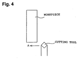
- Fig. 4 is a view showing a method for evaluating cutting performance.
-
- A cutting tool which is formed from a silicon-nitride-based sintered body and is used for cutting a super heat-resisting alloy, and a method for manufacturing the cutting tool will next be described by way of example.
- a) First, the cutting tool of the present embodiment will be described. As shown in FIG. 2, a cutting tool 1 of the present embodiment is a negative tip which assumes an SNGN120408 shape according to ISO Standard.Specifically, as shown in FIG. 2, the cutting tool 1 includes upper and lower rake faces 3, four flanks 5 at sides, and cutting edges 7, each of which is a side edge located between the rake face 3 and the flank 5. The cutting tool 1 is a rectangular-parallelepiped tip having a thickness of 4.76 mm and the cutting edges 7 of a 12.7 mm length. The cutting edges 7 are chamfered.The cutting tool 1 of the present embodiment is formed from a silicon-nitride-based sintered body, which contains silicon nitride as matrix (base material). Specifically, the cutting tool 1 contains 10%-20% by weight titanium nitride, 3%-5% by weight alumina, 5%-15% by weight yttria, and silicon nitride as balance.Further, the microstructure of the cutting tool 1 includes a matrix phase of silicon nitride, a hard phase of titanium nitride, a glass phase present in a grain boundary phase, and a crystal phase present in the grain boundary phase. Also, the ratio R of a maximum peak B of the crystal phase other than silicon nitride and titanium nitride as observed through X-ray diffraction to a maximum peak A of silicon nitride as observed through X-ray diffraction (= B/A) is not less than 0.05 and not greater than 0.6.
- b) Next, a method for manufacturing the cutting tool 1 of the present embodiment will be described. Measure out silicon nitride (Si3N4) powder, which is a main component, having an average grain size of 0.5 µm (α percentage = not less than 99%), yttria (Y2O3) powder having an average grain size of 0.8 µm, and alumina (Al2O3) powder having an average grain size of 0.4 µm, according to the composition (in the "examples of the present invention" column) shown in Table 1 so as to establish the composition of the cutting tool 1.The thus-measured materials, together with alumina balls, are placed in a pot lined with alumina and are subjected to wet mixing and pulverization in an ethanol solvent for 16 hours, thereby yielding slurry.This slurry is dried in hot water. To the resulting substance, a microcrystalline-wax-based organic binder (3.5% by weight) dissolved in ethanol is added. The resultant mixture is mixed in a ball mill.The thus-obtained basis material is press-formed to an SNGN120408 shape according to ISO Standard, followed by dewaxing through application of heat of 800°C for 60 minutes in a nitrogen atmosphere maintained at 1 atmosphere.Next, primary sintering is performed through application of heat of 1700°C for 4 hours in a nitrogen atmosphere maintained at atmospheric pressure (1 atmosphere).Next, sintering under gas pressure is performed as secondary sintering through application of heat of 1750°C for 4 hours in a nitrogen atmosphere maintained at 75 atmospheres.Instead of sintering under gas pressure, sintering by means of HIP may be performed as secondary sintering. Secondary sintering by means of HIP is performed through application of heat of 1700°C for 4 hours in a nitrogen atmosphere maintained at 1000 atmospheres.The thus-obtained silicon-nitride-based sintered body is heat-treated in a nitrogen atmosphere under the conditions (in the "examples of the present invention" column) shown below in Table 1 so as to accelerate crystallization of the grain boundary phase. The thus-heat-treated silicon-nitride-based sintered body undergoes grinding so as to be formed into an SNGN120408 shape according to ISO Standard, whereby the cutting tool 1 is completed.
- c) Next will be described experiments which were conducted in order to confirm the effects of cutting tools conforming to the ranges as specified in the present invention. Cutting tools were manufactured under the conditions shown below in Table 1 as samples for use in the experiments. Sample Nos. 1 to 4 represent examples of the present invention, and sample Nos. 5 to 10 represent comparative examples. The manufactured cutting-tool samples assumed an SNGN120408 shape according to ISO Standard.The cutting-tool sample Nos. 1 to 10 were evaluated for physical properties as described below in (i) and for cutting performance as described below in (ii).
-
- Sintered bodies were examined for density, micropore, hardness, toughens, peak-to-peak ratio R (amount of crystal phase), and crystals in crystal phase. The results are shown below in Table 1.
- The density of each sintered body was measured by the Archimedian method. On the basis of the measured density, the theoretical density ratio of the sintered body was obtained.
- The cross section of each sintered body was mirror-polished. The polished surface was observed through a microscope of 200 magnifications to thereby measure micropore according to CIS-006B Standard.
- A ground surface of each sintered body was mirror-polished. A Vickers' indenter was pressed against the polished surface under a load of 30 kg. The diagonal length of the resulting indentation and the length of crack were measured to thereby obtain Vickers hardness (according to JIS R1610) and fracture toughness (according to JIS R1607 (IF method)).
- A polished surface of each sintered body was subjected to X-ray diffraction to thereby obtain the peak-to-peak ratio R of the sintered body. For example, when the X-ray diffraction result as shown in FIG. 3 is obtained, the maximum peak height A of silicon nitride (= I (Si3N4max)) and the maximum peak height B of the crystal phase other than silicon nitride and titanium nitride (= I (GBmax)) are measured. The peak-to-peak ratio R (=
- FIG. 3 is a graph showing the X-ray diffraction result. In the graph of FIG. 3, strength [cps] is read along the axis of ordinate, and 2 [°] is read along the axis of abscissa. In FIG. 3, the peak-to-peak ratio R is 0.48.
- Peaks obtained through the above-mentioned X-ray diffraction were compared with those of known materials to thereby identify crystal phases.
- As shown in FIG. 4, each of the cutting tools was fed in the direction of arrow A so as to cut the outer circumferential surface of a rotating cylindrical workpiece under the conditions listed below. During turning, the cutting edge of the cutting tool was examined for state of wear (amount of wear of flank after 1-pass cutting) and chipping. The result is shown below in Table 1.
-
- Material of workpiece: Inconel 718
- Shape of workpiece: 300 mm (outside diameter) x 100
mm (length) - Cutting speed: V = 300 m/min
- Feed: f = 0.15 mm/rev
- Depth of cut: d = 1.0 mm
- Dry or wet: wet
-
- In the row "Composition phases of sintered body" of Table 1, the symbol "○" appearing in the row "Si3N4" indicates the presence of the matrix phase, and the symbol "○" appearing in the row "TiN" indicates the presence of the hard phase.
- In the row "Crystal phase," the symbol "J" standing for J phase indicates Y8Si4N4O14; the symbol "A" standing for A phase indicates Y10Al2Si3O18N4; the symbol "H" standing for H phase indicates Y10Si7N4O23; and the symbol "Uk" stands for unknown phase.
- In the row "Sintering method," the symbol "1 ○" indicates sintering under atmospheric pressure; the symbol "2 ○" indicates sintering under gas pressure; the symbol "3 ○" indicates HIP; and the symbol "+" indicates that both primary sintering and secondary sintering are performed. Notably, in sintering sample No. 7, quick cooling was performed; and in sintering sample No. 8, the sample was heat-treated through application of heat of 1400°C for 12 hours in a nitrogen atmosphere of 1 atmosphere.
- In the "Micropore" row, the symbol "A2" indicates that the amount of micropores is 0.02% by volume; and the symbol "A8" indicates that the amount of micropores is 0.6% by volume.
- As seen from Table 1, sample Nos. 1 to 4―which are examples of the present invention, which contain titanium nitride in an amount as specified in the invention, and which exhibit a peak-to-peak ratio R as specified in the invention―exhibit excellent wear resistance. Sample Nos. 1 to 4 also exhibit appropriate hardness and toughness, and were free from chipping during experiment.
- By contrast, when the titanium nitride content is too low (sample No. 5 serving as a comparative example), the amount of wear increases. When the titanium nitride content is too high (sample No. 6 serving as a comparative example), the cutting tool becomes too hard and thus becomes brittle; as a result, the cutting edge chips.
- When the degree of crystallization of the grain boundary phase is too small (sample No. 7 serving as a comparative example), the amount of wear increases. By contrast, when the degree of crystallization is excessive (sample No. 8 serving as a comparative example), toughness deteriorates, causing chipping.
- When the sintering aid content is too low (sample No. 9 serving as a comparative example), it is only 94% densified. When the sintering aid content is too high (sample No. 10 serving as a comparative example), wear resistance becomes poor.
- The present invention is not limited to the above-described embodiments. It should be apparent to those skilled in the art that the present invention may be embodied in many other specific forms without departing from the scope of the invention.
- As described above, the cutting tool of the present invention contains the four components of appropriate proportions and assumes a microstructure which exhibits an appropriate combination of the four phases as well as an appropriate peak-to-peak ratio R. In other words, through appropriate combination of silicon nitride and titanium nitride and through crystallization of the grain boundary phase to an appropriate degree, excellent wear resistance and toughness are imparted to the cutting tool.
- The method for manufacturing a cutting tool according to the present invention enables a cutting tool to be eadily manufactured having the above-mentioned excellent performance at low cost.

Claims (7)
- A cutting tool containing silicon nitride as a matrix, 10%-20% by weight titanium nitride, 3%-5% by weight alumina, and 5%-15% by weight yttria,
wherein said cutting tool comprises a matrix phase of silicon nitride, a hard phase of titanium nitride, a glass phase present in a grain boundary phase, and a crystal phase present in the grain boundary phase; and
wherein a ratio (R) of a maximum peak (B) of the crystal phase, other than silicon nitride and titanium nitride, as observed through X-ray diffraction, to a maximum peak (A) of silicon nitride as observed through X-ray diffraction ( - A cutting tool according to claim 1, wherein the crystal phase contains a J phase.
- A cutting tool according to claim 1 or 2, wherein said cutting tool is for use in cutting a super heat-resistant alloy.
- A cutting tool according to claim 1, 2 or 3, further comprising a rake face (3), a flank (5) and a cutting edge (7), and wherein said cutting edge (7) is located between said rake face (3) and said flank (7).
- A method for manufacturing a cutting tool, which cutting tool is defined in any one of claims 1 to 4, wherein said method comprises a step of sintering performed under atmospheric pressure in a nitrogen atmosphere.
- A method for manufacturing a cutting tool according to claim 5, wherein, after said step of sintering under atmospheric pressure is performed, a further sintering step is performed under a pressurised nitrogen gas atmosphere.
- A method for manufacturing a cutting tool according to claim 5, wherein, after said step of sintering under atmospheric pressure is performed, a further sintering step is performed by means of hot-isostatic-pressing HIP.
Applications Claiming Priority (2)
| Application Number | Priority Date | Filing Date | Title |
|---|---|---|---|
| JP9808699 | 1999-04-05 | ||
| JP9808699 | 1999-04-05 |
Publications (1)
| Publication Number | Publication Date |
|---|---|
| EP1043292A1 true EP1043292A1 (en) | 2000-10-11 |
Family
ID=14210542
Family Applications (1)
| Application Number | Title | Priority Date | Filing Date |
|---|---|---|---|
| EP00302841A Withdrawn EP1043292A1 (en) | 1999-04-05 | 2000-04-04 | Cutting tool and method of manufacturing the same |
Country Status (2)
| Country | Link |
|---|---|
| EP (1) | EP1043292A1 (en) |
| KR (1) | KR20010020687A (en) |
Cited By (4)
| Publication number | Priority date | Publication date | Assignee | Title |
|---|---|---|---|---|
| EP1770075A1 (en) * | 2005-10-03 | 2007-04-04 | Oertli Werkzeuge AG | Ceramic matrix composite cutting blade for wood machining and the method of manufacturing the cutting blade |
| US8354353B2 (en) | 2008-09-17 | 2013-01-15 | Diamond Innovations, Inc. | Cubic boron nitride ceramic composites and methods of making thereof |
| EP2957368A4 (en) * | 2013-02-13 | 2016-10-19 | Kyocera Corp | CUTTING TOOL |
| US20230018290A1 (en) * | 2019-12-20 | 2023-01-19 | Ngk Spark Plug Co., Ltd. | Cutting tool |
Families Citing this family (1)
| Publication number | Priority date | Publication date | Assignee | Title |
|---|---|---|---|---|
| KR100832868B1 (en) * | 2006-06-22 | 2008-05-28 | 한국야금 주식회사 | Thin film for surface covering members for cutting tools / wear resistant tools |
Citations (2)
| Publication number | Priority date | Publication date | Assignee | Title |
|---|---|---|---|---|
| JPS5957963A (en) * | 1982-09-27 | 1984-04-03 | 日本特殊陶業株式会社 | Manufacture of nitride ceramic tool |
| EP0113660A2 (en) * | 1983-01-10 | 1984-07-18 | NGK Spark Plug Co. Ltd. | Nitride based cutting tool |
-
2000
- 2000-03-28 KR KR1020000015745A patent/KR20010020687A/en not_active Withdrawn
- 2000-04-04 EP EP00302841A patent/EP1043292A1/en not_active Withdrawn
Patent Citations (2)
| Publication number | Priority date | Publication date | Assignee | Title |
|---|---|---|---|---|
| JPS5957963A (en) * | 1982-09-27 | 1984-04-03 | 日本特殊陶業株式会社 | Manufacture of nitride ceramic tool |
| EP0113660A2 (en) * | 1983-01-10 | 1984-07-18 | NGK Spark Plug Co. Ltd. | Nitride based cutting tool |
Non-Patent Citations (3)
| Title |
|---|
| CHEMICAL ABSTRACTS, vol. 127, no. 24, 15 December 1997, Columbus, Ohio, US; abstract no. 335527, UKEGAWA,H., ET AL. XP002142144 * |
| DATABASE WPI Week 198420, Derwent World Patents Index; AN 1984-122836, XP002142145 * |
| SEI TEKUNIKARU REBYU, vol. 151, 1997, pages 133 - 138 * |
Cited By (8)
| Publication number | Priority date | Publication date | Assignee | Title |
|---|---|---|---|---|
| EP1770075A1 (en) * | 2005-10-03 | 2007-04-04 | Oertli Werkzeuge AG | Ceramic matrix composite cutting blade for wood machining and the method of manufacturing the cutting blade |
| WO2007038889A1 (en) * | 2005-10-03 | 2007-04-12 | Oertli Werkzeuge Ag | Ceramic matrix composite cutting blade for wood machining and the method of manufacturing the cutting blade |
| US8354353B2 (en) | 2008-09-17 | 2013-01-15 | Diamond Innovations, Inc. | Cubic boron nitride ceramic composites and methods of making thereof |
| EP2957368A4 (en) * | 2013-02-13 | 2016-10-19 | Kyocera Corp | CUTTING TOOL |
| US10086437B2 (en) | 2013-02-13 | 2018-10-02 | Kyocera Corporation | Cutting tool |
| US20230018290A1 (en) * | 2019-12-20 | 2023-01-19 | Ngk Spark Plug Co., Ltd. | Cutting tool |
| EP4079429A4 (en) * | 2019-12-20 | 2024-01-24 | Ntk Cutting Tools Co., Ltd. | CUTTING TOOL |
| US12358843B2 (en) * | 2019-12-20 | 2025-07-15 | Ntk Cutting Tools Co., Ltd. | Cutting tool |
Also Published As
| Publication number | Publication date |
|---|---|
| KR20010020687A (en) | 2001-03-15 |
Similar Documents
| Publication | Publication Date | Title |
|---|---|---|
| JP2879475B2 (en) | Group IVB boride based articles, cutting tools, manufacturing methods, and methods of processing Group IVB based materials | |
| EP2474634A1 (en) | Super hard alloy and cutting tool using same | |
| KR101414910B1 (en) | Tool comprising sintered cubic boron nitride | |
| US20020054794A1 (en) | Cutting tool | |
| US10870154B2 (en) | Sintered body and cutting tool | |
| EP0476068A4 (en) | Alumina-titanium carbide-silicon carbide composition for cutting tools | |
| WO2005056495A1 (en) | Cubic boron nitride sintered body and method for making the same | |
| EP2402098B1 (en) | Sialon insert, cutting tool equipped therewith, and manufacturing method thereof | |
| US5921725A (en) | Sintered silicon nitride articles for tools and method of preparation | |
| US11299431B2 (en) | Ceramic sintered body, insert, cutting tool, and friction stir welding tool | |
| JP4191268B2 (en) | Sintered ceramic material, sintering method of the material and high-speed machining method | |
| JP4560604B2 (en) | Cubic boron nitride based sintered material and method for producing the same | |
| EP3109220A1 (en) | Sintered body and cutting tool | |
| US6133182A (en) | Alumina base ceramic sintered body and its manufacturing method | |
| EP0926108B1 (en) | Ceramic cutting tool | |
| JP4335406B2 (en) | Cutting tool and manufacturing method thereof | |
| KR20010020687A (en) | Cutting Tool and Method of Manufacturing the Same | |
| EP0856498B1 (en) | Titanium carbo-nitride complex silicon nitride tool | |
| EP3218323B1 (en) | Ceramic material and cutting tools made thereof | |
| EP1312592A2 (en) | Sintered silicon nitride and silicon nitride tool | |
| JP4383225B2 (en) | Ceramic sintered body, cutting insert, cutting tool and manufacturing method thereof | |
| JP2015009327A (en) | Cutting insert | |
| JP2000202705A (en) | Slow-away inserts with excellent chipping resistance | |
| JP6938227B2 (en) | Silicon nitride composite sintered body, cutting tool, and friction stir welding tool | |
| JP2006008465A (en) | Ceramic sintered body, ceramic tool, cutting insert, and cutting tool |
Legal Events
| Date | Code | Title | Description |
|---|---|---|---|
| PUAI | Public reference made under article 153(3) epc to a published international application that has entered the european phase |
Free format text: ORIGINAL CODE: 0009012 |
|
| AK | Designated contracting states |
Kind code of ref document: A1 Designated state(s): DE FR GB |
|
| AX | Request for extension of the european patent |
Free format text: AL;LT;LV;MK;RO;SI |
|
| 17P | Request for examination filed |
Effective date: 20001005 |
|
| AKX | Designation fees paid |
Free format text: DE FR GB |
|
| 17Q | First examination report despatched |
Effective date: 20011005 |
|
| STAA | Information on the status of an ep patent application or granted ep patent |
Free format text: STATUS: THE APPLICATION IS DEEMED TO BE WITHDRAWN |
|
| 18D | Application deemed to be withdrawn |
Effective date: 20020218 |