EP1043253B1 - Paper feed apparatus - Google Patents
Paper feed apparatus Download PDFInfo
- Publication number
- EP1043253B1 EP1043253B1 EP00107520A EP00107520A EP1043253B1 EP 1043253 B1 EP1043253 B1 EP 1043253B1 EP 00107520 A EP00107520 A EP 00107520A EP 00107520 A EP00107520 A EP 00107520A EP 1043253 B1 EP1043253 B1 EP 1043253B1
- Authority
- EP
- European Patent Office
- Prior art keywords
- paper
- picking
- roller
- sheets
- sheet
- Prior art date
- Legal status (The legal status is an assumption and is not a legal conclusion. Google has not performed a legal analysis and makes no representation as to the accuracy of the status listed.)
- Expired - Lifetime
Links
- 238000000926 separation method Methods 0.000 claims description 77
- 239000000463 material Substances 0.000 claims description 10
- 238000011144 upstream manufacturing Methods 0.000 claims description 7
- 239000013013 elastic material Substances 0.000 claims description 2
- 238000001514 detection method Methods 0.000 description 25
- 230000007246 mechanism Effects 0.000 description 10
- 230000003247 decreasing effect Effects 0.000 description 4
- 230000001154 acute effect Effects 0.000 description 2
- 239000007769 metal material Substances 0.000 description 2
- 239000000853 adhesive Substances 0.000 description 1
- 230000001070 adhesive effect Effects 0.000 description 1
- 238000007796 conventional method Methods 0.000 description 1
- 230000006735 deficit Effects 0.000 description 1
- 238000007599 discharging Methods 0.000 description 1
- 238000001035 drying Methods 0.000 description 1
- 230000000694 effects Effects 0.000 description 1
- 238000004299 exfoliation Methods 0.000 description 1
- 229920001821 foam rubber Polymers 0.000 description 1
- 238000000465 moulding Methods 0.000 description 1
- 239000011347 resin Substances 0.000 description 1
- 229920005989 resin Polymers 0.000 description 1
- 230000007723 transport mechanism Effects 0.000 description 1
Images




Classifications
-
- B—PERFORMING OPERATIONS; TRANSPORTING
- B65—CONVEYING; PACKING; STORING; HANDLING THIN OR FILAMENTARY MATERIAL
- B65H—HANDLING THIN OR FILAMENTARY MATERIAL, e.g. SHEETS, WEBS, CABLES
- B65H3/00—Separating articles from piles
- B65H3/46—Supplementary devices or measures to assist separation or prevent double feed
- B65H3/52—Friction retainers acting on under or rear side of article being separated
- B65H3/5207—Non-driven retainers, e.g. movable retainers being moved by the motion of the article
- B65H3/523—Non-driven retainers, e.g. movable retainers being moved by the motion of the article the retainers positioned over articles separated from the bottom of the pile
- B65H3/5238—Retainers of the pad-type, e.g. friction pads
-
- B—PERFORMING OPERATIONS; TRANSPORTING
- B65—CONVEYING; PACKING; STORING; HANDLING THIN OR FILAMENTARY MATERIAL
- B65H—HANDLING THIN OR FILAMENTARY MATERIAL, e.g. SHEETS, WEBS, CABLES
- B65H3/00—Separating articles from piles
- B65H3/02—Separating articles from piles using friction forces between articles and separator
- B65H3/06—Rollers or like rotary separators
- B65H3/063—Rollers or like rotary separators separating from the bottom of pile
-
- B—PERFORMING OPERATIONS; TRANSPORTING
- B65—CONVEYING; PACKING; STORING; HANDLING THIN OR FILAMENTARY MATERIAL
- B65H—HANDLING THIN OR FILAMENTARY MATERIAL, e.g. SHEETS, WEBS, CABLES
- B65H2403/00—Power transmission; Driving means
- B65H2403/40—Toothed gearings
- B65H2403/48—Other
- B65H2403/481—Planetary
Definitions
- the present invention relates to a paper feed apparatus, and more particularly to a bottom-drawing-type paper feed apparatus which is suitable for, for example, an image scanner and which has an improved sheet separation performance, eliminates necessity of a pre-operation before setting of sheets of paper to thereby facilitate operation, and prevents occurrence of a paper jam and/or upturn of a leading end of a sheet.
- an image scanner is provided with an automatic paper feed apparatus which enables the image scanner to automatically transport and read a huge amount of documents.
- Such an automatic paper feed apparatus comprises a picking mechanism for transporting a plurality of sheets of paper stacked on a shooter to a predetermined standby position; a separation mechanism for drawing inside a sheet of paper at a time from the standby position; a feed mechanism for feeding the separated sheet; and a discharge mechanism for discharging the sheet to a stacker or the outside of the scanner after the sheet has been scanned.
- a microprocessor has been controlled by means of a microprocessor.
- FIG. 13 is an explanatory view showing a main portion of a conventional paper feed apparatus.
- a picking roller 72 and a separation roller 73 are drivingly linked via a gear 83 so that the picking roller 72 and the separation roller 73 rotate in the same direction; and the separation roller 73 is drivingly linked to a feed roller 74 via a gear 79.
- a pressing arm 81 is disposed in sliding contact with the picking roller 72, and a separation pad 80 is disposed in sliding contact with the separation roller 73.
- a gate 84 is disposed on a paper feed path between the picking roller 72 and the separation roller 73.
- the pressing arm 81 is provided in order to enable reliable transport of sheets of paper set on a shooter 71 and is formed from a spring member.
- One end of the pressing arm 81 is fixed to an unillustrated frame, and the other end of the pressing arm 81 is biased toward the picking roller 72 to thereby come into contact with the top sheet of paper while applying a certain pressing force to the sheets of paper.
- frictional force which is generated between the picking roller 72 and the sheets of paper due to the pressing force, the sheets of paper are transported from the shooter 71 to the separation roller 73.
- the gate 84 is provided so as to secure a clearance in the thickness direction of sheets on the paper feed path in order to enable passage of a few sheets of paper, thereby enabling reliable transport of the sheets.
- the gate 84 has a paper-abutting surface which forms an acute angle with respect to the paper transport direction along the paper feed path.
- a one-way clutch is attached to each of the picking roller 72, the separation roller 73, and the discharge roller 75 such that the separation roller 73 rotates in the counterclockwise direction in FIG. 13, and the discharge roller 75 rotates in the clockwise direction (paper transport direction) only.
- a sensor 82 for detecting the leading end of each sheet of paper is disposed along the paper feed path in the vicinity of and on the downstream side of the separation roller 73.
- a sensor 85 for detecting the leading and trailing ends of each sheet of paper is disposed along the paper feed path in the vicinity of and on the downstream side of the feed roller 74.
- the gate 84 and the separation pad 80 prevent transfer of the plurality of sheets, so that only a single sheet of paper in close contact with the picking roller 72 and the separation roller 73 is transported toward the feed roller 74. Therefore, transportation of two sheets (double feed or a like) problem does not occur.
- the sheet of paper is not supplied to the feed roller 74 instantaneously but is stopped there for a short period of time, because the feed roller 74 is rotating in the counterclockwise direction, which is opposite the paper transport direction. During this period, positioning of the leading end of the sheet is performed.
- the stop time is controlled on the basis of a predetermined number of pulses or a predetermined period of time after the sensor 82 detects the leading end of a sheet of paper. After elapse of the predetermined period of time, the unillustrated motor rotates in the reverse direction in order to rotate the pulley 76 in the clockwise direction.
- the feed roller 74 and the discharge roller 75 are also rotated in the clockwise direction via the belt 77.
- the sheet of paper is transported by the feed roller 74 to a reading mechanism 78.
- the leading end is detected by the sensor 85.
- the read operation is started.
- the discharge roller 75 is operated to discharge the sheet of paper onto an unillustrated stacker.
- the sheets of paper 90 when, as shown in FIG. 14A, a large number of sheets of paper 90 are placed onto the shooter 71, the sheets of paper 90 must be aligned in a staggered manner beforehand such that the leading ends of the sheets of paper 90 form a knife-edge-like shape 91, as shown in FIG. 14B, in order to make it easy to feeding the sheets of paper to the separation roller 73.
- the above-described conventional paper feed apparatus has the following drawbacks.
- the separation roller is disposed between the picking roller and the feed roller; the pressing arm is disposed in sliding contact with the picking roller; and the separation pad is disposed in sliding contact with the separation roller. Therefore, the transport mechanism portion of the paper feed apparatus has a relatively large size.
- the picking roller is disposed such that a portion of the outer circumference of the picking roller is exposed to the outside from an opening provided in a paper guide, when the picking roller picks and transfers a sheet of paper, the sheet may be caught between the picking roller and the paper guide, resulting in occurrence of a paper jam and stoppage of paper feed.
- the separation pad is disposed to prevent so-called double feed in which a plurality of sheets of paper are supplied, the disposition of the separation pad causes an undesirable phenomenon such that the leading end of a sheet engages the separation pad and is turned up.
- the present invention provides a paper feed apparatus comprising: a picking roller successively picking a plurality of sheets of paper stacked on the shooter from the bottom of the paper stack, transporting the sheets of paper to a standby position and having one or a plurality of circumferential grooves formed on it; a gate extending substantially perpendicular to a paper transport direction and forming a predetermined clearance between the gate and the picking roller; a separation pad disposed in sliding contact with the outer circumferential surface of the picking roller and adapted to draw inside a single sheet of paper at a time from the standby station; a picking arm driven to move to an upper position when sheets of paper are placed on the shooter, and to a lower position when the sheets of paper are fed in order to press the sheets of paper placed on the shooter toward the outer circumferential surface of the picking roller in an area in the vicinity of a paper supply opening; and a paper guide disposed above the picking roller and having an opening and a bridge portion extending across the opening and fitted
- the present invention also provides a paper feed apparatus comprising: a picking roller successively picking a plurality of sheets of paper stacked on the shooter from the bottom of the paper stack and transporting the sheets of paper to a standby position; a gate extending substantially perpendicular to a paper transport direction and forming a predetermined clearance between the gate and the picking roller; a separation pad disposed in sliding contact with the outer circumferential surface of the picking roller and adapted to draw inside a single sheet of paper at a time from the standby station; a picking arm driven to move to an upper position when sheets of paper are placed on the shooter, and to a lower position when the sheets of paper are fed in order to press the sheets of paper placed on the shooter toward the outer circumferential surface of the picking roller in an area in the vicinity of a paper supply opening; a pressing arm formed of an elastic material and disposed in sliding contact with the picking roller; and guide arms disposed on the upstream side of the pressing arm with respect to the paper transport direction such that their tip ends are located in proximity to the picking
- the present invention further provides a paper feed apparatus comprising: a picking roller successively picking a plurality of sheets of paper stacked on the shooter from the bottom of the paper stack and transporting the sheets of paper to a standby position; a gate extending substantially perpendicular to a paper transport direction and forming a predetermined clearance between the gate and the picking roller; a separation pad disposed in sliding contact with the outer circumferential surface of the picking roller and adapted to draw inside a single sheet of paper at a time from the standby station; a picking arm driven to move to an upper position when sheets of paper are placed on the shooter, and to a lower position when the sheets of paper are fed in order to press the sheets of paper placed on the shooter toward the outer circumferential surface of the picking roller in an area in the vicinity of a paper supply opening; and a guide sheet formed of a material having a coefficient of friction lower than that of the material constituting the separation pad, the guide sheet being disposed to cover a portion of the separation pad such that the guide sheet does not contact the picking
- the present invention further provides a paper feed apparatus comprising: a picking roller successively picking a plurality of sheets of paper stacked on the shooter from the bottom of the paper stack and transporting the sheets of paper to a standby position; a gate extending substantially perpendicular to a paper transport direction and forming a predetermined clearance between the gate and the picking roller; a separation pad disposed in sliding contact with the outer circumferential surface of the picking roller and adapted to draw inside a single sheet of paper at a time from the standby station; a picking arm driven to move to an upper position when sheets of paper are placed on the shooter, and to a lower position when the sheets of paper are fed in order to press the sheets of paper placed on the shooter toward the outer circumferential surface of the picking roller in an area in the vicinity of a paper supply opening; and a guide member disposed between the gate and the separation pad with respect to the paper transport direction, a surface of the guide member having an inclination angle with respect to the paper transport direction smaller than that of a surface of the separation pad
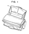
- FIGS. 1 and 2 are a schematic perspective view and a sectional view, respectively, of an image scanner according to an embodiment of the present invention.
- the image scanner has at its rear end a shooter 13 on which documents to be scanned are placed, as well as a paper feed apparatus disposed inside the scanner.
- the paper feed apparatus has a picking mechanism disposed in the vicinity of a paper supply opening of the shooter 13.
- the picking mechanism comprises a picking roller 1 and a picking arm 4.
- the picking roller 1 and picking arm 4 cooperate to successively pick a plurality of sheets of paper 21 (original documents of paper or any other medium carrying characters, figures, symbols, etc.) stacked on the shooter 13, one sheet at a time, from the bottom of the paper stack. Subsequently, the picking roller 1 transfers a sheet of paper to a predetermined standby position.
- the direction of transport of the sheets of paper 21 is indicated by an arrow.
- FIG. 3 is an enlarged view of a region A in FIG. 2, showing in detail the embodiment of the present invention.
- the picking roller 1 is disposed on the lower side and in the vicinity of the paper supply opening of the shooter 13.
- the picking arm 4 On the upper side of the picking roller 1, the picking arm 4, a gate 2, a paper separation pad 3 are disposed along the paper supply path, in this sequence.
- Reference numeral 31 denotes a holding member which holds the paper separation pad 3 and presses it against the outer circumferential surface of the picking roller 1.
- Reference numeral 33 denotes a guide sheet provided to cover a portion of the paper separation pad 3.
- Reference numeral 32 denotes guide arms, which are disposed on the upstream side of pressing arms 81 with respect to the paper entrance direction (i.e., the paper transport direction) such that the distal ends of the guide arms 32 are located in proximity to the picking roller 1.
- the holding member 31, the guide sheet 33, and the guide arms 32 will be described later.
- the picking roller 1 is formed of a material having a large friction coefficient, such as foam rubber.
- the gate 2 extends perpendicular to the entrance direction (i.e., the paper transport direction).
- the picking roller 1 is disposed so as not to change the transport direction of the sheet(s) of paper 21 during transport. That is, the picking roller 1 is disposed substantially perpendicular to the transport direction.
- the paper separation pad 3 in sliding contact with the picking roller 1 draws inside, a single sheet at a time, the sheets of paper 21 transported to the standby position. Therefore, the sheets of paper 21 are considered to reach the standby position when the leading edge of the sheets of paper 21 reaches a position at which the paper separation pad 3 is in contact with the picking roller 1 (see FIGS. 10 and 11).
- the picking arm 4 is driven such that its distal end moves vertically.
- the picking arm 4 is moved to and held at an upper position or wait position P1 (see FIG. 5).
- the picking arm 4 is moved to and held at a lower position or paper feed position P2 (see FIG. 5 as well).
- the picking arm 4 presses from above the sheets of paper 21 stacked on the shooter 13 in an area in the vicinity of the paper supply opening. Accordingly, as indicated by a solid line and a broken line in FIG.
- the paper feed position P2 of the picking arm 4 changes depending on the number of sheets of paper 21 (or the total thickness of stacked sheets of paper). As shown in FIG. 3, the paper supply opening is considered to be the clearance between the picking roller 1 and the gate 2 or a portion at which the sheets of paper 21 come into contact with the guide arms 32.
- FIGS. 4 and 5 are views showing a drive system for paper transport and picking-arm drive in the embodiment of the present invention.
- reference numeral 6 denotes a motor for paper transport whose output shaft rotates in the forward direction indicated by arrow A1. Via the gear train shown in FIGS. 4 and 5, the motor 6 drives the picking roller 1, the feed roller 11, and the feed roller 23 to thereby transport the sheets of paper 21.
- a picking-roller drive gear 20 for driving the picking roller 1 is equipped with a one-way clutch, so that the picking-roller drive gear 20 rotates only in the counterclockwise direction (paper transport direction) in FIGS. 4 and 5.
- the feed rollers 11 and 23 are shown by use of broken lines.
- Reference numeral 24 denotes follower rollers disposed to face the feed rollers 11 and 23, respectively.
- Reference numeral 8 denotes a picking-arm drive gear which has a pivot and is connected to the picking arm 4.
- Reference numeral 5 denotes a planetary gear which is rotatably coupled to a planetary gear frame 26 and is in meshing engagement with the picking-arm drive gear 8. Rotation of the feed roller 11 is transmitted to the planetary gear 5 via a gear train shown in FIGS. 4 and 5 to thereby drive the planetary gear 5.
- Reference numeral 27 denotes a planetary-gear frame stopper for restricting the pivoting range of the planetary gear frame 26.
- the motor 6 When the picking arm 4 is to be moved to and maintained at the lower position or paper feed position P2, the motor 6 is driven to rotate forward, so that the planetary gear 5 is disengaged from the picking arm drive gear 8. As a result, the picking arm 4 is positioned at the lower position.
- the motor 6 When the picking arm 4 is to be moved to and maintained at the upper position or wait position P1, the motor 6 is driven to rotate in reverse, so that the planetary gear 5 comes into meshing engagement with the picking arm drive gear 8 in order to move the picking arm 4 to the upper position.
- the details of the drive-source switchover mechanism using the planetary gear 5 will be described later.
- Reference numeral 7 denotes a picking-arm state detection sensor for detecting the picking arm 4 which is moved to the upper position as a result of reverse rotation of the motor 6 and meshing engagement of the planetary gear 5 with the picking-arm drive gear 8.
- the motor 6 is driven to rotate in the reverse direction until the picking-arm state detection sensor 7 outputs a signal (ON signal) indicating detection of the picking arm 4, so that the picking arm 4 is to be moved to the upper position.
- reference numeral 10 denotes a paper detection sensor disposed in the vicinity of the shooter 13.
- the paper detection sensor 10 is disposed at a position such that the paper detection sensor 10 maintains an OFF state when sheets of paper 21 are placed on the shooter 13 in a state in which the picking arm 4 is located at the lower position, but comes into an ON state when the sheets of paper 21 are placed on the shooter 13 in a state in which the picking arm 4 is located at the upper position.
- the picking arm 4 is moved to the upper position when the paper detection sensor 10 does not output a signal indicating detection of the presence of sheets of paper, but the picking arm 4 is not moved to the upper position when the paper detection sensor 10 outputs the signal indicating detection of the presence of sheets.
- Reference numeral 12 denotes a paper detection sensor disposed between the picking roller 1 and the feed roller 11 and adapted to detect presence/absence of a sheet of paper 21 between the picking roller 1 and the feed roller 11.
- the paper detection sensor 12 when the paper detection sensor 12 outputs signal indicating absence of a sheet of paper or when a sheet of paper is not picked, forward and reverse rotations of the motor 6 are repeated in order to move the distal end of the picking arm 4 vertically, so that the picking arm 4 hits the sheets of paper 21 stacked on the shooter 13.
- Reference numeral 25 denotes a paper-end detection sensor for detecting the leading and trailing ends of a sheet of paper 21.
- the paper-end detection sensor 25 detects the leading end of the sheet of paper 21
- the paper-end detection sensor 25 outputs a signal, in response to which a scanning operation is started.
- the scanning operation is stopped, and the feed roller 23 discharges the sheet of paper 21 to an unillustrated stacker or to the outside of the apparatus.
- the height of the shooter 13 is reduced in the vicinity of the paper supply opening in order to form a surface inclined with respect to the paper transport direction and forming a step 14.
- the drive source switchover mechanism using the planetary gear 5 will be described with reference to FIG. 5.
- the motor 6 is driven to rotate forward.
- the picking roller 1 is rotated in the counterclockwise direction (paper transport direction) via a gear train.
- the feed roller 11 is rotated in the clockwise direction (paper transport direction) via another gear train. Rotation of the feed roller 11 is transmitted via another gear train to the planetary gear 5 located at a wait position P3, so that the planetary gear 5 rotates counterclockwise about its own axis, and starts a clockwise revolving motion while maintaining meshing engagement with the picking-arm drive gear 8.
- the planetary gear 5 disengages from the picking-arm drive gear 8 and moves to a paper feed position P4.
- the picking arm 4 connected to the picking-arm drive gear 8 is moved downward by means of pressing force applied from a pressure applying element. Consequently, the picking arm 4 presses from above the sheets of paper 21 stacked on the shooter 13 in an area in the vicinity of the paper supply opening.
- the motor 6 is driven to rotate in reverse.
- the feed roller 11 rotates in the counterclockwise direction through drive transmitted via the corresponding gear train, but the picking roller 1 does not rotate, because the picking-roller drive gear 20 is equipped with a one-way clutch.
- the rotation of the feed roller 11 is transmitted to the planetary gear 5 via the corresponding gear train, so that the planetary gear 5 rotates clockwise about its own axis, and starts a counterclockwise revolving motion. Having started the revolving motion, the planetary gear 5 comes into meshing engagement with the picking-arm drive gear 8.
- the picking-arm drive gear 8 starts a counterclockwise pivoting motion.
- the picking arm 4 connected to the picking-arm drive gear 8 moves upward.
- the reverse rotation of the motor 6 for moving the picking arm 4 upward is continued until the picking-arm state detection sensor 7 outputs a signal indicating detection of the picking arm 4.
- the motor 6 can be used for paper transport and picking arm operation, the number of components and the size of the paper feed apparatus can be decreased. Further, provision of the picking-arm state detection sensor 7 enables accurate detection of the operation position of the picking arm 4, whose motion involves varying delay, because the planetary gear frame 26 is moved by means of frictional force. Further, the paper detection sensor 12 disposed between the picking and feed rollers enables the picking arm 4 to hit the sheets of paper 21 when a sheet of paper cannot be picked, thereby improving picking performance. Further, when the sheets of paper 21 are considered to form a beam, the arm length of the beam is reduced through provision of the step 14, so that the rigidity of the sheets of paper 21 can be reduced. Therefore, even when the sheets of paper 21 curl upward, the paper pressing force exerted by the picking arm can be reliably transmitted to the picking roller 1, so that the performance for picking the sheets of paper 21 is improved.
- FIG. 6 is an enlarged perspective view showing the picking roller 1 and its neighboring portions in the embodiment of the present invention.
- reference numeral 34 denotes a circumferential groove which is formed at an axially intermediate portion of the picking roller 1.
- the circumferential groove 34 may be provided at a single location, but may be formed at a plurality of locations if necessary.
- Reference numeral 35 denotes a paper guide disposed on the downstream side of the shooter 13 with respect to the paper transport direction and above the picking roller 1.
- Reference numeral 36 denotes an opening (or a roller opening) formed in the paper guide 35 and having a bridge portion 37 received in the circumferential groove 34. A portion of the outer circumference surface of the picking roller 1 is exposed to the outside through the opening 36 of the paper guide 35.
- An arrow in FIG. 6 indicates the paper transport direction.
- the bridge portion 37 eliminates the possibility that the sheets of paper 21 being transported in the direction of the arrow become caught between the picking roller 1 and the opening 36 with a resultant paper jam. Therefore, the sheets of paper 21 can be supplied smoothly and reliably.
- FIGS. 7 and 8 are a perspective view and an exploded perspective view, respectively, showing an integrally-molded gate component used in the embodiment of the present invention.
- the gate 2 and guide arms 32 are formed integrally with the holding member 31, to which the paper separation pad 3 is attached.
- the gate 2, the guide arms 32, and the holding member 31 constitute an integrally-molded gate component 29.
- a pivot shaft 15 is provided at one end of the holding member 31 carrying the gate 2 and the paper separation pad 3 such that the pivot shaft 15 is aligned with the tip end of the gate 2.
- a spring 16 (see FIG. 3) for producing pressure for paper separation is engaged with the other end of the holding member 31, so that the holding member 31 is urged toward the picking roller 1.
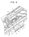
- FIG. 9 is a perspective view showing a state in which the gate component 29 shown in FIG. 7 is attached to the apparatus.
- this structure minimizes the distance X between the gate 2 and the paper separation pad 3 shown in FIG. 3, the possibility of the leading end of a sheet of paper being turned up between the gate 2 and the paper separation pad 3 can be minimized. Therefore, the paper feed performance is improved, and the gate 2 and paper separation pad 3 can be reduced in size in order to reduce the overall size of the paper feed apparatus. Further, since the axis of the pivot shaft 15 is aligned with the tip end of the gate 2, a stable gate gap (clearance) can be secured without regard to variation in thickness of the paper separation pad 3 among products or friction of the paper separation pad 3 caused by paper feed.
- the gate component 29 is molded to have a portion corresponding to the gate 2 and to enable attachment of the paper separation pad 3 and a pad fixation wire spring 17.
- the paper separation pad 3 is fixed through use of the pad fixation wire spring 17.
- a horizontally extending portion of the pad fixation wire spring 17 is engaged with the upper portion of the gate 2, and the opposite ends of the pad fixation wire spring 17 are inserted into through holes formed in the paper separation pad 3 and further into unillustrated through holes formed in the holding member 31 in the vicinity of the gate 2.
- the gate 2 and the paper separation pad 3 can be reduced in size in order to reduced the overall size of the paper feed apparatus. Further, since exfoliation of the paper separation pad 3 or other problems hardly occur, paper separation can be performed stably. Since attachment of the paper separation pad 3 requires no time for drying, attachment of the paper separation pad 3 to the gate component 29 can be completed within a shorter period of time than in the case where adhesive is used.
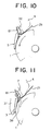
- FIG. 10 is a view used for description of action of the guide arms 32.
- the leading end of a sheet of paper 21 tends to lift, because of the force applied from the picking arm 4 to the picking roller 1. Accordingly, if the guide arms 32 were not present, the sheet of paper 21 would abut the pressing arms 81 or the paper separation pad 3 at a larger abutting angle, with the result that the leading end of the sheet of paper 21 would turn up.
- the guide arms 32 are disposed on the upstream side of the pressing arms 81 with respect to the paper transport direction such that their tip ends are located in proximity to the picking roller 1. Therefore, the leading end of the sheet of paper 21 is pushed by the guide arms 32 toward the picking roller 1, so that the angle at which the sheet of paper 21 abuts the pressing arms 81 or the paper separation pad 3 is decreased, and thus an upturn phenomenon is prevented.
- the guide arms 32 are formed integrally with the holding member 31 from the same resin material.
- the guide arms 32 may be formed from a metallic material having elasticity, such as spring material.
- the guide arms 32 may be integrated with the holding member 31 through so-called insert molding.
- the guide arms 32 may be formed integrally with the pressing arms 81 by use of metallic material.
- FIG. 11 is a view used for description of paper guide action in another embodiment of the present invention.
- reference numeral 38 denotes a guide member which is formed integrally with the holding member 31 or the gate 2 to be located on the upstream side of the pressing arms 81 or the paper separation pad 3.
- the surface of the guide member 38 has an inclination angle, with respect to the paper transport direction, smaller than that of the pressing arms 81 or the paper separation pad 3.
- the guide member 38 is formed such that the guide member 38 does not contact the picking roller 1, and the leading end of a sheet of paper 21 can abut the guide member 38 and slide therealong.
- the leading end of the sheet of paper 21 is guided downward by the guide member 38, so that the angle at which the sheet of paper 21 abuts the pressing arms 81 or the paper separation pad 3 is decreased, thus preventing an upturn phenomenon.
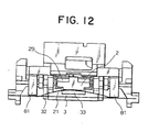
- FIG. 12 is a view showing a paper supply opening and its neighboring portions in the embodiment of the present invention.
- the sheet of paper 21 is transported away from the viewer.
- a guide sheet 33 covering a portion of the paper separation pad 3 is formed of a material having a coefficient of friction lower than that of the material constituting the paper separation pad 3. Further, the guide sheet 33 is disposed such that the guide sheet 33 does not contact the picking roller (not shown in FIG. 12), and the leading end of a sheet of paper 21 can abut the guide sheet 33 and slide therealong.
- the above-described structure provides an upturn-preventing action. That is, even when a sheet of paper 21 is supplied in a state in which the center portion thereof is lifted as shown in FIG. 12, the leading end of the sheet of paper 21 slides downward along the surface of the guide sheet 33 after abutment with the surface thereof, so that the leading end of the sheet of paper 21 does not turn up.
- the structure shown in FIG. 12 is particularly effective when the sheet of paper 21 is thin.
- the guide member 38 integrated with the gate 2 also provides the above-described upturn-preventing action.
- the paper feed apparatus can be made compact.
- the gate extends substantially perpendicular to the paper transport direction, no component force is produced in the direction perpendicular to the sheets of paper, so that paper separation performance is improved.
- a circumferential groove is formed at an axially center portion of the picking roller; an opening is formed in the paper guide such that the opening has a bridge portion fitted into the circumferential groove; and a portion of the picking roller is exposed to the outside through the opening. Therefore, the sheets of paper can be supplied smoothly without becoming caught.
- the guide arms are disposed on the upstream side of the pressing arms in sliding contact with the picking arm, so that upturn of the leading end of the sheet of paper can be prevented.
- the guide sheet formed of a material having a coefficient of friction lower than that of the separation pad is disposed to cover a portion of the separation pad, the lifted leading end of the sheet of paper can be urged downward for correction, so that upturn of the leading end of the sheet of paper can be prevented.
- the surface of the guide member disposed between the gate and the separation pad has an inclination angle, with respect to the paper transport direction, smaller than that of the surface of the separation pad, upturn of the leading end of the sheet of paper can be prevented as in the above-described case.
Landscapes
- Engineering & Computer Science (AREA)
- Mechanical Engineering (AREA)
- Sheets, Magazines, And Separation Thereof (AREA)
Description
- The present invention relates to a paper feed apparatus, and more particularly to a bottom-drawing-type paper feed apparatus which is suitable for, for example, an image scanner and which has an improved sheet separation performance, eliminates necessity of a pre-operation before setting of sheets of paper to thereby facilitate operation, and prevents occurrence of a paper jam and/or upturn of a leading end of a sheet.
- In general, an image scanner is provided with an automatic paper feed apparatus which enables the image scanner to automatically transport and read a huge amount of documents. Such an automatic paper feed apparatus comprises a picking mechanism for transporting a plurality of sheets of paper stacked on a shooter to a predetermined standby position; a separation mechanism for drawing inside a sheet of paper at a time from the standby position; a feed mechanism for feeding the separated sheet; and a discharge mechanism for discharging the sheet to a stacker or the outside of the scanner after the sheet has been scanned. Recently, such an automatic paper feed apparatus has been controlled by means of a microprocessor.
- FIG. 13 is an explanatory view showing a main portion of a conventional paper feed apparatus. As shown in FIG. 13, a
picking roller 72 and aseparation roller 73 are drivingly linked via agear 83 so that thepicking roller 72 and theseparation roller 73 rotate in the same direction; and theseparation roller 73 is drivingly linked to afeed roller 74 via agear 79. Further, apressing arm 81 is disposed in sliding contact with thepicking roller 72, and aseparation pad 80 is disposed in sliding contact with theseparation roller 73. Moreover, agate 84 is disposed on a paper feed path between thepicking roller 72 and theseparation roller 73. - The
pressing arm 81 is provided in order to enable reliable transport of sheets of paper set on ashooter 71 and is formed from a spring member. One end of thepressing arm 81 is fixed to an unillustrated frame, and the other end of thepressing arm 81 is biased toward the pickingroller 72 to thereby come into contact with the top sheet of paper while applying a certain pressing force to the sheets of paper. By means of frictional force which is generated between thepicking roller 72 and the sheets of paper due to the pressing force, the sheets of paper are transported from theshooter 71 to theseparation roller 73. - The
gate 84 is provided so as to secure a clearance in the thickness direction of sheets on the paper feed path in order to enable passage of a few sheets of paper, thereby enabling reliable transport of the sheets. Thegate 84 has a paper-abutting surface which forms an acute angle with respect to the paper transport direction along the paper feed path. - A one-way clutch is attached to each of the
picking roller 72, theseparation roller 73, and thedischarge roller 75 such that theseparation roller 73 rotates in the counterclockwise direction in FIG. 13, and thedischarge roller 75 rotates in the clockwise direction (paper transport direction) only. Further, asensor 82 for detecting the leading end of each sheet of paper is disposed along the paper feed path in the vicinity of and on the downstream side of theseparation roller 73. Further, asensor 85 for detecting the leading and trailing ends of each sheet of paper is disposed along the paper feed path in the vicinity of and on the downstream side of thefeed roller 74. - In the above-described automatic paper feed apparatus, when a
pulley 76 connected to an unillustrated motor is rotated in the counterclockwise direction, abelt 77 engaged with thepulley 76 causes thefeed roller 74 to rotate in the counterclockwise direction, or in a direction opposite the paper transport direction. At this time, thedischarge roller 75 does not rotate even when thebelt 77 moves. Meanwhile, the pickingroller 72 and theseparation roller 73 are rotated in the counterclockwise direction (paper transport direction) viagears shooter 71 by thepicking roller 72 and is transported toward theseparation roller 73. If a plurality of sheets of paper are picked erroneously, thegate 84 and theseparation pad 80 prevent transfer of the plurality of sheets, so that only a single sheet of paper in close contact with thepicking roller 72 and theseparation roller 73 is transported toward thefeed roller 74. Therefore, transportation of two sheets (double feed or a like) problem does not occur. - Even when the leading end of the transported sheet of paper reaches the
feed roller 74, the sheet of paper is not supplied to thefeed roller 74 instantaneously but is stopped there for a short period of time, because thefeed roller 74 is rotating in the counterclockwise direction, which is opposite the paper transport direction. During this period, positioning of the leading end of the sheet is performed. The stop time is controlled on the basis of a predetermined number of pulses or a predetermined period of time after thesensor 82 detects the leading end of a sheet of paper. After elapse of the predetermined period of time, the unillustrated motor rotates in the reverse direction in order to rotate thepulley 76 in the clockwise direction. Therefore, thefeed roller 74 and thedischarge roller 75 are also rotated in the clockwise direction via thebelt 77. As a result, the sheet of paper is transported by thefeed roller 74 to areading mechanism 78. Immediately before the leading end of the sheet of paper reaches thereading mechanism 78, the leading end is detected by thesensor 85. In response to a detection signal generated by thesensor 85, the read operation is started. When thesensor 85 detects the trailing end of the sheet of paper, the read operation is ended, and thedischarge roller 75 is operated to discharge the sheet of paper onto an unillustrated stacker. - In the above-described automatic paper feed apparatus, when, as shown in FIG. 14A, a large number of sheets of
paper 90 are placed onto theshooter 71, the sheets ofpaper 90 must be aligned in a staggered manner beforehand such that the leading ends of the sheets ofpaper 90 form a knife-edge-like shape 91, as shown in FIG. 14B, in order to make it easy to feeding the sheets of paper to theseparation roller 73. - The above-described conventional paper feed apparatus has the following drawbacks.
- Since the gate―which forms a clearance in the thickness direction of sheets of paper on the paper feed path―extends at an acute angle with respect to the paper transport direction, a vertical component force is generated and is applied to the sheets of paper, resulting in an impairment in paper separation performance.
- Further, when a large number of sheets of paper are placed onto the shooter, the sheets of paper must be aligned in a staggered manner beforehand such that the leading ends of the sheets of paper form a knife-edge-like shape. However, this pre-operation is considerably cumbersome, and is sometimes neglected or forgotten. In this case, sheets of paper cannot be supplied smoothly.
- Moreover, the separation roller is disposed between the picking roller and the feed roller; the pressing arm is disposed in sliding contact with the picking roller; and the separation pad is disposed in sliding contact with the separation roller. Therefore, the transport mechanism portion of the paper feed apparatus has a relatively large size.
- Further, since the picking roller is disposed such that a portion of the outer circumference of the picking roller is exposed to the outside from an opening provided in a paper guide, when the picking roller picks and transfers a sheet of paper, the sheet may be caught between the picking roller and the paper guide, resulting in occurrence of a paper jam and stoppage of paper feed.
- Moreover, although the separation pad is disposed to prevent so-called double feed in which a plurality of sheets of paper are supplied, the disposition of the separation pad causes an undesirable phenomenon such that the leading end of a sheet engages the separation pad and is turned up.
- The patent application publication JP 59-18 6839, which is considered to represent the closest prior art, discloses the preamble of
claim 1. - In view of the foregoing problems involved in conventional techniques, it is an object of the present invention to provide a paper feed apparatus which has an improved sheet separation performance, facilitates operation, and prevents occurrence of paper jam of a leading end of a sheet.
- It is an another object of the present invention to provide a paper feed apparatus which has an improved sheet separation performance, facilitates operation, and prevents occurrence of upturn of a leading end of a sheet.
- In order to achieve the above-described object, the present invention provides a paper feed apparatus comprising: a picking roller successively picking a plurality of sheets of paper stacked on the shooter from the bottom of the paper stack, transporting the sheets of paper to a standby position and having one or a plurality of circumferential grooves formed on it; a gate extending substantially perpendicular to a paper transport direction and forming a predetermined clearance between the gate and the picking roller; a separation pad disposed in sliding contact with the outer circumferential surface of the picking roller and adapted to draw inside a single sheet of paper at a time from the standby station; a picking arm driven to move to an upper position when sheets of paper are placed on the shooter, and to a lower position when the sheets of paper are fed in order to press the sheets of paper placed on the shooter toward the outer circumferential surface of the picking roller in an area in the vicinity of a paper supply opening; and a paper guide disposed above the picking roller and having an opening and a bridge portion extending across the opening and fitted in a circumferential groove formed in an axially center portion of the picking roller.
- The present invention also provides a paper feed apparatus comprising: a picking roller successively picking a plurality of sheets of paper stacked on the shooter from the bottom of the paper stack and transporting the sheets of paper to a standby position; a gate extending substantially perpendicular to a paper transport direction and forming a predetermined clearance between the gate and the picking roller; a separation pad disposed in sliding contact with the outer circumferential surface of the picking roller and adapted to draw inside a single sheet of paper at a time from the standby station; a picking arm driven to move to an upper position when sheets of paper are placed on the shooter, and to a lower position when the sheets of paper are fed in order to press the sheets of paper placed on the shooter toward the outer circumferential surface of the picking roller in an area in the vicinity of a paper supply opening; a pressing arm formed of an elastic material and disposed in sliding contact with the picking roller; and guide arms disposed on the upstream side of the pressing arm with respect to the paper transport direction such that their tip ends are located in proximity to the picking roller.
- The present invention further provides a paper feed apparatus comprising: a picking roller successively picking a plurality of sheets of paper stacked on the shooter from the bottom of the paper stack and transporting the sheets of paper to a standby position; a gate extending substantially perpendicular to a paper transport direction and forming a predetermined clearance between the gate and the picking roller; a separation pad disposed in sliding contact with the outer circumferential surface of the picking roller and adapted to draw inside a single sheet of paper at a time from the standby station; a picking arm driven to move to an upper position when sheets of paper are placed on the shooter, and to a lower position when the sheets of paper are fed in order to press the sheets of paper placed on the shooter toward the outer circumferential surface of the picking roller in an area in the vicinity of a paper supply opening; and a guide sheet formed of a material having a coefficient of friction lower than that of the material constituting the separation pad, the guide sheet being disposed to cover a portion of the separation pad such that the guide sheet does not contact the picking roller, and such that the leading end of the sheet of paper can abut and slide along the guide sheet.
- The present invention further provides a paper feed apparatus comprising: a picking roller successively picking a plurality of sheets of paper stacked on the shooter from the bottom of the paper stack and transporting the sheets of paper to a standby position; a gate extending substantially perpendicular to a paper transport direction and forming a predetermined clearance between the gate and the picking roller; a separation pad disposed in sliding contact with the outer circumferential surface of the picking roller and adapted to draw inside a single sheet of paper at a time from the standby station; a picking arm driven to move to an upper position when sheets of paper are placed on the shooter, and to a lower position when the sheets of paper are fed in order to press the sheets of paper placed on the shooter toward the outer circumferential surface of the picking roller in an area in the vicinity of a paper supply opening; and a guide member disposed between the gate and the separation pad with respect to the paper transport direction, a surface of the guide member having an inclination angle with respect to the paper transport direction smaller than that of a surface of the separation pad, and the guide member being provided integrally with the gate or a holding member supporting the separation pad such that the guide member does not contact the picking roller and such that the leading end of the sheet of paper can abut and slide along the guide member.
-
- FIGS. 1 and 2 are views showing an image scanner according to an embodiment of the present invention, wherein FIG. 1 is a perspective view of the image scanner, and FIG. 2 is a sectional view of the image scanner;
- FIG. 3 is an enlarged view of a portion A shown in FIG. 2;
- FIGS. 4 and 5 are sectional views showing a drive system for paper transport and picking arm drive in the embodiment of the present invention;
- FIG. 6 is an enlarged perspective view showing a picking roller and its neighboring portions in the embodiment of the present invention;
- FIGS. 7 and 8 are views showing an integrally-molded gate component used in the embodiment of the present invention, wherein FIG. 7 is a perspective view of the gate component, and FIG. 8 is an exploded perspective view of the gate component;
- FIG. 9 is a perspective view showing a state in which the gate component shown in FIG. 7 is attached to the apparatus;
- FIG. 10 is a view used for description of action of guide arms;
- FIG. 11 is a view used for description of paper guide action in another embodiment of the present invention;
- FIG. 12 is a view showing a paper supply opening and its neighboring portions in the embodiment of the present invention;
- FIG. 13 is a view showing a conventional paper feed apparatus: and
- FIGS. 14A and 14B are side views of a large number of stacked sheets of paper, wherein FIG. 14A shows a state before an operation of aligning the sheets in a staggered manner, and FIG. 14B shows a state after that the alignment operation.
-
- Embodiments of the present invention will now be described.
- FIGS. 1 and 2 are a schematic perspective view and a sectional view, respectively, of an image scanner according to an embodiment of the present invention. As shown in FIGS. 1 and 2, the image scanner has at its rear end a
shooter 13 on which documents to be scanned are placed, as well as a paper feed apparatus disposed inside the scanner. The paper feed apparatus has a picking mechanism disposed in the vicinity of a paper supply opening of theshooter 13. The picking mechanism comprises a pickingroller 1 and apicking arm 4. The pickingroller 1 and pickingarm 4 cooperate to successively pick a plurality of sheets of paper 21 (original documents of paper or any other medium carrying characters, figures, symbols, etc.) stacked on theshooter 13, one sheet at a time, from the bottom of the paper stack. Subsequently, the pickingroller 1 transfers a sheet of paper to a predetermined standby position. In FIG. 2, the direction of transport of the sheets ofpaper 21 is indicated by an arrow. - FIG. 3 is an enlarged view of a region A in FIG. 2, showing in detail the embodiment of the present invention. As shown in FIG. 3, the picking
roller 1 is disposed on the lower side and in the vicinity of the paper supply opening of theshooter 13. On the upper side of the pickingroller 1, the pickingarm 4, agate 2, apaper separation pad 3 are disposed along the paper supply path, in this sequence.Reference numeral 31 denotes a holding member which holds thepaper separation pad 3 and presses it against the outer circumferential surface of the pickingroller 1.Reference numeral 33 denotes a guide sheet provided to cover a portion of thepaper separation pad 3.Reference numeral 32 denotes guide arms, which are disposed on the upstream side of pressingarms 81 with respect to the paper entrance direction (i.e., the paper transport direction) such that the distal ends of theguide arms 32 are located in proximity to the pickingroller 1. The holdingmember 31, theguide sheet 33, and theguide arms 32 will be described later. - The picking
roller 1 is formed of a material having a large friction coefficient, such as foam rubber. Thegate 2, in cooperation with the pickingroller 1, forms a clearance (e.g., of a size of about 1 mm) through which a few sheets ofpaper 21 can pass. Thegate 2 extends perpendicular to the entrance direction (i.e., the paper transport direction). The pickingroller 1 is disposed so as not to change the transport direction of the sheet(s) ofpaper 21 during transport. That is, the pickingroller 1 is disposed substantially perpendicular to the transport direction. Thepaper separation pad 3 in sliding contact with the pickingroller 1 draws inside, a single sheet at a time, the sheets ofpaper 21 transported to the standby position. Therefore, the sheets ofpaper 21 are considered to reach the standby position when the leading edge of the sheets ofpaper 21 reaches a position at which thepaper separation pad 3 is in contact with the picking roller 1 (see FIGS. 10 and 11). - The picking
arm 4 is driven such that its distal end moves vertically. When the sheets ofpaper 21 are to be placed on theshooter 13, the pickingarm 4 is moved to and held at an upper position or wait position P1 (see FIG. 5). When the sheets ofpaper 21 placed on theshooter 13 are to be fed, the pickingarm 4 is moved to and held at a lower position or paper feed position P2 (see FIG. 5 as well). When the pickingarm 4 is held at the paper feed position, due to a pressing force applied from an unillustrated pressure-applying element to the pickingarm 4, the pickingarm 4 presses from above the sheets ofpaper 21 stacked on theshooter 13 in an area in the vicinity of the paper supply opening. Accordingly, as indicated by a solid line and a broken line in FIG. 3, the paper feed position P2 of the pickingarm 4 changes depending on the number of sheets of paper 21 (or the total thickness of stacked sheets of paper). As shown in FIG. 3, the paper supply opening is considered to be the clearance between the pickingroller 1 and thegate 2 or a portion at which the sheets ofpaper 21 come into contact with theguide arms 32. - In the structure shown in FIG. 3, since the
gate 2 extends perpendicular to the paper transport direction, no component force is generated in the direction perpendicular to the paper transport direction, so that the multi-feed phenomenon (transportation of a plurality of sheets) does not occur, thus improving the paper separation performance. Further, satisfactory picking performance is secured; even when a large number of sheets ofpaper 21 are placed on theshooter 13, as shown in FIG. 14A, the sheets ofpaper 21 can be placed as they are without being staggered. - FIGS. 4 and 5 are views showing a drive system for paper transport and picking-arm drive in the embodiment of the present invention. In FIGS. 4 and 5,
reference numeral 6 denotes a motor for paper transport whose output shaft rotates in the forward direction indicated by arrow A1. Via the gear train shown in FIGS. 4 and 5, themotor 6 drives the pickingroller 1, thefeed roller 11, and thefeed roller 23 to thereby transport the sheets ofpaper 21. A picking-roller drive gear 20 for driving the pickingroller 1 is equipped with a one-way clutch, so that the picking-roller drive gear 20 rotates only in the counterclockwise direction (paper transport direction) in FIGS. 4 and 5. In FIGS. 4 and 5, thefeed rollers Reference numeral 24 denotes follower rollers disposed to face thefeed rollers -
Reference numeral 8 denotes a picking-arm drive gear which has a pivot and is connected to the pickingarm 4.Reference numeral 5 denotes a planetary gear which is rotatably coupled to aplanetary gear frame 26 and is in meshing engagement with the picking-arm drive gear 8. Rotation of thefeed roller 11 is transmitted to theplanetary gear 5 via a gear train shown in FIGS. 4 and 5 to thereby drive theplanetary gear 5.Reference numeral 27 denotes a planetary-gear frame stopper for restricting the pivoting range of theplanetary gear frame 26. - When the picking
arm 4 is to be moved to and maintained at the lower position or paper feed position P2, themotor 6 is driven to rotate forward, so that theplanetary gear 5 is disengaged from the pickingarm drive gear 8. As a result, the pickingarm 4 is positioned at the lower position. When the pickingarm 4 is to be moved to and maintained at the upper position or wait position P1, themotor 6 is driven to rotate in reverse, so that theplanetary gear 5 comes into meshing engagement with the pickingarm drive gear 8 in order to move the pickingarm 4 to the upper position. The details of the drive-source switchover mechanism using theplanetary gear 5 will be described later. -
Reference numeral 7 denotes a picking-arm state detection sensor for detecting the pickingarm 4 which is moved to the upper position as a result of reverse rotation of themotor 6 and meshing engagement of theplanetary gear 5 with the picking-arm drive gear 8. By use of the picking-armstate detection sensor 7, themotor 6 is driven to rotate in the reverse direction until the picking-armstate detection sensor 7 outputs a signal (ON signal) indicating detection of the pickingarm 4, so that the pickingarm 4 is to be moved to the upper position. - In FIG. 4,
reference numeral 10 denotes a paper detection sensor disposed in the vicinity of theshooter 13. Thepaper detection sensor 10 is disposed at a position such that thepaper detection sensor 10 maintains an OFF state when sheets ofpaper 21 are placed on theshooter 13 in a state in which thepicking arm 4 is located at the lower position, but comes into an ON state when the sheets ofpaper 21 are placed on theshooter 13 in a state in which thepicking arm 4 is located at the upper position. By use of thepaper detection sensor 10, during initialization or reset operation, the pickingarm 4 is moved to the upper position when thepaper detection sensor 10 does not output a signal indicating detection of the presence of sheets of paper, but the pickingarm 4 is not moved to the upper position when thepaper detection sensor 10 outputs the signal indicating detection of the presence of sheets. -
Reference numeral 12 denotes a paper detection sensor disposed between the pickingroller 1 and thefeed roller 11 and adapted to detect presence/absence of a sheet ofpaper 21 between the pickingroller 1 and thefeed roller 11. By use of thepaper detection sensor 12, when thepaper detection sensor 12 outputs signal indicating absence of a sheet of paper or when a sheet of paper is not picked, forward and reverse rotations of themotor 6 are repeated in order to move the distal end of the pickingarm 4 vertically, so that the pickingarm 4 hits the sheets ofpaper 21 stacked on theshooter 13. -
Reference numeral 25 denotes a paper-end detection sensor for detecting the leading and trailing ends of a sheet ofpaper 21. When the paper-end detection sensor 25 detects the leading end of the sheet ofpaper 21, the paper-end detection sensor 25 outputs a signal, in response to which a scanning operation is started. When the paper-end detection sensor 25 detects the trailing end of the sheet ofpaper 21, the scanning operation is stopped, and thefeed roller 23 discharges the sheet ofpaper 21 to an unillustrated stacker or to the outside of the apparatus. - The height of the
shooter 13 is reduced in the vicinity of the paper supply opening in order to form a surface inclined with respect to the paper transport direction and forming astep 14. - Next, the drive source switchover mechanism using the
planetary gear 5 will be described with reference to FIG. 5. When the pickingarm 4 is to be moved to and maintained at the lower position or paper feed position, themotor 6 is driven to rotate forward. At this time, the pickingroller 1 is rotated in the counterclockwise direction (paper transport direction) via a gear train. Further, thefeed roller 11 is rotated in the clockwise direction (paper transport direction) via another gear train. Rotation of thefeed roller 11 is transmitted via another gear train to theplanetary gear 5 located at a wait position P3, so that theplanetary gear 5 rotates counterclockwise about its own axis, and starts a clockwise revolving motion while maintaining meshing engagement with the picking-arm drive gear 8. Subsequently, having started the revolving motion, theplanetary gear 5 disengages from the picking-arm drive gear 8 and moves to a paper feed position P4. At this time, the pickingarm 4 connected to the picking-arm drive gear 8 is moved downward by means of pressing force applied from a pressure applying element. Consequently, the pickingarm 4 presses from above the sheets ofpaper 21 stacked on theshooter 13 in an area in the vicinity of the paper supply opening. - When the picking
arm 4 is to be moved to and maintained at the upper position or wait position, themotor 6 is driven to rotate in reverse. At this time, thefeed roller 11 rotates in the counterclockwise direction through drive transmitted via the corresponding gear train, but the pickingroller 1 does not rotate, because the picking-roller drive gear 20 is equipped with a one-way clutch. The rotation of thefeed roller 11 is transmitted to theplanetary gear 5 via the corresponding gear train, so that theplanetary gear 5 rotates clockwise about its own axis, and starts a counterclockwise revolving motion. Having started the revolving motion, theplanetary gear 5 comes into meshing engagement with the picking-arm drive gear 8. Having come into meshing engagement with theplanetary gear 5, the picking-arm drive gear 8 starts a counterclockwise pivoting motion. As a result, the pickingarm 4 connected to the picking-arm drive gear 8 moves upward. The reverse rotation of themotor 6 for moving the pickingarm 4 upward is continued until the picking-armstate detection sensor 7 outputs a signal indicating detection of the pickingarm 4. - In the structure shown in FIGS. 4 and 5, since the
motor 6 can be used for paper transport and picking arm operation, the number of components and the size of the paper feed apparatus can be decreased. Further, provision of the picking-armstate detection sensor 7 enables accurate detection of the operation position of the pickingarm 4, whose motion involves varying delay, because theplanetary gear frame 26 is moved by means of frictional force. Further, thepaper detection sensor 12 disposed between the picking and feed rollers enables the pickingarm 4 to hit the sheets ofpaper 21 when a sheet of paper cannot be picked, thereby improving picking performance. Further, when the sheets ofpaper 21 are considered to form a beam, the arm length of the beam is reduced through provision of thestep 14, so that the rigidity of the sheets ofpaper 21 can be reduced. Therefore, even when the sheets ofpaper 21 curl upward, the paper pressing force exerted by the picking arm can be reliably transmitted to the pickingroller 1, so that the performance for picking the sheets ofpaper 21 is improved. - FIG. 6 is an enlarged perspective view showing the picking
roller 1 and its neighboring portions in the embodiment of the present invention. In FIG. 6,reference numeral 34 denotes a circumferential groove which is formed at an axially intermediate portion of the pickingroller 1. Thecircumferential groove 34 may be provided at a single location, but may be formed at a plurality of locations if necessary.Reference numeral 35 denotes a paper guide disposed on the downstream side of theshooter 13 with respect to the paper transport direction and above the pickingroller 1.Reference numeral 36 denotes an opening (or a roller opening) formed in thepaper guide 35 and having abridge portion 37 received in thecircumferential groove 34. A portion of the outer circumference surface of the pickingroller 1 is exposed to the outside through theopening 36 of thepaper guide 35. An arrow in FIG. 6 indicates the paper transport direction. - The
bridge portion 37 eliminates the possibility that the sheets ofpaper 21 being transported in the direction of the arrow become caught between the pickingroller 1 and theopening 36 with a resultant paper jam. Therefore, the sheets ofpaper 21 can be supplied smoothly and reliably. - FIGS. 7 and 8 are a perspective view and an exploded perspective view, respectively, showing an integrally-molded gate component used in the embodiment of the present invention. As shown in FIGS. 7 and 8, the
gate 2 and guidearms 32 are formed integrally with the holdingmember 31, to which thepaper separation pad 3 is attached. Thegate 2, theguide arms 32, and the holdingmember 31 constitute an integrally-moldedgate component 29. Apivot shaft 15 is provided at one end of the holdingmember 31 carrying thegate 2 and thepaper separation pad 3 such that thepivot shaft 15 is aligned with the tip end of thegate 2. A spring 16 (see FIG. 3) for producing pressure for paper separation is engaged with the other end of the holdingmember 31, so that the holdingmember 31 is urged toward the pickingroller 1. FIG. 9 is a perspective view showing a state in which thegate component 29 shown in FIG. 7 is attached to the apparatus. - Since this structure minimizes the distance X between the
gate 2 and thepaper separation pad 3 shown in FIG. 3, the possibility of the leading end of a sheet of paper being turned up between thegate 2 and thepaper separation pad 3 can be minimized. Therefore, the paper feed performance is improved, and thegate 2 andpaper separation pad 3 can be reduced in size in order to reduce the overall size of the paper feed apparatus. Further, since the axis of thepivot shaft 15 is aligned with the tip end of thegate 2, a stable gate gap (clearance) can be secured without regard to variation in thickness of thepaper separation pad 3 among products or friction of thepaper separation pad 3 caused by paper feed. - As shown in FIGS. 7 and 8, the
gate component 29 is molded to have a portion corresponding to thegate 2 and to enable attachment of thepaper separation pad 3 and a padfixation wire spring 17. Thepaper separation pad 3 is fixed through use of the padfixation wire spring 17. Specifically, a horizontally extending portion of the padfixation wire spring 17 is engaged with the upper portion of thegate 2, and the opposite ends of the padfixation wire spring 17 are inserted into through holes formed in thepaper separation pad 3 and further into unillustrated through holes formed in the holdingmember 31 in the vicinity of thegate 2. - Since the above structure reduces the space required for mechanical fixation, the
gate 2 and thepaper separation pad 3 can be reduced in size in order to reduced the overall size of the paper feed apparatus. Further, since exfoliation of thepaper separation pad 3 or other problems hardly occur, paper separation can be performed stably. Since attachment of thepaper separation pad 3 requires no time for drying, attachment of thepaper separation pad 3 to thegate component 29 can be completed within a shorter period of time than in the case where adhesive is used. - Next, action of the
guide arms 32 will be described. FIG. 10 is a view used for description of action of theguide arms 32. As shown in FIG. 10, the leading end of a sheet ofpaper 21 tends to lift, because of the force applied from the pickingarm 4 to the pickingroller 1. Accordingly, if theguide arms 32 were not present, the sheet ofpaper 21 would abut thepressing arms 81 or thepaper separation pad 3 at a larger abutting angle, with the result that the leading end of the sheet ofpaper 21 would turn up. - By contrast, in the present invention, the
guide arms 32 are disposed on the upstream side of thepressing arms 81 with respect to the paper transport direction such that their tip ends are located in proximity to the pickingroller 1. Therefore, the leading end of the sheet ofpaper 21 is pushed by theguide arms 32 toward the pickingroller 1, so that the angle at which the sheet ofpaper 21 abuts thepressing arms 81 or thepaper separation pad 3 is decreased, and thus an upturn phenomenon is prevented. - In the embodiment of the present invention, the
guide arms 32 are formed integrally with the holdingmember 31 from the same resin material. However, theguide arms 32 may be formed from a metallic material having elasticity, such as spring material. In this case, theguide arms 32 may be integrated with the holdingmember 31 through so-called insert molding. Alternatively, theguide arms 32 may be formed integrally with thepressing arms 81 by use of metallic material. - FIG. 11 is a view used for description of paper guide action in another embodiment of the present invention. In FIG. 11,
reference numeral 38 denotes a guide member which is formed integrally with the holdingmember 31 or thegate 2 to be located on the upstream side of thepressing arms 81 or thepaper separation pad 3. The surface of theguide member 38 has an inclination angle, with respect to the paper transport direction, smaller than that of thepressing arms 81 or thepaper separation pad 3. Theguide member 38 is formed such that theguide member 38 does not contact the pickingroller 1, and the leading end of a sheet ofpaper 21 can abut theguide member 38 and slide therealong. - In the above-described structure, as in the case of the
guide arms 32 shown in FIG. 10, the leading end of the sheet ofpaper 21 is guided downward by theguide member 38, so that the angle at which the sheet ofpaper 21 abuts thepressing arms 81 or thepaper separation pad 3 is decreased, thus preventing an upturn phenomenon. - FIG. 12 is a view showing a paper supply opening and its neighboring portions in the embodiment of the present invention. In FIG. 12, the sheet of
paper 21 is transported away from the viewer. Aguide sheet 33 covering a portion of thepaper separation pad 3 is formed of a material having a coefficient of friction lower than that of the material constituting thepaper separation pad 3. Further, theguide sheet 33 is disposed such that theguide sheet 33 does not contact the picking roller (not shown in FIG. 12), and the leading end of a sheet ofpaper 21 can abut theguide sheet 33 and slide therealong. - The above-described structure provides an upturn-preventing action. That is, even when a sheet of
paper 21 is supplied in a state in which the center portion thereof is lifted as shown in FIG. 12, the leading end of the sheet ofpaper 21 slides downward along the surface of theguide sheet 33 after abutment with the surface thereof, so that the leading end of the sheet ofpaper 21 does not turn up. The structure shown in FIG. 12 is particularly effective when the sheet ofpaper 21 is thin. - In the structure shown in FIG. 11, the
guide member 38 integrated with thegate 2 also provides the above-described upturn-preventing action. - Since the paper feed apparatus according to the present invention has the above-described structure and operates as described above, the following effects are provided.
- That is, since a plurality of sheets of paper stacked on the shooter are picked in succession, one sheet at a time, from the bottom of the paper stack and are transported to the paper feed path, the paper feed apparatus can be made compact.
- Since the gate extends substantially perpendicular to the paper transport direction, no component force is produced in the direction perpendicular to the sheets of paper, so that paper separation performance is improved.
- Even when a large number of sheets of paper are placed on the shooter, an operation for forming the leading ends of the sheets into a knife-edge-like shape is unnecessary, thus facilitating operation.
- Further, a circumferential groove is formed at an axially center portion of the picking roller; an opening is formed in the paper guide such that the opening has a bridge portion fitted into the circumferential groove; and a portion of the picking roller is exposed to the outside through the opening. Therefore, the sheets of paper can be supplied smoothly without becoming caught.
- Since the guide arms are disposed on the upstream side of the pressing arms in sliding contact with the picking arm, the angle of abutment of the sheet of paper with respect to the separation pad can be decreased, so that upturn of the leading end of the sheet of paper can be prevented.
- Further, since the guide sheet formed of a material having a coefficient of friction lower than that of the separation pad is disposed to cover a portion of the separation pad, the lifted leading end of the sheet of paper can be urged downward for correction, so that upturn of the leading end of the sheet of paper can be prevented.
- Moreover, since the surface of the guide member disposed between the gate and the separation pad has an inclination angle, with respect to the paper transport direction, smaller than that of the surface of the separation pad, upturn of the leading end of the sheet of paper can be prevented as in the above-described case.
Claims (7)
- A paper feed apparatus, comprising:characterized bya picking roller (1) successively picking a plurality of sheets (21) of paper stacked on a shooter (13) from the bottom of the paper stack, transporting the sheets of paper to a standby position and having one or a plurality of circumferential grooves (34) formed on it;a gate (2) extending perpendicular to a paper transport direction, wherein a predetermined clearance being formed between the picking roller (1) and the gate (2);a separation pad (3) disposed in sliding contact with the outer circumferential surface of the picking roller (1) and adapted to draw inside a single sheet (21) of paper at a time from the standby position; anda paper guide (35) disposed around the picking roller (1) and having at least two roller openings (36) and one or a plurality of bridge portions (37), the bridge portions (37) extending across the roller openings (36) and fitted in the circumferential grooves (34);
a picking arm (4) driveable to move to an upper retracted wait position when sheets (21) of paper are to be placed on the shooter (13), and to a lower paper feed position when the sheets (21) of paper are fed in order to press the sheets (21) of paper placed on the shooter (13) toward the outer circumferential surface of the picking roller (1) on the upstream side adjacent to the gate (2). - A paper feed apparatus according to claim 1,
characterized in that
one circumferential groove (34) is formed in an axially center portion of the picking roller (1). - A paper feed apparatus according to Claim 1 or Claim 2,
characterized by
pressing arms (81) formed of elastic material and disposed in sliding contact with the picking roller (1); and
guide arms (32) disposed on the upstream side of the pressing arm (81) with respect to the paper transport direction such that their tip ends are located in proximity to the picking roller. - A paper feed apparatus according to Claim 3,
characterized in that
the guide arms (32) are formed on the both sides of the gate and the pressing arms (81) are formed on the both side of the guide arms (32) so as to correspond to the both of axially edges of the picking roller. - A paper feed apparatus according to any of the Claims 1 to 4,
characterized in that
wherein the gate (2) and separation pad (3) are formed so as to correspond to at least the axially center portion of the picking roller (1) and have width wider than the circumferential groove (34). - A paper feed apparatus according to any of the Claims 1 to 5,
characterized by
a guide sheet (33) formed of a material having a coefficient of friction lower than that of the material constituting the separation pad (3), the guide sheet (33) being disposed to cover a portion of the separation pad (3) such that the guide sheet (33) does not contact the picking roller (1), and such that the leading end of the sheet (21) of paper can abut and slide along the guide sheet (33). - A paper feed apparatus according to any of the Claims 1 or 6,
characterized by
a guide member (38) disposed between the gate and the separation pad with respect to the paper transport direction, a surface of the guide member (38) having an inclination angle with respect to the paper transport direction smaller than that of a surface of the separation pad (3), and the guide member (38) being provided integrally with the gate (2) or a holding member (31) supporting the separation pad (3) such that the guide member (38) does not contact the picking roller (1) and such that the leading end of the sheet (21) of paper can abut and slide along the guide member (38).
Applications Claiming Priority (2)
| Application Number | Priority Date | Filing Date | Title |
|---|---|---|---|
| JP10200299 | 1999-04-09 | ||
| JP11102002A JP2000296925A (en) | 1999-04-09 | 1999-04-09 | Paper feeder |
Publications (3)
| Publication Number | Publication Date |
|---|---|
| EP1043253A2 EP1043253A2 (en) | 2000-10-11 |
| EP1043253A3 EP1043253A3 (en) | 2002-04-10 |
| EP1043253B1 true EP1043253B1 (en) | 2004-09-29 |
Family
ID=14315602
Family Applications (1)
| Application Number | Title | Priority Date | Filing Date |
|---|---|---|---|
| EP00107520A Expired - Lifetime EP1043253B1 (en) | 1999-04-09 | 2000-04-07 | Paper feed apparatus |
Country Status (6)
| Country | Link |
|---|---|
| US (1) | US6367795B1 (en) |
| EP (1) | EP1043253B1 (en) |
| JP (1) | JP2000296925A (en) |
| CA (1) | CA2304098A1 (en) |
| DE (1) | DE60014224T2 (en) |
| TW (1) | TW462948B (en) |
Families Citing this family (16)
| Publication number | Priority date | Publication date | Assignee | Title |
|---|---|---|---|---|
| DE60123712T2 (en) * | 2000-08-08 | 2007-08-16 | Ricoh Co., Ltd. | Sheet feeding method and apparatus for an image forming apparatus |
| KR100724877B1 (en) * | 2003-06-27 | 2007-06-04 | 세이코 엡슨 가부시키가이샤 | Paper feeder |
| KR100667781B1 (en) * | 2004-12-01 | 2007-01-11 | 삼성전자주식회사 | Paper feeder and image forming apparatus having same |
| GB0625658D0 (en) * | 2006-12-21 | 2007-01-31 | Pitney Bowes Ltd | Selective drive mechanism |
| JP2009078887A (en) * | 2007-09-26 | 2009-04-16 | Oki Data Corp | Paper feeding device and image forming apparatus |
| WO2009086388A1 (en) * | 2007-12-27 | 2009-07-09 | Digital Business Processes, Inc. | Apparatus for automatic document feeding |
| TWI504516B (en) * | 2012-06-06 | 2015-10-21 | Avision Inc | Automatic feeding apparatus with sheet-input assisting mechanism |
| CN103538942B (en) * | 2012-07-13 | 2016-03-02 | 虹光精密工业(苏州)有限公司 | There is the automatic paper feeding device of paper feed auxiliary device |
| JP6038599B2 (en) * | 2012-11-08 | 2016-12-07 | キヤノン電子株式会社 | Sheet conveying apparatus and sheet information processing apparatus |
| TWM449704U (en) * | 2012-11-12 | 2013-04-01 | Avision Inc | Sheet-feeding apparatus equipped with paper pressing mechanism |
| US8894062B1 (en) * | 2014-03-18 | 2014-11-25 | Foxlink Image Technology Co., Ltd. | Automatic paper feed device |
| JP6880826B2 (en) * | 2017-02-28 | 2021-06-02 | ブラザー工業株式会社 | Sheet transfer device |
| CN110816083B (en) * | 2019-09-30 | 2025-07-18 | 厦门汉印股份有限公司 | Separation device of printing paper and printer |
| WO2022104501A1 (en) * | 2020-11-17 | 2022-05-27 | 焦林 | Structure and printer for preventing inward paper jams |
| US12569748B2 (en) | 2021-06-29 | 2026-03-10 | Ags Llc | Hand-forming card shuffler |
| CN119612225B (en) * | 2025-02-17 | 2025-05-27 | 温州市申士文具用品有限公司 | Gathering device for notebook printing and using method |
Family Cites Families (19)
| Publication number | Priority date | Publication date | Assignee | Title |
|---|---|---|---|---|
| US3948506A (en) * | 1975-02-18 | 1976-04-06 | Xerox Corporation | Tuned card weight |
| US4305577A (en) * | 1979-08-03 | 1981-12-15 | International Business Machines Corporation | Apparatus for applying, varying and removing a normal force in a shingler wheel type document feeder |
| US4568074A (en) * | 1980-06-30 | 1986-02-04 | Ricoh Company, Ltd. | Automatic sheet feeding apparatus |
| US4474365A (en) * | 1981-07-30 | 1984-10-02 | Brandt, Inc. | Document feeding, handling and counting apparatus |
| JPS5931229A (en) * | 1982-08-11 | 1984-02-20 | Canon Inc | Sheet material automatic feeding device |
| JPS59186839A (en) * | 1983-04-06 | 1984-10-23 | Ricoh Co Ltd | Paper feeding device |
| DE3439844A1 (en) * | 1983-09-14 | 1985-05-09 | Ricoh Co., Ltd., Tokio/Tokyo | Automatic sheet feeding device |
| JPS63133538U (en) * | 1987-02-23 | 1988-09-01 | ||
| JP2560315B2 (en) * | 1987-03-09 | 1996-12-04 | ミノルタ株式会社 | Automatic paper feeder |
| US5154408A (en) * | 1990-12-28 | 1992-10-13 | Pitney Bowes Inc. | High capacity sheet feeder with adjustable deck |
| FR2673615B1 (en) * | 1991-03-08 | 1993-05-07 | Alcatel Satmam | UNPILING DEVICE FOR EXTRACTING FLAT OBJECTS IN PARTICULAR FROM ENVELOPES. |
| JP2626740B2 (en) * | 1991-08-14 | 1997-07-02 | 三田工業株式会社 | Paper cassette for image forming equipment |
| EP0591543B1 (en) * | 1992-03-19 | 1999-06-09 | Pfu Limited | Image reader |
| US5370381A (en) * | 1994-02-22 | 1994-12-06 | Xerox Corporation | Friction retard sheet separator and feeder having reduced noise |
| JPH0986705A (en) * | 1995-07-18 | 1997-03-31 | Mitsubishi Electric Corp | Automatic paper feeder |
| US5655762A (en) * | 1995-08-24 | 1997-08-12 | Hewlett-Packard Company | Mechanism for avoiding multiple sheet misfeeds in sheet media feed systems |
| JPH09255167A (en) * | 1996-03-18 | 1997-09-30 | Daiwa Seiko Inc | Automatic paper feeding device |
| JP3286964B2 (en) * | 1996-06-21 | 2002-05-27 | 株式会社 沖情報システムズ | Media feeding mechanism |
| JP3612229B2 (en) * | 1998-08-31 | 2005-01-19 | 株式会社Pfu | Paper feeder |
-
1999
- 1999-04-09 JP JP11102002A patent/JP2000296925A/en active Pending
-
2000
- 2000-04-05 CA CA002304098A patent/CA2304098A1/en not_active Abandoned
- 2000-04-07 DE DE60014224T patent/DE60014224T2/en not_active Expired - Fee Related
- 2000-04-07 TW TW089106460A patent/TW462948B/en not_active IP Right Cessation
- 2000-04-07 EP EP00107520A patent/EP1043253B1/en not_active Expired - Lifetime
- 2000-04-10 US US09/546,176 patent/US6367795B1/en not_active Expired - Fee Related
Also Published As
| Publication number | Publication date |
|---|---|
| CA2304098A1 (en) | 2000-10-09 |
| DE60014224T2 (en) | 2005-10-06 |
| EP1043253A2 (en) | 2000-10-11 |
| JP2000296925A (en) | 2000-10-24 |
| EP1043253A3 (en) | 2002-04-10 |
| TW462948B (en) | 2001-11-11 |
| US6367795B1 (en) | 2002-04-09 |
| DE60014224D1 (en) | 2004-11-04 |
Similar Documents
| Publication | Publication Date | Title |
|---|---|---|
| US6367795B1 (en) | Paper feed apparatus | |
| US6547235B2 (en) | Sheet sorting apparatus and automatic document feeder apparatus including the same | |
| EP0747775B1 (en) | Document imaging system having separating document trays | |
| EP1103501B1 (en) | Paper feeding device | |
| JP3824909B2 (en) | Paper feeding device and sheet conveying device | |
| US6834854B2 (en) | Sheet supply apparatus and image forming apparatus | |
| US4809969A (en) | Automatic document feeder and registration system therefor | |
| US4621799A (en) | Automatic document feeder and registration system therefor | |
| JP4520071B2 (en) | Paper feeding device and image forming apparatus | |
| JP7571436B2 (en) | Paper ejection device, image reading device, image forming device | |
| US6474387B1 (en) | Sorting device | |
| US4725053A (en) | Automatic document feeder and registration system therefor | |
| JP2992715B2 (en) | Document feeder | |
| US4933717A (en) | Document feeder | |
| JP2630435B2 (en) | Paper feeder | |
| JPH0454981Y2 (en) | ||
| JPH06115748A (en) | Automatic paper feeder | |
| JP2000128400A (en) | Automatic document feeder | |
| JPH05201602A (en) | Bending habit correction device | |
| JPH0859071A (en) | Sheet-shaped medium transport device | |
| JPS61203039A (en) | Automatic paper feeder for sheet-like materials | |
| JP3371262B2 (en) | Automatic document feeder | |
| JP3490224B2 (en) | Automatic document feeder | |
| JP3363827B2 (en) | Automatic feeding device and recording device using the same | |
| JP2527925Y2 (en) | Document feeder |
Legal Events
| Date | Code | Title | Description |
|---|---|---|---|
| PUAI | Public reference made under article 153(3) epc to a published international application that has entered the european phase |
Free format text: ORIGINAL CODE: 0009012 |
|
| AK | Designated contracting states |
Kind code of ref document: A2 Designated state(s): DE FR GB Kind code of ref document: A2 Designated state(s): AT BE CH CY DE DK ES FI FR GB GR IE IT LI LU MC NL PT SE |
|
| AX | Request for extension of the european patent |
Free format text: AL;LT;LV;MK;RO;SI |
|
| PUAL | Search report despatched |
Free format text: ORIGINAL CODE: 0009013 |
|
| AK | Designated contracting states |
Kind code of ref document: A3 Designated state(s): AT BE CH CY DE DK ES FI FR GB GR IE IT LI LU MC NL PT SE |
|
| AX | Request for extension of the european patent |
Free format text: AL;LT;LV;MK;RO;SI |
|
| 17P | Request for examination filed |
Effective date: 20020911 |
|
| AKX | Designation fees paid |
Free format text: DE FR GB |
|
| 17Q | First examination report despatched |
Effective date: 20030410 |
|
| GRAP | Despatch of communication of intention to grant a patent |
Free format text: ORIGINAL CODE: EPIDOSNIGR1 |
|
| GRAS | Grant fee paid |
Free format text: ORIGINAL CODE: EPIDOSNIGR3 |
|
| GRAA | (expected) grant |
Free format text: ORIGINAL CODE: 0009210 |
|
| AK | Designated contracting states |
Kind code of ref document: B1 Designated state(s): DE FR GB |
|
| PG25 | Lapsed in a contracting state [announced via postgrant information from national office to epo] |
Ref country code: FR Free format text: LAPSE BECAUSE OF FAILURE TO SUBMIT A TRANSLATION OF THE DESCRIPTION OR TO PAY THE FEE WITHIN THE PRESCRIBED TIME-LIMIT Effective date: 20040929 |
|
| REG | Reference to a national code |
Ref country code: GB Ref legal event code: FG4D |
|
| REG | Reference to a national code |
Ref country code: IE Ref legal event code: FG4D |
|
| REF | Corresponds to: |
Ref document number: 60014224 Country of ref document: DE Date of ref document: 20041104 Kind code of ref document: P |
|
| PG25 | Lapsed in a contracting state [announced via postgrant information from national office to epo] |
Ref country code: GB Free format text: LAPSE BECAUSE OF NON-PAYMENT OF DUE FEES Effective date: 20050407 |
|
| PLBE | No opposition filed within time limit |
Free format text: ORIGINAL CODE: 0009261 |
|
| STAA | Information on the status of an ep patent application or granted ep patent |
Free format text: STATUS: NO OPPOSITION FILED WITHIN TIME LIMIT |
|
| 26N | No opposition filed |
Effective date: 20050630 |
|
| EN | Fr: translation not filed | ||
| GBPC | Gb: european patent ceased through non-payment of renewal fee |
Effective date: 20050407 |
|
| PGFP | Annual fee paid to national office [announced via postgrant information from national office to epo] |
Ref country code: DE Payment date: 20080411 Year of fee payment: 9 |
|
| PG25 | Lapsed in a contracting state [announced via postgrant information from national office to epo] |
Ref country code: DE Free format text: LAPSE BECAUSE OF NON-PAYMENT OF DUE FEES Effective date: 20091103 |