EP1043245A2 - Battery package - Google Patents
Battery package Download PDFInfo
- Publication number
- EP1043245A2 EP1043245A2 EP00106322A EP00106322A EP1043245A2 EP 1043245 A2 EP1043245 A2 EP 1043245A2 EP 00106322 A EP00106322 A EP 00106322A EP 00106322 A EP00106322 A EP 00106322A EP 1043245 A2 EP1043245 A2 EP 1043245A2
- Authority
- EP
- European Patent Office
- Prior art keywords
- battery
- cover
- battery accommodating
- mount
- accommodating portions
- Prior art date
- Legal status (The legal status is an assumption and is not a legal conclusion. Google has not performed a legal analysis and makes no representation as to the accuracy of the status listed.)
- Withdrawn
Links
Images


Classifications
-
- B—PERFORMING OPERATIONS; TRANSPORTING
- B65—CONVEYING; PACKING; STORING; HANDLING THIN OR FILAMENTARY MATERIAL
- B65D—CONTAINERS FOR STORAGE OR TRANSPORT OF ARTICLES OR MATERIALS, e.g. BAGS, BARRELS, BOTTLES, BOXES, CANS, CARTONS, CRATES, DRUMS, JARS, TANKS, HOPPERS, FORWARDING CONTAINERS; ACCESSORIES, CLOSURES, OR FITTINGS THEREFOR; PACKAGING ELEMENTS; PACKAGES
- B65D75/00—Packages comprising articles or materials partially or wholly enclosed in strips, sheets, blanks, tubes or webs of flexible sheet material, e.g. in folded wrappers
- B65D75/28—Articles or materials wholly enclosed in composite wrappers, i.e. wrappers formed by associating or interconnecting two or more sheets or blanks
- B65D75/30—Articles or materials enclosed between two opposed sheets or blanks having their margins united, e.g. by pressure-sensitive adhesive, crimping, heat-sealing, or welding
- B65D75/32—Articles or materials enclosed between two opposed sheets or blanks having their margins united, e.g. by pressure-sensitive adhesive, crimping, heat-sealing, or welding one or both sheets or blanks being recessed to accommodate contents
- B65D75/36—Articles or materials enclosed between two opposed sheets or blanks having their margins united, e.g. by pressure-sensitive adhesive, crimping, heat-sealing, or welding one or both sheets or blanks being recessed to accommodate contents one sheet or blank being recessed and the other formed of relatively stiff flat sheet material, e.g. blister packages, the recess or recesses being preformed
-
- B—PERFORMING OPERATIONS; TRANSPORTING
- B65—CONVEYING; PACKING; STORING; HANDLING THIN OR FILAMENTARY MATERIAL
- B65D—CONTAINERS FOR STORAGE OR TRANSPORT OF ARTICLES OR MATERIALS, e.g. BAGS, BARRELS, BOTTLES, BOXES, CANS, CARTONS, CRATES, DRUMS, JARS, TANKS, HOPPERS, FORWARDING CONTAINERS; ACCESSORIES, CLOSURES, OR FITTINGS THEREFOR; PACKAGING ELEMENTS; PACKAGES
- B65D2209/00—Provisions for used articles
-
- Y—GENERAL TAGGING OF NEW TECHNOLOGICAL DEVELOPMENTS; GENERAL TAGGING OF CROSS-SECTIONAL TECHNOLOGIES SPANNING OVER SEVERAL SECTIONS OF THE IPC; TECHNICAL SUBJECTS COVERED BY FORMER USPC CROSS-REFERENCE ART COLLECTIONS [XRACs] AND DIGESTS
- Y10—TECHNICAL SUBJECTS COVERED BY FORMER USPC
- Y10S—TECHNICAL SUBJECTS COVERED BY FORMER USPC CROSS-REFERENCE ART COLLECTIONS [XRACs] AND DIGESTS
- Y10S206/00—Special receptacle or package
- Y10S206/806—Suspension
Definitions
- a plurality of batteries are collectively soled in units such that the plural batteries are collectively accommodated in one battery package so as to be displayed and exhibited.
- a so-called "blister pack” which incorporates a cover in the form of a sheet made of synthetic resin; and a mount constituted by a cardboard or a synthetic-resin film.
- the conventional blister pack incorporates the cover having one recess which constitutes a battery accommodating portion and which is formed by heat molding or the like such that the recess projects to the reverse side. Thus, a plurality of batteries are collectively accommodated in the recess.
- the blister pack incorporates the mount which seals the opening of the battery accommodating portion provided for the cover to hold the accommodated batteries so as to prevent separation of the batteries.
- the blister pack has a structure that an adhesive agent or a heat-sensitive film to which heat or pressure is applied is used to bond the cover and the mount to each other to seal the battery accommodating portion. Therefore, the mount of the conventional blister pack bonded to the cover is separated when the blister pack is opened to remove the batteries.
- the conventional blister pack which has been opened is brought to a state where the mount for sealing the opening of the battery accommodating portion has been separated. Therefore, the batteries cannot again be accommodated and held. Therefore, the conventional blister pack cannot serve as the accommodating container after it has been opened. Hence it follows that the conventional blister pack cannot conveniently be used because it can be used to only accommodate batteries before the blister pack is opened.
- a battery package comprising: a cover having a plurality of battery accommodating portions which are opened in either principal plane of the cover, each of which accommodates each battery and which are integrally formed with the cover such that the battery accommodating portions project inwards; and a mount bonded to the principal plane of the cover to seal openings of the battery accommodating portions, wherein each battery accommodating portion has a battery holding portion formed at a position more adjacent to the opening as compared with the center of the accommodated battery and structured to reduce the inner diameter of the battery accommodating portion as compared with the outer diameter of the battery.
- the number of the projections 5 which are formed in the battery accommodating portions 4 of the blister pack 1 is not limited.
- the mount 3 is bonded to the rear surface of the blister cover 2 to seal the battery accommodating portions 4.
- the mount 3 is constituted by a cardboard or synthetic-resin film made of PET or the like formed into substantially the same shape as the projected plane of the blister cover 2.
- the mount 3 has three perforations which are in parallel with each other in the widthwise direction of the mount 3. That is, a first perforations 7a, a second perforations 7b and a third perforations 7c (hereinafter collectively called “perforations 7" except for a case where each of the perforations 7a, 7b and 7c must be described) are provided for the mount 3.
- the first perforations 7a, the second perforations 7b and the third perforations 7c are formed such that the battery accommodating portion 4a and the battery accommodating portion 4b are located among the three perforations 7a, 7b and 7c.
- the blister pack 1 must be structured such that the second perforations 7b are located between the battery accommodating portion 4a and the battery accommodating portion 4b.
- the rear flat portion of the blister cover 2 of the blister pack 1 and the bonding surface of the mount 3 are laminated to be opposite to each other. Then, heat or pressure is applied through the mount 3 so that the blister cover 2 and the mount 3 are bonded to each other.
Landscapes
- Chemical & Material Sciences (AREA)
- Composite Materials (AREA)
- Engineering & Computer Science (AREA)
- Mechanical Engineering (AREA)
- Packages (AREA)
- Battery Mounting, Suspending (AREA)
- Sealing Battery Cases Or Jackets (AREA)
Abstract
Description
- The present invention relates to a battery package for accommodating a plurality of batteries which are displayed for sale.
- Hitherto, a plurality of batteries are collectively soled in units such that the plural batteries are collectively accommodated in one battery package so as to be displayed and exhibited. As a battery package of the foregoing type, a so-called "blister pack" is known which incorporates a cover in the form of a sheet made of synthetic resin; and a mount constituted by a cardboard or a synthetic-resin film.
- The conventional blister pack incorporates the cover having one recess which constitutes a battery accommodating portion and which is formed by heat molding or the like such that the recess projects to the reverse side. Thus, a plurality of batteries are collectively accommodated in the recess. The blister pack incorporates the mount which seals the opening of the battery accommodating portion provided for the cover to hold the accommodated batteries so as to prevent separation of the batteries.
- The blister pack has a structure that an adhesive agent or a heat-sensitive film to which heat or pressure is applied is used to bond the cover and the mount to each other to seal the battery accommodating portion. Therefore, the mount of the conventional blister pack bonded to the cover is separated when the blister pack is opened to remove the batteries.
- As described above, the conventional blister pack has the structure that a plurality of batteries are collectively accommodated in one battery accommodating portion. Therefore, all of the batteries are, however, removed from the battery accommodating portion when the blister pack is once opened regardless of the number of required batteries. It leads to a fact that the conventional blister pack does not permit the removed and non-used batteries and used batteries to easily be distinguished from one another. Thus, there is apprehension that the non-used batteries and used batteries are undesirably mixed with one another. When the non-used batteries and the used batteries are mixed with one another, there arises a problem in that a used battery is used or a non-used battery is abandoned.
- Moreover, the conventional blister pack which has been opened is brought to a state where the mount for sealing the opening of the battery accommodating portion has been separated. Therefore, the batteries cannot again be accommodated and held. Therefore, the conventional blister pack cannot serve as the accommodating container after it has been opened. Hence it follows that the conventional blister pack cannot conveniently be used because it can be used to only accommodate batteries before the blister pack is opened.
- Accordingly, an object of the present invention is to provide a battery package which permits only required batteries of a plurality of accommodated batteries to be removed and which can continuously be used as a container for accommodating batteries.
- To achieve the object, according to one aspect of the present invention, there is provided a battery package comprising: a cover having a plurality of battery accommodating portions which are opened in either principal plane of the cover, each of which accommodates each battery and which are integrally formed with the cover such that the battery accommodating portions project inwards; and a mount bonded to the principal plane of the cover to seal openings of the battery accommodating portions, wherein each battery accommodating portion has a battery holding portion formed at a position more adjacent to the opening as compared with the center of the accommodated battery and structured to reduce the inner diameter of the battery accommodating portion as compared with the outer diameter of the battery.
- The battery package according to the present invention has the foregoing structure. Therefore, each battery is accommodated and held in each of the plural battery accommodating portions each having a portion which is formed adjacent to the opening of the battery accommodating portion and with which the inner diameter of the battery accommodating portion is made to be smaller than the outer diameter of the battery which must be accommodated. Therefore, the battery package according to the present invention permits only required batteries to be removed, while the other batteries which are not used are being as it is accommodated and held in the battery accommodating portions. Moreover, used batteries can again be accommodated in the battery accommodating portions.
- Other objects, features and advantages of the invention will be evident from the following detailed description of the preferred embodiments described in conjunction with the attached drawings.
-
- Fig. 1 is an exploded perspective view of a blister pack structured to be capable of accommodating two cylindrical batteries;
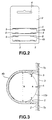
- Fig. 2 is a front view of the blister cover;
- Fig. 3 is a vertical cross sectional view of an essential portion of the blister pack;
- Fig. 4 is a rear view of the blister pack in a state in which a portion of a mount has been separated; and
- Fig. 5 is a perspective view of another embodiment of the blister pack structured to be capable of accommodating two cylindrical batteries.
-
- Embodiments of a battery package according to the present invention will now be described with reference to the drawings. The battery package according to this embodiment is a
blister pack 1 structured to be capable of accommodating two cylindrical batteries. - As shown in Fig. 1, the
blister pack 1 incorporates ablister cover 2; and amount 3 which is bonded to either principal plane (hereinafter simply called as a "rear surface") of theblister cover 2. Theblister pack 1 accommodates twocylindrical batteries cylindrical batteries cylindrical batteries - The
blister cover 2 is constituted by synthetic resin, such as polyethylene terephthalate (PET). As shown in Figs. 1 and 2, theblister cover 2 hasbattery accommodating portions battery accommodating portions blister cover 2 such that the battery accommodating portions 4 project outwards. - As shown in Figs. 1 and 3, each of the battery accommodating portions 4 is a recess opened in the rear surface of the
blister cover 2. The inner diameter of each of the battery accommodating portions 4 is substantially the same as the diameter B of the cylindrical battery 10 which must be accommodated. The surface of the battery accommodating portions 4, which is the projecting principal plane (hereinafter simply called a "surface") of theblister cover 2, is formed into a barrel shape having a circular-arc shape cross section to conform to the shape of the cylindrical battery 10 which must be accommodated. The battery accommodatingportions battery accommodating portions blister cover 2. - The battery accommodating portions 4 has two pairs of
projections 5, that is, fourprojections 5 formed adjacent to the ends of the openings of theblister cover 2 at positions opposite to each other. The distance A between theprojections 5 is shorter than the diameter B of the cylindrical battery 10. The leading end of theprojection 5 is formed to be brought into contact with the outer surface of the accommodated cylindrical battery 10. - As shown in Fig. 3, the battery accommodating portion 4 incorporates the
projections 5 formed more adjacent to the ends of the opening as compared with the center of the cylindrical battery 10 which must be accommodated. Theprojections 5 reduce a portion of the inner diameter of the battery accommodating portion 4 to be smaller than the diameter B of theblister pack 1. The leading ends of theprojections 5 are brought into contact with the cylindrical battery 10. Thus, the accommodated cylindrical battery 10 is held such that the cylindrical battery 10 is pressed against the surface of the battery accommodating portion 4. Therefore, the cylindrical battery 10 accommodated in the battery accommodating portion 4 cannot easily be separated even if the opening is not sealed by themount 3, that is, if theblister pack 1 is opened. Since the cylindrical battery 10 is pressed and held along the surface of the battery accommodating portion 4 of theblister pack 1, rotation of the cylindrical battery 10 accommodated in the battery accommodating portion 4 such that the type and manufacturer can be confirmed can be prevented. The number of theprojections 5 which are formed in the battery accommodating portions 4 of theblister pack 1 is not limited. - The depth of the recessed battery accommodating portion 4 formed in the
blister cover 2 is made to be somewhat larger than the diameter B of the cylindrical battery 10. Therefore, a clearance C is created between the cylindrical battery 10 and themount 3 after themount 3 has been bonded to theblister cover 2 as described later. Thus, no load is exerted from the cylindrical battery 10 accommodated in the battery accommodating portion 4 on themount 3. Hence it follows that the separation of themount 3 occurring during, for example, transport can be prevented. - The battery accommodating portions 4 and the
projections 5 of theblister cover 2 are formed by vacuum molding a flat and rectangular PET sheet. - The
blister cover 2 has ahanger hole 6 formed adjacent to the lengthwise-directional end of theblister cover 2, that is, adjacent to the end portion in which the battery accommodating portions 4 are not formed. Thehanger hole 6 of theblister cover 2 is formed to permit penetration of a pin or the like when theblister pack 1 is hung and displayed at the storefront. - The
mount 3 is bonded to the rear surface of theblister cover 2 to seal the battery accommodating portions 4. Themount 3 is constituted by a cardboard or synthetic-resin film made of PET or the like formed into substantially the same shape as the projected plane of theblister cover 2. - As shown in Fig. 1, the
mount 3 has three perforations which are in parallel with each other in the widthwise direction of themount 3. That is, afirst perforations 7a, asecond perforations 7b and athird perforations 7c (hereinafter collectively called "perforations 7" except for a case where each of theperforations mount 3. Thefirst perforations 7a, thesecond perforations 7b and thethird perforations 7c are formed such that thebattery accommodating portion 4a and thebattery accommodating portion 4b are located among the threeperforations blister pack 1 must be structured such that thesecond perforations 7b are located between thebattery accommodating portion 4a and thebattery accommodating portion 4b. - Either principal plane of the
mount 3 serves as a surface which must be bonded to the rear surface of theblister cover 2. The principal plane is coated with a hot-melt adhesive agent. The principal plane of themount 3 which must be bonded to theblister cover 2 may be laminated with a heat-sensitive film. As an alternative to this, another process for enabling bonding of themount 3 to theblister cover 2 may be employed. - A
non-fusible portion 8 is formed between thefirst perforations 7a and thethird perforations 7c of themount 3, thenon-fusible portion 8 being located adjacent to either side end of themount 3. Thenon-fusible portion 8 is not subjected to the process for applying the hot-melt adhesive agent or the laminating process using the heat-sensitive film. Thenon-fusible portion 8 serves as a portion for permitting start of separation of themount 3 from theblister cover 2. - The
mount 3 has ahanger hole 9 at a position corresponding to thehanger hole 6 formed in theblister cover 2. Thehanger hole 9 of themount 3 is formed to permit penetration of a pin or the like when theblister pack 1 is hung and displayed at the storefront. - The rear flat portion of the
blister cover 2 of theblister pack 1 and the bonding surface of themount 3 are laminated to be opposite to each other. Then, heat or pressure is applied through themount 3 so that theblister cover 2 and themount 3 are bonded to each other. - The
blister pack 1 having the above-mentioned structure permits removal of only required cylindrical batteries 10 of the two accommodated cylindrical batteries 10. When onlycylindrical battery 10b is removed from theblister pack 1, thenon-fusible portion 8 formed between thesecond perforations 7b and thethird perforations 7c is pulled. Thus, only themount 3 between thesecond perforations 7b and thethird perforations 7c is separated from theblister cover 2. Therefore, only thebattery accommodating portion 4b is opened, as shown in Fig. 4. Then, pressure is applied from the right side toward the rear side of theblister pack 1, thecylindrical battery 10b is separated from theprojections 5. Thus, thecylindrical battery 10b is removed from thebattery accommodating portion 4b. Since thebattery accommodating portion 4a is not opened, theblister pack 1 is able to easily preserve the non-used battery 10. - The used
cylindrical battery 10b is inwards pushed from the opening formed in the reverse side toward the right side so that thecylindrical battery 10b is held by theprojections 5. Thus, separation of thecylindrical battery 10b can be prevented and re-accommodation of the same in thebattery accommodating portion 4b is permitted. As described above, theblister pack 1 can be used as a container for accommodating used batteries even after the battery accommodating portion 4 has been opened. When the usedcylindrical battery 10b is accommodated in theblister pack 1, the used battery and the non-used battery can easily be distinguished from each other in accordance with presence of themount 3, that is, whether or not the battery accommodating portion 4 has been opened. Therefore, theblister pack 1 is able to prevent unintentional use of the used battery or discard of a non-used battery caused from mixture of the non-used battery and the used battery. - As described above, the
blister pack 1 according to the embodiment has the structure that the two cylindrical batteries 10 are arranged in parallel with each other in the widthwise direction of theblister pack 1 so as to be accommodated. As a matter of course, the battery package according to the present invention is not limited to the above-mentioned structure. The battery package may be structured to accommodate three or more batteries. Ablister pack 20 shown in Fig. 5 may be employed, theblister pack 20 being structured to arrange two cylindrical batteries 10 in parallel with each other in the lengthwise direction to accommodate the two cylindrical batteries 10. Theblister pack 20 is structured and used similarly to theblister pack 1 except for T-shapedperforations 7. - Each of the
blister pack 1 and theblister pack 20 incorporates theperforations 7. Another structure may be employed which is formed such that the overall portion of themount 3 is separated as a substitute for forming theperforations 7. Also in the foregoing case, a plurality of the battery accommodating potions 4 are independently formed to correspond to the batteries which must be accommodated. Therefore, only required batteries can be removed. The battery which is not used is held in the battery accommodating portion 4 without a fear of separation thanks to theprojections 5. As a result, the battery package according to the present invention can be used as a container for accommodating the batteries. - The battery package according to the present invention has the above-mentioned structure. Thus, each battery is accommodated and held in each of the plural battery accommodating portions each of which has the shape structured such that the portion adjacent to the opening is narrowed as compared with the outer diameter of the battery. Hence it follows that only a required battery can be removed and a battery which is not used is as it is accommodated and held in the battery accommodating portion. Moreover, the battery package according to the present invention permits a non-used battery to again be accommodated in the battery accommodating portion. In addition, the battery package can be used as a container even after the battery package has been opened.
- Although the invention has been described in its preferred form and structure with a certain degree of particularity, it is understood that the present disclosure of the preferred form can be changed in the details of construction and in the combination and arrangement of parts without departing from the spirit and the scope of the invention as hereinafter claimed.
Claims (9)
- A battery package comprising:a cover having a plurality of battery accommodating portions which are opened in either principal plane of said cover, each of which accommodates each battery and which are integrally formed with said cover such that said battery accommodating portions project inwards; anda mount bonded to the principal plane of said cover to seal openings of said battery accommodating portions,
wherein each battery accommodating portion has a battery holding portion formed at a position more adjacent to said opening as compared with the center of said accommodated battery and structured to reduce the inner diameter of said battery accommodating portion as compared with the outer diameter of said battery. - A battery package according to claim 1, wherein said battery holding portions are projections each of which is formed adjacent to said opening of said battery accommodating portion and which project inwards.
- A battery package according to claim 1, wherein said mount has perforations formed at least among said plural battery accommodating portions.
- A battery package comprising:a cover having a plurality of battery accommodating portions which are opened in either principal plane of said cover, each of which accommodates each battery and which are integrally formed with said cover such that said battery accommodating portions project inwards; anda mount bonded to the principal plane of said cover to seal openings of said battery accommodating portions,
wherein each battery accommodating portion has a battery holding portion formed at a position more adjacent to said opening as compared with the center of said accommodated battery and structured to reduce the inner diameter of said battery accommodating portion as compared with the outer diameter of said battery, andsaid mount and said cover have holes having substantially the same shapes. - A battery package according to claim 4, wherein said battery holding portions are projections each of which is formed adjacent to said opening of said battery accommodating portion and which project inwards.
- A battery package according to claim 4, wherein said mount has perforations formed at least among said plural battery accommodating portions.
- A battery package comprising:a cover having a plurality of battery accommodating portions which are opened in either principal plane of said cover, each of which accommodates each battery and which are integrally formed with said cover such that said battery accommodating portions project inwards; anda mount bonded to the principal plane of said cover to seal openings of said battery accommodating portions,
wherein each battery accommodating portion is formed to create a space between said mount and said battery when said battery has been accommodated. - A battery package according to claim 7, wherein said battery holding portions are projections each of which is formed adjacent to said opening of said battery accommodating portion and which project inwards.
- A battery package according to claim 7, wherein said mount has perforations formed at least among said plural battery accommodating portions.
Applications Claiming Priority (2)
| Application Number | Priority Date | Filing Date | Title |
|---|---|---|---|
| JP08678299A JP4154794B2 (en) | 1999-03-29 | 1999-03-29 | Battery package |
| JP8678299 | 1999-03-29 |
Publications (2)
| Publication Number | Publication Date |
|---|---|
| EP1043245A2 true EP1043245A2 (en) | 2000-10-11 |
| EP1043245A3 EP1043245A3 (en) | 2001-08-22 |
Family
ID=13896335
Family Applications (1)
| Application Number | Title | Priority Date | Filing Date |
|---|---|---|---|
| EP00106322A Withdrawn EP1043245A3 (en) | 1999-03-29 | 2000-03-23 | Battery package |
Country Status (3)
| Country | Link |
|---|---|
| US (1) | US6427841B2 (en) |
| EP (1) | EP1043245A3 (en) |
| JP (1) | JP4154794B2 (en) |
Cited By (1)
| Publication number | Priority date | Publication date | Assignee | Title |
|---|---|---|---|---|
| WO2022258471A1 (en) * | 2021-06-08 | 2022-12-15 | Henkel Ag & Co. Kgaa | Rim block cage having an outer packaging |
Families Citing this family (55)
| Publication number | Priority date | Publication date | Assignee | Title |
|---|---|---|---|---|
| JP4809997B2 (en) * | 2001-05-11 | 2011-11-09 | Fdk株式会社 | Battery blister case |
| US20020170218A1 (en) * | 2001-05-21 | 2002-11-21 | Stump Randy W. | Display card having reinforced hanger hole |
| US7036664B2 (en) * | 2002-08-20 | 2006-05-02 | Monster Cable Products, Inc. | Method and apparatus for making and locking members for dispensing packaging products |
| JP3889376B2 (en) * | 2003-05-16 | 2007-03-07 | 松下電器産業株式会社 | Battery package and manufacturing method thereof |
| US7000763B2 (en) * | 2003-10-01 | 2006-02-21 | Keeper Corporation | Consumer goods retail sale display package |
| USD499018S1 (en) | 2003-10-07 | 2004-11-30 | Kim J. Dato | Ribbon dispenser |
| US7780009B2 (en) * | 2004-02-27 | 2010-08-24 | Eveready Battery Company, Inc. | Modular battery package |
| JP2006001574A (en) * | 2004-06-16 | 2006-01-05 | Matsushita Electric Ind Co Ltd | Battery package and manufacturing method thereof |
| US20060096886A1 (en) | 2004-11-05 | 2006-05-11 | Morrison David J | Package/container for batteries |
| US7383954B2 (en) | 2004-11-05 | 2008-06-10 | Morrison David J | Storage and display package for batteries |
| JP2006282260A (en) * | 2005-04-04 | 2006-10-19 | Naris Cosmetics Co Ltd | Cosmetic container |
| US7287648B2 (en) | 2005-09-02 | 2007-10-30 | Tools Aviation, Llc | Battery holder and dispenser |
| JP2007068761A (en) * | 2005-09-07 | 2007-03-22 | Pentax Corp | Capsule holding tool |
| US8800758B2 (en) | 2006-11-17 | 2014-08-12 | Apple Inc. | Gift card carriers |
| US9016469B2 (en) | 2006-11-17 | 2015-04-28 | Apple Inc. | Gift card carriers |
| US9875495B2 (en) | 2007-09-04 | 2018-01-23 | Apple Inc. | Method and apparatus for purchasing digital playlists |
| US20090071865A1 (en) * | 2007-09-17 | 2009-03-19 | Fck, Llc. | Battery packaging |
| US8777110B2 (en) * | 2008-03-03 | 2014-07-15 | Apple Inc. | Multi-pack gift card and activation thereof |
| US8640949B2 (en) * | 2008-03-03 | 2014-02-04 | Apple Inc. | Method for assembling and activating a multi-pack package of transaction cards |
| US20090321305A1 (en) * | 2008-06-25 | 2009-12-31 | Watson Tyler T | Compact battery package |
| US20090321304A1 (en) * | 2008-06-25 | 2009-12-31 | Watson Tyler T | Thermoformed battery package |
| US7624859B1 (en) | 2008-06-25 | 2009-12-01 | Eveready Battery Co., Inc. | Self-standing active foot for blister packaging |
| US7624875B1 (en) | 2008-06-25 | 2009-12-01 | Eveready Battery Co., Inc. | Injection molded battery package |
| USD593854S1 (en) | 2008-06-25 | 2009-06-09 | Eveready Battery Company, Inc. | Battery package |
| US8066125B2 (en) * | 2008-06-25 | 2011-11-29 | Eveready Battery Company, Inc. | Compact injection molded battery package |
| US8875886B2 (en) | 2008-08-25 | 2014-11-04 | Apple Inc. | Carrier card arrangement with removable envelope |
| KR100921623B1 (en) * | 2009-03-11 | 2009-10-15 | 이세희 | Battery package |
| US20110005089A1 (en) * | 2009-07-10 | 2011-01-13 | Richard Kevin Sennett | Cover for shaving cartridges |
| JP2011073721A (en) * | 2009-09-30 | 2011-04-14 | Dainippon Printing Co Ltd | Blister pack capable of being re-closed with capacity reduced |
| ES1072775Y (en) * | 2010-07-13 | 2011-01-04 | Latre Jaime Jove | CONTAINER FOR FACIAL MASK |
| US8523078B2 (en) | 2011-01-28 | 2013-09-03 | Apple Inc. | Transaction card with dual scratch and peel label |
| JP2012166819A (en) * | 2011-02-14 | 2012-09-06 | Naris Cosmetics Co Ltd | Blister pack |
| JP5858567B2 (en) * | 2011-07-15 | 2016-02-10 | Fdk株式会社 | Battery package |
| US20130248406A1 (en) * | 2012-03-21 | 2013-09-26 | Multi Packaging Solutions | Tamper evident packaging |
| USD700069S1 (en) | 2012-08-27 | 2014-02-25 | Mildred Polnitz-Baker | Individual perforated medicine packaging |
| US9701449B2 (en) * | 2013-01-29 | 2017-07-11 | Spectrum Brands, Inc. | Blister pack |
| USD734169S1 (en) * | 2013-10-15 | 2015-07-14 | Printpack Illinois, Inc. | Cigar package |
| USD734170S1 (en) * | 2013-10-15 | 2015-07-14 | Printpack Illinois, Inc. | Cigar package |
| US9614205B2 (en) | 2014-05-23 | 2017-04-04 | Schlage Lock Company Llc | Battery retention assembly and method |
| US12150764B2 (en) * | 2015-01-13 | 2024-11-26 | Biomedical Regenerative Gf, Llc | Sterile fluid collection tube package and methods |
| CN105984658A (en) * | 2015-02-16 | 2016-10-05 | 夏普株式会社 | Tray for baling, baling method, baling material for display device, buffering material and display device with base |
| JP6927249B2 (en) * | 2015-07-22 | 2021-08-25 | 大日本印刷株式会社 | Blister pack |
| US10456327B2 (en) * | 2015-08-28 | 2019-10-29 | Craig Robertson | Package for frozen nutrient pill |
| US9930947B2 (en) * | 2015-09-19 | 2018-04-03 | Hot Concepts, LLC | Payment card enclosure system and methods of manufacturing and use |
| CN111114967A (en) * | 2017-05-23 | 2020-05-08 | 吉利 | Bracket placing groove of bracket packaging box |
| USD880288S1 (en) * | 2017-10-13 | 2020-04-07 | Duracell U.S. Operations, Inc. | Battery packaging |
| JP7199696B2 (en) * | 2018-11-01 | 2023-01-06 | 三甲株式会社 | tray |
| PL3932819T3 (en) * | 2020-07-02 | 2023-07-10 | Varta Microbattery Gmbh | Transparent package for energy storage elements |
| USD996203S1 (en) * | 2021-04-28 | 2023-08-22 | Energizer Brands, Llc | Battery package |
| USD996965S1 (en) * | 2021-04-28 | 2023-08-29 | Energizer Brands, Llc | Battery package |
| USD996204S1 (en) * | 2021-04-28 | 2023-08-22 | Energizer Brands, Llc | Battery package |
| USD1074437S1 (en) | 2022-09-19 | 2025-05-13 | Altria Client Services Llc | Insert with base, lid, and cartridges |
| USD1074436S1 (en) | 2022-09-19 | 2025-05-13 | Altria Client Services Llc | Insert with base, lid, and cartridges |
| US12297022B2 (en) * | 2022-09-19 | 2025-05-13 | Altria Client Services Llc | Insert with undercuts |
| USD1076666S1 (en) | 2022-09-19 | 2025-05-27 | Altria Client Services Llc | Re-closeable package |
Family Cites Families (16)
| Publication number | Priority date | Publication date | Assignee | Title |
|---|---|---|---|---|
| US2952353A (en) * | 1958-05-07 | 1960-09-13 | Howard A Rohdin | Package and method of making same |
| US4011949A (en) * | 1975-06-18 | 1977-03-15 | The Lehigh Press, Inc. | Package construction for opening only by a predetermined procedure |
| US4159771A (en) * | 1977-11-22 | 1979-07-03 | Meiji Seika Kabushiki Kaisha | Container having multiple independently unsealable compartments |
| IT8022940V0 (en) | 1980-09-26 | 1980-09-26 | Cipel Italia | TAPE FOR STORAGE, EXPOSURE AND DISTRIBUTION OF BATTERIES. |
| GB2163130A (en) | 1984-08-17 | 1986-02-19 | Burall Brothers Limited | Blister package backing sheet |
| US4723656A (en) * | 1987-06-04 | 1988-02-09 | Duracell Inc. | Battery package with battery condition indicator means |
| US4958731A (en) * | 1989-11-22 | 1990-09-25 | Duracell Inc. | Battery package |
| US5188231A (en) * | 1991-05-31 | 1993-02-23 | Duracell Inc. | Battery package with removable voltage indicator means |
| JP3166123B2 (en) * | 1992-09-09 | 2001-05-14 | フアイソンズ・ピーエルシー | Drug packaging |
| ES1024736Y (en) * | 1993-04-28 | 1994-10-16 | Celaya Emparanza Galdos Sa | IMPROVEMENTS IN AN EXHIBITOR CONTAINER FOR ELECTRIC BATTERIES |
| US5311989A (en) * | 1993-06-25 | 1994-05-17 | Rayovac Corporation | Common blister battery package and display |
| US5325968A (en) * | 1993-07-14 | 1994-07-05 | Mcneil-Ppc, Inc. | Package for holding tablets |
| US5390792A (en) | 1993-10-18 | 1995-02-21 | Ethicon, Inc. | Sterile packaging |
| US5735404A (en) * | 1995-05-11 | 1998-04-07 | Matsushita Electric Industrial Co., Ltd. | Merchandise package and method of manufacturing the same |
| US5820904A (en) * | 1995-06-12 | 1998-10-13 | Sara Lee Corporation | Meat product package and method of forming same |
| EP0844193A1 (en) | 1996-11-25 | 1998-05-27 | Rayovac Corporation | Package |
-
1999
- 1999-03-29 JP JP08678299A patent/JP4154794B2/en not_active Expired - Fee Related
-
2000
- 2000-03-22 US US09/532,783 patent/US6427841B2/en not_active Expired - Fee Related
- 2000-03-23 EP EP00106322A patent/EP1043245A3/en not_active Withdrawn
Non-Patent Citations (1)
| Title |
|---|
| None |
Cited By (1)
| Publication number | Priority date | Publication date | Assignee | Title |
|---|---|---|---|---|
| WO2022258471A1 (en) * | 2021-06-08 | 2022-12-15 | Henkel Ag & Co. Kgaa | Rim block cage having an outer packaging |
Also Published As
| Publication number | Publication date |
|---|---|
| US6427841B2 (en) | 2002-08-06 |
| EP1043245A3 (en) | 2001-08-22 |
| US20010040115A1 (en) | 2001-11-15 |
| JP2000281129A (en) | 2000-10-10 |
| JP4154794B2 (en) | 2008-09-24 |
Similar Documents
| Publication | Publication Date | Title |
|---|---|---|
| US6427841B2 (en) | Battery package | |
| JP3703101B2 (en) | Blister pack | |
| JPH09107026A (en) | Wafer cassette for wafer storage container | |
| US6296389B1 (en) | Easy-to-open packing bag | |
| EP2308773B1 (en) | Containing device | |
| JPH03124580A (en) | Film containing box | |
| TWM570297U (en) | Panel transportation container | |
| JP2022526712A (en) | Blister card retail battery packaging for coin cell batteries | |
| JP2000085842A (en) | Package | |
| WO2001005680A1 (en) | A reusable dispenser for a tape laminate | |
| CN202828344U (en) | Packaging piece and packaging body | |
| JP7069589B2 (en) | Packaging bag | |
| JP2004123111A (en) | Blister packaging container | |
| JP2000128150A (en) | Box for storing and carrying bag of chemical liquid | |
| CN210913250U (en) | Storage box | |
| JP4442856B2 (en) | Battery housing | |
| EP0810605B1 (en) | Disk cartridge case | |
| JPH0639015A (en) | Press-through pack | |
| JPH0139457Y2 (en) | ||
| JP2003170992A (en) | Box for carrying glass base sheet | |
| JP2019189328A (en) | Package | |
| JP2020104906A (en) | Scattering prevention sheet, ptp sheet, and manufacturing method for ptp sheet | |
| JPH0571161U (en) | Package of tablets | |
| AU2015100251A4 (en) | Improvements relating to the provision of protection for blister packages | |
| JP2018002171A (en) | Package |
Legal Events
| Date | Code | Title | Description |
|---|---|---|---|
| PUAI | Public reference made under article 153(3) epc to a published international application that has entered the european phase |
Free format text: ORIGINAL CODE: 0009012 |
|
| AK | Designated contracting states |
Kind code of ref document: A2 Designated state(s): AT BE CH CY DE DK ES FI FR GB GR IE IT LI LU MC NL PT SE |
|
| AX | Request for extension of the european patent |
Free format text: AL;LT;LV;MK;RO;SI |
|
| PUAL | Search report despatched |
Free format text: ORIGINAL CODE: 0009013 |
|
| AK | Designated contracting states |
Kind code of ref document: A3 Designated state(s): AT BE CH CY DE DK ES FI FR GB GR IE IT LI LU MC NL PT SE |
|
| AX | Request for extension of the european patent |
Free format text: AL;LT;LV;MK;RO;SI |
|
| 17P | Request for examination filed |
Effective date: 20020124 |
|
| AKX | Designation fees paid |
Free format text: DE FR GB |
|
| STAA | Information on the status of an ep patent application or granted ep patent |
Free format text: STATUS: THE APPLICATION HAS BEEN WITHDRAWN |
|
| 18W | Application withdrawn |
Withdrawal date: 20021106 |