EP1043228B1 - D-wing deployable solar array - Google Patents
D-wing deployable solar array Download PDFInfo
- Publication number
- EP1043228B1 EP1043228B1 EP00107487A EP00107487A EP1043228B1 EP 1043228 B1 EP1043228 B1 EP 1043228B1 EP 00107487 A EP00107487 A EP 00107487A EP 00107487 A EP00107487 A EP 00107487A EP 1043228 B1 EP1043228 B1 EP 1043228B1
- Authority
- EP
- European Patent Office
- Prior art keywords
- support member
- solar
- panel
- array
- panels
- Prior art date
- Legal status (The legal status is an assumption and is not a legal conclusion. Google has not performed a legal analysis and makes no representation as to the accuracy of the status listed.)
- Expired - Lifetime
Links
Images



Classifications
-
- B—PERFORMING OPERATIONS; TRANSPORTING
- B64—AIRCRAFT; AVIATION; COSMONAUTICS
- B64G—COSMONAUTICS; VEHICLES OR EQUIPMENT THEREFOR
- B64G1/00—Cosmonautic vehicles
- B64G1/22—Parts of, or equipment specially adapted for fitting in or to, cosmonautic vehicles
- B64G1/42—Arrangements or adaptations of power supply systems
- B64G1/44—Arrangements or adaptations of power supply systems using radiation, e.g. deployable solar arrays
- B64G1/443—Photovoltaic cell arrays
-
- B—PERFORMING OPERATIONS; TRANSPORTING
- B64—AIRCRAFT; AVIATION; COSMONAUTICS
- B64G—COSMONAUTICS; VEHICLES OR EQUIPMENT THEREFOR
- B64G1/00—Cosmonautic vehicles
- B64G1/22—Parts of, or equipment specially adapted for fitting in or to, cosmonautic vehicles
- B64G1/222—Parts of, or equipment specially adapted for fitting in or to, cosmonautic vehicles for deploying structures between a stowed and deployed state
- B64G1/2221—Parts of, or equipment specially adapted for fitting in or to, cosmonautic vehicles for deploying structures between a stowed and deployed state characterised by the manner of deployment
- B64G1/2222—Folding
- B64G1/2224—Folding about multiple axes
-
- B—PERFORMING OPERATIONS; TRANSPORTING
- B64—AIRCRAFT; AVIATION; COSMONAUTICS
- B64G—COSMONAUTICS; VEHICLES OR EQUIPMENT THEREFOR
- B64G1/00—Cosmonautic vehicles
- B64G1/22—Parts of, or equipment specially adapted for fitting in or to, cosmonautic vehicles
- B64G1/222—Parts of, or equipment specially adapted for fitting in or to, cosmonautic vehicles for deploying structures between a stowed and deployed state
- B64G1/2228—Parts of, or equipment specially adapted for fitting in or to, cosmonautic vehicles for deploying structures between a stowed and deployed state characterised by the hold-down or release mechanisms
-
- B—PERFORMING OPERATIONS; TRANSPORTING
- B64—AIRCRAFT; AVIATION; COSMONAUTICS
- B64G—COSMONAUTICS; VEHICLES OR EQUIPMENT THEREFOR
- B64G1/00—Cosmonautic vehicles
- B64G1/22—Parts of, or equipment specially adapted for fitting in or to, cosmonautic vehicles
- B64G1/222—Parts of, or equipment specially adapted for fitting in or to, cosmonautic vehicles for deploying structures between a stowed and deployed state
- B64G1/2229—Parts of, or equipment specially adapted for fitting in or to, cosmonautic vehicles for deploying structures between a stowed and deployed state characterised by the deployment actuating mechanism
-
- Y—GENERAL TAGGING OF NEW TECHNOLOGICAL DEVELOPMENTS; GENERAL TAGGING OF CROSS-SECTIONAL TECHNOLOGIES SPANNING OVER SEVERAL SECTIONS OF THE IPC; TECHNICAL SUBJECTS COVERED BY FORMER USPC CROSS-REFERENCE ART COLLECTIONS [XRACs] AND DIGESTS
- Y10—TECHNICAL SUBJECTS COVERED BY FORMER USPC
- Y10S—TECHNICAL SUBJECTS COVERED BY FORMER USPC CROSS-REFERENCE ART COLLECTIONS [XRACs] AND DIGESTS
- Y10S136/00—Batteries: thermoelectric and photoelectric
- Y10S136/291—Applications
- Y10S136/292—Space - satellite
Definitions
- This invention relates to solar arrays and, more particularly, to increasing the power to weight ratio obtained in solar arrays.
- Solar arrays contain large numbers of photovoltaic cells, also called solar cells, that convert energy from incident sunlight into electricity.
- a major application for the array is for spacecraft in which the solar array is used to recharge the spacecraft's DC batteries.
- solar cells are placed on the surface of the array, and are arranged in strings or series of electrical circuits. Those circuits are further connected in parallel to combine the outputs of the solar cells and collectively provide the appropriate levels of current at a sufficient voltage level suitable for charging the spacecraft's batteries.
- position control apparatus on the spacecraft track the sun's position and, by using various means, the solar arrays are kept in a position that maximizes the amount of sunlight received.
- the solar arrays are light weight and are constructed to be deployable.
- a deployable solar array is formed of a number solar panels in a series. The panels are hinged or joined together, and can be folded up alongside one another for stowage aboard the spacecraft and transport into orbit. In orbit, upon command, the series of panels is unfurled for deployment.
- the allowable stowed volume is restricted by the size of the space craft and the launch vehicle.
- Weight is also an important consideration in spacecraft solar array design. The higher the weight of the solar array, the more fuel is required to launch the spacecraft into orbit. The foregoing factors translate to greater launch cost, which is clearly undesirable.
- the solar array's weight efficiency is therefore recognized as an important design factor.
- the weight efficiency is expressed in terms of its power to weight ratio.
- Typical solar arrays have power to weight ratios ranging from about twenty to fifty watts per kilogram. At such low efficiencies, raising spacecraft power levels using extensions of existing solar array designs carries significant weight penalties.
- US-5,496,414 discloses a stowable and deployable concentrator for solar cells which comprises the features of the preamble of claim 1.
- One problem with that concentrator is that rather complex biasing means are used, namely three leaves springs. These springs increase the weight and the dimensions in stowed condition of the arrangement disclosed there.
- the present invention provides a solar panel according to claim 1 and a solar array comprising such solar panels whose moment of inertia and rigidity automatically increases when the array is deployed.
- the array's support structure changes from a relatively flat two dimensional shape and rectangular cross-section, as stowed, to a curved shape and an airplane wing-shaped cross-section, as deployed.
- the change of shape significantly increases the I x-x inertia, the moment of inertia, by several orders of magnitude, and rigidity of the support structure and, hence, the moment of inertia and rigidity of the solar array.
- the support structure is capable of carrying larger numbers of solar cells within the array than with a flat support, permitting generation of greater amounts of electrical power.
- solar arrays of the foregoing design achieve power to weight ratios two to five times greater than that obtained with conventional space qualified solar array designs.
- Solar array 1 contains two arms 3 and 5, also individually referred to as solar array wings, attached on respective opposite sides of a box 7 by appropriate yokes 9 and 11, only one of which is visible in the figure.
- Solar arrays 3 and 5 extend straight out in opposite directions from opposite sides of box 7, as arms, and, ideally, form in a straight line coaxial with one another.
- Each array contains five solar panels 13a through 17a in array 3 and 13b through 17b in array 5.
- the panels include a curved surface, visible in the figure, and a relatively flat underside surface, only partially visible.
- Each panel is joined to an adjacent panel in the arm by hinges 21, later herein more fully described.
- the solar cells are located on the far side of the relatively flat underside surface of each of the members 3 and 5.
- Electrical cables or harnesses extend from a connection in the box 7, through respective yokes 9 and 11 to each of the panels in the array, electrically connecting the solar panels to an electrical connector in box 7.
- the foregoing harness structure and the contents of the box are conventional and are essentially the same as used in all prior solar arrays, the details of which are not necessary to an understanding of the present invention.
- Each of the aforementioned panels contains four 180 degree strain energy hinges, 19a through 19d, each of which is located at a respective one of the panel's four corners, later herein described in greater detail. Additional hinges, such as hinge 21, connect the yoke to the first panel and each panel to the next adjacent panel to mechanically link the panels together into the solar array. For convenience only the hinges connected to one of the solar panels are labeled in this figure.
- each solar panel or solar array vaguely resembles an airplane wing in appearance. That is, the array contains a curved upper surface 4, as seen in panel 15a on the left, and a flat bottom surface 6, seen through a window in surface 4, and in cross section defines a curved D-shaped sector. Those elements are better illustrated in the next figure, Fig. 2 to which reference is made.
- One of the panels 15a is taken as representative of the plurality of panels and is illustrated in the undeployed or stowed condition in an enlarged perspective view in Fig. 2.
- the panel In this condition the panel is flat, with the upper and lower surfaces, which are essentially coextensive in shape and area, pressed against one another.
- External means not illustrated in the figure, are used to hold the panel flat for stowage, as later herein described in greater detail, against the bias force produced by the hinges.
- the panels would not otherwise be or remain flat under zero gravity conditions.
- the panel's upper surface or support 4 is suitably a skeletal structure or framework formed of a thin flexible material defining, as example, four adjacent "picture frames" in structure.
- the bottom surface is also flat and forms one large rectangular picture frame 6, only the edges of which are visible in the figure, illustrated more clearly in Fig. 3.
- That large picture frame 6 is covered by a thin flexible membrane 8, partially visible through one of the four windows in upper surface 4.
- That membrane serves as a support surface for the solar cells 10, only one of which is pictorially illustrated by dash lines, and those solar cells are distributed about the membranes bottom surface in a conventional arrangement, the details of which are not material to an understanding of the present invention.
- strain energy type hinges 19a through 19d are located at each of the four corners of the assembly.
- the panel-to-panel hinges 21a-21d, illustrated generally in Fig. 1, are omitted in the figure.
- the panel frame When deployed, due to the force exerted by hinges 19a-19d, the panel frame changes in shape into the curved configuration better illustrated in Fig. 3 to which reference is made.
- the upper frame member 4 is outwardly bowed and the lower frame member 6 and accompanying membrane 8 remain essentially flat.
- the panel configuration defines a curved sector, which vaguely resembles the cross section of an airplane wing or the capital letter D.
- strain energy hinges 19a-19d shown in fully deployed condition, located on the opposite ends of the rectangular shaped flat frame 6, earlier illustrated in Fig. 2, pushes the opposite ends of frame member 4 toward one another a short distance. Being relatively flexible, that frame member bows outwardly.
- the panel's 180 degree strain energy hinge 19a is illustrated in greater scale in Fig. 4, illustrating the hinge in the undeployed condition; and again in Fig. 5, in which the hinge is shown deployed.
- the hinge comprises a thin flexible rectangular metal tape 22 and associated mounting brackets 24 and 26 at the respective ends.
- bracket 24 is bolted to another section underlying the end of the tape 22, clamping the tape between those two sections.
- the larger square shaped portion of that bracket is bolted to the upper frame member 4 at a location adjacent a corner.
- bracket 26 contains a portion attached to the tape 22, bolted to another like portion, not visible in the figure, just as with the corresponding portion of mounting bracket 24.
- the latter portion also contains a hinged portion 32, illustrated bent over in the figure, which is attached to a corner of lower frame member 6, suitably with screws or adhesive or other conventional means.
- the strain energy hinges also sometimes referred to as tape measure hinges, are of a recognized design. Those who use a metal tape measure are familiar with the metal tape's slightly curved shape, which affords some measure of stiffness along its length and sides. Yet with sufficient applied force the tape resiliently bends over and folds. The tape may be grasped along its length and, with appropriate force, is manually folded over, causing the area about the fold to flex out and flatten. Once that fold is flattened, further folding requires less force. Moreover, when the tape is released, the tape resiliently returns to shape, literally springs back to shape. The tape is both resilient and flexible.
- Hinges of the foregoing type have earlier been used on solar arrays and have been previously used on satellites manufactured by the present assignee for deploying solar arrays.
- the hinges When used on solar arrays the hinges are aligned like hinges on a swinging door, the flat solar panel, in essentially the same manner as panel-to-panel hinges 21 in the present invention, later herein described.
- Strain energy hinges 19 have the advantage of providing low positive torque during deployment, so that the deployment rate is not excessive, while providing much higher torque during the last few degrees of rotation prior to "latch up", straightening out as illustrated in Fig. 5.
- the latched stiffness of that hinge is extremely high, relatively speaking, that is, the force required to flatten or kink a metal tape, permitting bending.
- each panel hinge located at the upper left corner of the various panels, including hinge 19b on panel 3, are illustrated to the left in the figure.
- the hinges are stacked in line. Individually, those hinges appear the same as in Fig. 4.
- the panel-to-panel hinges, 21, shown in the undeployed condition are also stacked in another line, and are oriented at right angles to the panel hinges 19.
- a tie (not illustrated) holds the panels stacked together, restraining the force of strain energy hinges 19 and 21.
- Panel-to-panel hinges 21 are also strain energy hinges. They each contain a metal tape 23, end brackets 25 and 29 for joining the tape to adjacent panels and an over-travel stop 31. In the undeployed condition, the panel-to-panel hinges stores mechanical energy in the bent tape 23, just like the strain-energy hinges earlier described.
- Fig. 7 illustrates a portion of one of the solar arrays of Fig. 1 in perspective and in a larger scale to better illustrate both the configuration of the panel hinges 19 and the panel-to-panel hinges 21 in the deployed condition.
- the yoke 33 includes a surface 35 formed of flexible material, which can be bowed outwardly as illustrated, a triangular shaped flat surface 36, a transition arm 37, strain energy hinge 39, and a root hinge 41, a hinge that connects the solar array wing to the base drive motor.
- the flat shape to the solar panels, such as illustrated earlier in Fig. 2 is accomplished with an external force, manually as part of the packing procedure implemented by the technician.
- the technician can overcome the bias force of the 180 degree strain energy hinges and compress those spring hinges back to their cocked position, while flattening the support panel.
- Each of the separate panels in the array of Fig. 1 is packed by manually folding the panels over one another in an accordion-like zig-zag fashion and pressing them together, whereby the individual panels are flattened down against the opposing biasing force exerted by the 180 degree strain energy hinges and the panels are held in the folded condition against the biasing force of the panel-to-panel strain energy hinges.
- a tie-down referred to above with respect to Fig. 6, or other like restraint is employed.
- the panel-to-panel hinges 21 push the panels away from one another to unfold them in line as illustrated in Fig. 1 while the spring energy hinges 19 push opposite ends of the panel toward one another, causing the frame member to outwardly bow.
- the frame members 3 and 4 are preferably constructed graphite face sheet aluminum honeycomb sandwich material.
- the preferred form of membrane 8 used to cover that frame member 6 is a "drumskin" tensioned Kapton film. That film is pretensioned in both directions in-plane, while it is bonded at elevated temperatures, about 350 degrees F, to a picture frame style frame constructed from graphite facesheet aluminum honeycomb sandwich construction. Upon cooling from that elevated temperature, the "heat shrink” attachment of the membrane to the frame is completed. The resulting pre-stress should be about 33% of yield and 12% of its ultimate breaking point.
- An ideal film for the application is that currently marketed under the brand name "Kapton JP" and is attached to the frame with a 350 degree F curing film adhesive.
- the bottom framework 6 is designed to possess a greater "beam yield” than framework or surface 4 and greater stiffness. When the spring hinge releases its force there is an action and a reaction as well. But the bottom frame 6, formed of aluminum honeycomb material and being of sufficient stiffness, resists the force exerted at the other end of the spring and does not bend.
- the solar cells are formed of semiconductor material and are of conventional structure and assembly. In the past those cells have been formed on a thin pliant flexible film base that forms the support, the solar panel. The same construction is used with the present invention, using membrane 8 as the base for the cells. The construction details of those prior cell supports are not further described, since they are not necessary to the understanding of the present invention and are known to those skilled in that field of endeavor. The interested reader is referred to the technical and patent literature for those details.
- the structural inertia of a body is its cross-section area multiplied by the distance to the centroid raised to the second power.
- the body's inertia increases substantially.
- the 180 degree strain energy hinges 19 transform the moment of inertia of the solar panel from a low moment of inertia in which the panels are held flat to a significantly greater moment of inertia, accomplishing that by squeezing the opposite ends of a panel together to outwardly bow the panel and thereby change the cross-section of the geometric figure formed by the pair of panels.
- the foregoing embodiment mounts the solar cells to the flat side of the panels. As those skilled in the art appreciate, in alternative embodiments it is also possible to mount the solar cells on the curved side of the panel.
Landscapes
- Engineering & Computer Science (AREA)
- Remote Sensing (AREA)
- Aviation & Aerospace Engineering (AREA)
- Life Sciences & Earth Sciences (AREA)
- Sustainable Development (AREA)
- Photovoltaic Devices (AREA)
Description
- This invention relates to solar arrays and, more particularly, to increasing the power to weight ratio obtained in solar arrays.
- Solar arrays contain large numbers of photovoltaic cells, also called solar cells, that convert energy from incident sunlight into electricity. A major application for the array is for spacecraft in which the solar array is used to recharge the spacecraft's DC batteries. On the array, solar cells are placed on the surface of the array, and are arranged in strings or series of electrical circuits. Those circuits are further connected in parallel to combine the outputs of the solar cells and collectively provide the appropriate levels of current at a sufficient voltage level suitable for charging the spacecraft's batteries. To ensure that the solar array receives sunlight, position control apparatus on the spacecraft track the sun's position and, by using various means, the solar arrays are kept in a position that maximizes the amount of sunlight received.
- For spacecraft application, the solar arrays are light weight and are constructed to be deployable. A deployable solar array is formed of a number solar panels in a series. The panels are hinged or joined together, and can be folded up alongside one another for stowage aboard the spacecraft and transport into orbit. In orbit, upon command, the series of panels is unfurled for deployment.
- Existing solar panels are flat in structure or, and generally speaking, are two dimensional. As a consequence, the panels are not very rigid. As greater amounts of electrical power are required for the spacecraft, the length and width of those panels also grows in order to accommodate greater numbers of solar cells. As the size of the array increases, the ability of the relatively thin panels to withstand the mechanical loads required to maintain adequate sun tracking decreases. Larger size panels may bend or warp, even under low gravity conditions in which the panels are essentially weightless. As the size of the array increases its inertia also increases. Although it is possible to add structural members, such as booms, to increase the array's stiffness and maintain the straightness of the array, such a modification invariably increases both the array's launch weight and its stowed volume.
- Typically, the allowable stowed volume is restricted by the size of the space craft and the launch vehicle. Weight is also an important consideration in spacecraft solar array design. The higher the weight of the solar array, the more fuel is required to launch the spacecraft into orbit. The foregoing factors translate to greater launch cost, which is clearly undesirable.
- The solar array's weight efficiency is therefore recognized as an important design factor. For a solar array the weight efficiency is expressed in terms of its power to weight ratio. Typical solar arrays have power to weight ratios ranging from about twenty to fifty watts per kilogram. At such low efficiencies, raising spacecraft power levels using extensions of existing solar array designs carries significant weight penalties.
- US-5,496,414 discloses a stowable and deployable concentrator for solar cells which comprises the features of the preamble of
claim 1. One problem with that concentrator is that rather complex biasing means are used, namely three leaves springs. These springs increase the weight and the dimensions in stowed condition of the arrangement disclosed there. - Therefore, it is an object of the present invention to provide a solar panel and a sollar array comprising solar panels which are optimised with respect to its biasing means, in particular as regards weight, complexity and dimensions in stowed condition.
- In accordance with the foregoing object, the present invention provides a solar panel according to
claim 1 and a solar array comprising such solar panels whose moment of inertia and rigidity automatically increases when the array is deployed. The array's support structure changes from a relatively flat two dimensional shape and rectangular cross-section, as stowed, to a curved shape and an airplane wing-shaped cross-section, as deployed. The change of shape significantly increases the Ix-x inertia, the moment of inertia, by several orders of magnitude, and rigidity of the support structure and, hence, the moment of inertia and rigidity of the solar array. - With increased rigidity, the support structure is capable of carrying larger numbers of solar cells within the array than with a flat support, permitting generation of greater amounts of electrical power. As an advantage, solar arrays of the foregoing design achieve power to weight ratios two to five times greater than that obtained with conventional space qualified solar array designs.
- The foregoing and additional objects and advantages of the invention together with the structure characteristic thereof, which was only briefly summarized in the foregoing passages, becomes more apparent to those skilled in the art upon reading the detailed description of a preferred embodiment of the invention, which follows in this specification, taken together with the illustration thereof presented in the accompanying drawings.
- In the drawings:
- Figure 1 is an isometric illustration of an embodiment of a solar array containing multiple solar panels as deployed in a dual wing solar array assembly;
- Figure 2 is a perspective view of one of the solar panels in the embodiment of Fig. 1, drawn to a larger scale, showing the relatively two-dimensional flat shape of the solar panel and its support as stowed;
- Figure 3 is a perspective view of the solar panel of Fig. 2, shown as deployed in which the panel assumes a relatively three-dimensional flat shape;
- Figure 4 shows a section of the corner of the panel of Fig. 2 in the stowed condition taken at lines 4-4, illustrating in perspective in larger scale one of the 180 degree strain energy hinges used to join the panel sections at the corners of the solar panel of Figs. 2 and 3;
- Figure 5 shows a section of the corner of the panel of Fig. 3 taken at lines 5-5, illustrating in perspective in larger scale the strain energy hinge of Fig. 4, showing the 180 degree strain energy hinge as deployed:
- Figure 6 partially illustrates to larger scale a corner section of the solar array of Fig. 1 as stowed, showing the stacked relationship of the D-panel hinges and the panel-to-panel hinges used to join adjacent panels together in the array;
- Figure 7 is an enlarged partial section view of a portion of the solar array of Fig. 1, illustrating the panel-to-panel hinges as deployed;
- Figure 8 is another enlarged partial section view of a portion of the solar array of Fig. 1, illustrating the space craft connected end of one of the solar arrays as deployed including the array's transition arm;
- Figure 9 is a enlarged partial section view of a portion of the solar array of Fig. 1, illustrating the array's transition arm in the stowed condition; and
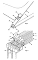
- Figures 10A, 10B and 10C respectively illustrate the changing configuration of the solar array as it is deployed, including, sequentially, the stowed configuration, partially deployed configuration and fully deployed configuration.
-
- Reference is made to Fig. 1, illustrating in perspective the new solar array as deployed.
Solar array 1 contains twoarms box 7 byappropriate yokes Solar arrays box 7, as arms, and, ideally, form in a straight line coaxial with one another. Each array contains fivesolar panels 13a through 17a inarray array 5. The panels include a curved surface, visible in the figure, and a relatively flat underside surface, only partially visible. Each panel is joined to an adjacent panel in the arm byhinges 21, later herein more fully described. - The solar cells, not visible in the figure, are located on the far side of the relatively flat underside surface of each of the
members box 7, throughrespective yokes box 7. The foregoing harness structure and the contents of the box are conventional and are essentially the same as used in all prior solar arrays, the details of which are not necessary to an understanding of the present invention. - Each of the aforementioned panels contains four 180 degree strain energy hinges, 19a through 19d, each of which is located at a respective one of the panel's four corners, later herein described in greater detail. Additional hinges, such as
hinge 21, connect the yoke to the first panel and each panel to the next adjacent panel to mechanically link the panels together into the solar array. For convenience only the hinges connected to one of the solar panels are labeled in this figure. - As deployed, each solar panel or solar array vaguely resembles an airplane wing in appearance. That is, the array contains a curved
upper surface 4, as seen inpanel 15a on the left, and aflat bottom surface 6, seen through a window insurface 4, and in cross section defines a curved D-shaped sector. Those elements are better illustrated in the next figure, Fig. 2 to which reference is made. - One of the
panels 15a is taken as representative of the plurality of panels and is illustrated in the undeployed or stowed condition in an enlarged perspective view in Fig. 2. In this condition the panel is flat, with the upper and lower surfaces, which are essentially coextensive in shape and area, pressed against one another. External means, not illustrated in the figure, are used to hold the panel flat for stowage, as later herein described in greater detail, against the bias force produced by the hinges. As becomes apparent in this description, due to the nature of the panel's construction, the panels would not otherwise be or remain flat under zero gravity conditions. - The panel's upper surface or
support 4 is suitably a skeletal structure or framework formed of a thin flexible material defining, as example, four adjacent "picture frames" in structure. The bottom surface is also flat and forms one largerectangular picture frame 6, only the edges of which are visible in the figure, illustrated more clearly in Fig. 3. Thatlarge picture frame 6 is covered by a thinflexible membrane 8, partially visible through one of the four windows inupper surface 4. That membrane serves as a support surface for thesolar cells 10, only one of which is pictorially illustrated by dash lines, and those solar cells are distributed about the membranes bottom surface in a conventional arrangement, the details of which are not material to an understanding of the present invention. - Continuing with Fig. 2, strain energy type hinges 19a through 19d are located at each of the four corners of the assembly. The panel-to-panel hinges 21a-21d, illustrated generally in Fig. 1, are omitted in the figure.
- When deployed, due to the force exerted by
hinges 19a-19d, the panel frame changes in shape into the curved configuration better illustrated in Fig. 3 to which reference is made. Theupper frame member 4 is outwardly bowed and thelower frame member 6 and accompanyingmembrane 8 remain essentially flat. In cross-section the panel configuration defines a curved sector, which vaguely resembles the cross section of an airplane wing or the capital letter D. In deploying, strain energy hinges 19a-19d, shown in fully deployed condition, located on the opposite ends of the rectangular shapedflat frame 6, earlier illustrated in Fig. 2, pushes the opposite ends offrame member 4 toward one another a short distance. Being relatively flexible, that frame member bows outwardly. - The panel's 180 degree
strain energy hinge 19a is illustrated in greater scale in Fig. 4, illustrating the hinge in the undeployed condition; and again in Fig. 5, in which the hinge is shown deployed. The hinge comprises a thin flexiblerectangular metal tape 22 and associated mountingbrackets bracket 24 is bolted to another section underlying the end of thetape 22, clamping the tape between those two sections. The larger square shaped portion of that bracket is bolted to theupper frame member 4 at a location adjacent a corner. At theother end bracket 26 contains a portion attached to thetape 22, bolted to another like portion, not visible in the figure, just as with the corresponding portion of mountingbracket 24. The latter portion also contains a hingedportion 32, illustrated bent over in the figure, which is attached to a corner oflower frame member 6, suitably with screws or adhesive or other conventional means. - Returning to Fig. 4, when the hinge is in its undeployed condition, it is bent into the U-shaped configuration illustrated, storing force in the formed
spring 22. In this configuration the strain-energy hinge produces a biasing force to unwrap itself from the U-shape and straighten out to the deployed condition as earlier illustrated in Fig. 5. - Returning again to Fig. 5, in order to accommodate
tape 22 when fully straightened as shown, asmall corner portion 28 of theupper frame member 4 is cut away, leaving a clearance space for the tape. The foregoing description of one of the hinges is representative of the other like hinges and associated mounting structure at each of the remaining three corners of the panel frame members, which need not be repeated. - The strain energy hinges, also sometimes referred to as tape measure hinges, are of a recognized design. Those who use a metal tape measure are familiar with the metal tape's slightly curved shape, which affords some measure of stiffness along its length and sides. Yet with sufficient applied force the tape resiliently bends over and folds. The tape may be grasped along its length and, with appropriate force, is manually folded over, causing the area about the fold to flex out and flatten. Once that fold is flattened, further folding requires less force. Moreover, when the tape is released, the tape resiliently returns to shape, literally springs back to shape. The tape is both resilient and flexible.
- Hinges of the foregoing type have earlier been used on solar arrays and have been previously used on satellites manufactured by the present assignee for deploying solar arrays. When used on solar arrays the hinges are aligned like hinges on a swinging door, the flat solar panel, in essentially the same manner as panel-to-panel hinges 21 in the present invention, later herein described.
- Strain energy hinges 19 have the advantage of providing low positive torque during deployment, so that the deployment rate is not excessive, while providing much higher torque during the last few degrees of rotation prior to "latch up", straightening out as illustrated in Fig. 5. The latched stiffness of that hinge is extremely high, relatively speaking, that is, the force required to flatten or kink a metal tape, permitting bending.
- When the solar array assembly of Fig. 1 is placed in the stowed condition, the panels of the
solar arrays box 7 neatly and compactly fold into a small sized package. A portion of one of the corner regions ofsolar panel 3 is illustrated to larger scale as folded in Fig. 6 to which reference is made. - In Fig. 6, each panel hinge located at the upper left corner of the various panels, including
hinge 19b onpanel 3, are illustrated to the left in the figure. The hinges are stacked in line. Individually, those hinges appear the same as in Fig. 4. The panel-to-panel hinges, 21, shown in the undeployed condition, are also stacked in another line, and are oriented at right angles to the panel hinges 19. As shown the individual panels, each formed with the pair ofmembers - Panel-to-panel hinges 21 are also strain energy hinges. They each contain a
metal tape 23,end brackets over-travel stop 31. In the undeployed condition, the panel-to-panel hinges stores mechanical energy in thebent tape 23, just like the strain-energy hinges earlier described. - When the individual solar panels are untied for deployment, such as by the astronaut cutting the above tie as example, the energy in those hinges is released, and the hinge's metal tape thereby straightens out. In so doing the panel-to-panel hinge along the side of a solar panel unfolds a panel from its position facing a side of an adjacent panel and lays it alongside the latter. That action occurs with each of the solar panels. Those solar panels lay alongside one another along a common axis, thereby forming the deployed solar array. This panel-to-panel hinge and its use in tying adjacent panels together in an array is the same as used in the prior flat panel solar array construction. And, simultaneously with the opening of the panel-to-panel hinges 21, the four 180 degree strain energy hinges 19a-19d associated with each panel configure the upper surface of the associated panels into the curved shape earlier described. This final relationship is illustrated with respect to one of the panels in an enlarged view in Fig. 7 to which reference is made.
- Fig. 7 illustrates a portion of one of the solar arrays of Fig. 1 in perspective and in a larger scale to better illustrate both the configuration of the panel hinges 19 and the panel-to-panel hinges 21 in the deployed condition.
- For completeness, the yoke that attaches an end of the solar array to
box 7, earlier illustrated in Fig. 1, is next considered. Reference is made to Fig. 8, partially illustrating an end of the solar array, including the yoke, in perspective as deployed; and to Fig. 9, illustrating the yoke elements of Fig. 8 in perspective in the stowed or undeployed condition. Theyoke 33 includes asurface 35 formed of flexible material, which can be bowed outwardly as illustrated, a triangular shapedflat surface 36, atransition arm 37,strain energy hinge 39, and aroot hinge 41, a hinge that connects the solar array wing to the base drive motor. - As illustrated in Fig. 9,
surface 35 is flattened down in the undeployed condition, by the same means used to flatten down the curved surfaces in the array previously described. That surface andtransition arm 37 are pressed flat against the triangular shapedbottom surface 36, compressingstrain energy hinge 39. In that undeployed condition,surface 35 overlies a portion oftriangular surface 36. When the array is to be deployed the package is untied, removing the restraint fromhinge 39 and hinges 21.Hinge 39 rotatestransition arm 37 upward in the figure and the hinges at the corners ofsurface 35 push the ends of the member inwardly, causingmember 35 to bow outwardly. The latter is the same action described for the solar panels. The yoke thus assumes the deployed condition illustrated in Fig. 8. - The flat shape to the solar panels, such as illustrated earlier in Fig. 2 is accomplished with an external force, manually as part of the packing procedure implemented by the technician. As example, by pressing down on the flexible support panel, the technician can overcome the bias force of the 180 degree strain energy hinges and compress those spring hinges back to their cocked position, while flattening the support panel. Each of the separate panels in the array of Fig. 1 is packed by manually folding the panels over one another in an accordion-like zig-zag fashion and pressing them together, whereby the individual panels are flattened down against the opposing biasing force exerted by the 180 degree strain energy hinges and the panels are held in the folded condition against the biasing force of the panel-to-panel strain energy hinges. To retain the panels in that stowed condition, a tie-down, referred to above with respect to Fig. 6, or other like restraint is employed. When that tie-down is removed to deploy the solar array, the panel-to-panel hinges 21 push the panels away from one another to unfold them in line as illustrated in Fig. 1 while the spring energy hinges 19 push opposite ends of the panel toward one another, causing the frame member to outwardly bow.
- In a practical embodiment of the invention, the
frame members membrane 8 used to cover thatframe member 6 is a "drumskin" tensioned Kapton film. That film is pretensioned in both directions in-plane, while it is bonded at elevated temperatures, about 350 degrees F, to a picture frame style frame constructed from graphite facesheet aluminum honeycomb sandwich construction. Upon cooling from that elevated temperature, the "heat shrink" attachment of the membrane to the frame is completed. The resulting pre-stress should be about 33% of yield and 12% of its ultimate breaking point. An ideal film for the application is that currently marketed under the brand name "Kapton JP" and is attached to the frame with a 350 degree F curing film adhesive. - The
bottom framework 6 is designed to possess a greater "beam yield" than framework orsurface 4 and greater stiffness. When the spring hinge releases its force there is an action and a reaction as well. But thebottom frame 6, formed of aluminum honeycomb material and being of sufficient stiffness, resists the force exerted at the other end of the spring and does not bend. - The solar cells are formed of semiconductor material and are of conventional structure and assembly. In the past those cells have been formed on a thin pliant flexible film base that forms the support, the solar panel. The same construction is used with the present invention, using
membrane 8 as the base for the cells. The construction details of those prior cell supports are not further described, since they are not necessary to the understanding of the present invention and are known to those skilled in that field of endeavor. The interested reader is referred to the technical and patent literature for those details. - The structural inertia of a body is its cross-section area multiplied by the distance to the centroid raised to the second power. In transforming from a flat shape of thin cross section to a larger body of significant greater cross section, such as the D-shape, the body's inertia increases substantially. Essentially the 180 degree strain energy hinges 19 transform the moment of inertia of the solar panel from a low moment of inertia in which the panels are held flat to a significantly greater moment of inertia, accomplishing that by squeezing the opposite ends of a panel together to outwardly bow the panel and thereby change the cross-section of the geometric figure formed by the pair of panels. The tremendous increase in deployed inertia of the membrane's cross section allows the "D-Wing" to behave as a rigged cantilevered wing that, typically, is required to possess a deployed fundamental frequency of anywhere from 0.10 Hz to 0.5 Hz.
- The foregoing embodiment mounts the solar cells to the flat side of the panels. As those skilled in the art appreciate, in alternative embodiments it is also possible to mount the solar cells on the curved side of the panel.
Claims (6)
- A solar panel (13a, ... 17a,; 13b, ... ,17b), comprising:wherein each of said first and second support members (6,4) are rectangular in geometry and contain four corners;a first support member (6) defining a first flat surface;a second support member (4) defining a second flat surface;
said second support member (4) being essentially coextensive in area with said first support member (6) and overlying said first support member (6);
said second support member (4) being flexible In characteristic;
said first support member (6) possessing a stiffness characteristic greater than the corresponding stiffness characteristic of said second support member (4);
biasing means (19a, ... 19d) carried by said first support member (6) for pushing opposite ends of said second support member (4) toward one another to outwardly bow said second support member (4);
characterized in that
said biasing means (19a, ... 19d) comprise four 180 degree strain energy hinges (19a, ... 19d); each of said 180 degree strain energy hinges (19a, ..., 19d) being carried at a respective one of said four comers of said first support member (6) and being connected to a corresponding one of said corners of said second support member (4). - The solar panel according to claim 1, comprising:releaseable restraining means for pressing said second support member (4) against said first support member (6) against said pushing of said biasing means (19a, ..., 19d) to eliminate said bow of said second support member (4).
- The solar panel according to claim 1 or 2, comprising:a plurality of solar cells (10) disposed on and about one of said first and second support members (6, 4).
- A solar array (3, 5) comprising:a plurality of solar panels (13a, ..., 17a; 13b, ..., 17b) according to one of the claims 1 to 3.
- The solar array (3, 5) according to claim 4, comprising:a plurality of strain energy hinge means (21) for connecting said solar panels (13a, ..., 17a; 13b, ..., 17b) together in a line, said strain energy hinge means (21) permitting said solar panels (13a, ..., 17a; 13b, ..., 17b) to be folded over one another for stowage and for unfolding said solar panels (13a, ..., 17a; 13b, ..., 17b) upon deployment.
- The solar array (3, 5) according to claim 5, comprising:releaseable restraining means for holding each of said plurality of solar panels (13a, ..., 17a; 13b, ..., 17b) folded over one another for storage and for pressing said second support member (4) of each solar panel (13a, ..., 17a; 13b, ..., 17b) against said first support member (6) thereof to restrain the respective biasing means (19a, ..., 19d) associated with said solar panel (13a, ..., 17a; 13b, ..., 17b) and flatten said bow in said second support member (4).
Applications Claiming Priority (2)
| Application Number | Priority Date | Filing Date | Title |
|---|---|---|---|
| US09/287,543 US6147294A (en) | 1999-04-06 | 1999-04-06 | D-wing deployable solar array |
| US287543 | 1999-04-06 |
Publications (3)
| Publication Number | Publication Date |
|---|---|
| EP1043228A2 EP1043228A2 (en) | 2000-10-11 |
| EP1043228A3 EP1043228A3 (en) | 2001-07-18 |
| EP1043228B1 true EP1043228B1 (en) | 2003-12-03 |
Family
ID=23103390
Family Applications (1)
| Application Number | Title | Priority Date | Filing Date |
|---|---|---|---|
| EP00107487A Expired - Lifetime EP1043228B1 (en) | 1999-04-06 | 2000-04-06 | D-wing deployable solar array |
Country Status (5)
| Country | Link |
|---|---|
| US (2) | US6147294A (en) |
| EP (1) | EP1043228B1 (en) |
| DE (1) | DE60006884T2 (en) |
| ES (1) | ES2211407T3 (en) |
| IL (1) | IL135090A (en) |
Cited By (5)
| Publication number | Priority date | Publication date | Assignee | Title |
|---|---|---|---|---|
| US10763569B2 (en) | 2013-09-06 | 2020-09-01 | M.M.A. Design, LLC | Deployable reflectarray antenna structure |
| US10773833B1 (en) | 2011-08-30 | 2020-09-15 | MMA Design, LLC | Panel for use in a deployable and cantilevered solar array structure |
| US10971793B2 (en) | 2015-09-25 | 2021-04-06 | M.M.A. Design, LLC | Deployable structure for use in establishing a reflectarray antenna |
| US11724828B2 (en) | 2019-01-18 | 2023-08-15 | M.M.A. Design, LLC | Deployable system with flexible membrane |
| US11990665B2 (en) | 2021-08-04 | 2024-05-21 | M.M.A. Design, LLC | Multi-direction deployable antenna |
Families Citing this family (56)
| Publication number | Priority date | Publication date | Assignee | Title |
|---|---|---|---|---|
| US6550720B2 (en) * | 1999-07-09 | 2003-04-22 | Aeroastro | Aerobraking orbit transfer vehicle |
| US6784359B2 (en) * | 2002-03-04 | 2004-08-31 | Microsat Systems, Inc. | Apparatus and method for the design and manufacture of foldable integrated device array stiffeners |
| US6637702B1 (en) | 2002-04-24 | 2003-10-28 | Lockheed Martin Corporation | Nested beam deployable solar array |
| FR2846297B1 (en) * | 2002-10-29 | 2005-08-26 | Cit Alcatel | JOINT ASSEMBLY OF SOLAR GENERATOR PANELS AND SPACE VEHICLE |
| FR2846298A1 (en) * | 2002-10-29 | 2004-04-30 | Cit Alcatel | ARTICULATED ASSEMBLY OF SOLAR GENERATOR PANELS AND SPATIAL VEHICLE |
| US20050211828A1 (en) * | 2004-03-09 | 2005-09-29 | Aeroastro, Inc. | Aerodynamic orbit inclination control |
| US20060155405A1 (en) * | 2005-01-11 | 2006-07-13 | Zahner L W Iii | Method of creating a dual curve support structure |
| US7481211B2 (en) * | 2005-04-27 | 2009-01-27 | Quixotic Systems, Inc. | Solar panel mounting structure |
| US8109472B1 (en) * | 2006-03-31 | 2012-02-07 | Composite Technology Development, Inc. | Collapsible structures with adjustable forms |
| US8376282B2 (en) * | 2006-03-31 | 2013-02-19 | Composite Technology Development, Inc. | Collapsible structures |
| US8387921B2 (en) * | 2006-03-31 | 2013-03-05 | Composite Technology Development, Inc. | Self deploying solar array |
| US7806370B2 (en) * | 2006-03-31 | 2010-10-05 | Composite Technology Development, Inc. | Large-scale deployable solar array |
| US8066227B2 (en) * | 2006-03-31 | 2011-11-29 | Composite Technology Development, Inc. | Deployable structures having collapsible structural members |
| US9214892B2 (en) * | 2007-11-21 | 2015-12-15 | Orbital Atk, Inc. | Solar arrays |
| US9352853B2 (en) | 2007-11-21 | 2016-05-31 | Orbital Atk, Inc. | Solar arrays, deployment mechanisms therefor, and related methods |
| US8096848B2 (en) * | 2008-05-22 | 2012-01-17 | John Rey Hollis | Collapsible toy airplane |
| US8242349B2 (en) * | 2008-06-25 | 2012-08-14 | Hamilton Sundstrand Corporation | Planar solar concentrator |
| US9281569B2 (en) | 2009-01-29 | 2016-03-08 | Composite Technology Development, Inc. | Deployable reflector |
| US10370126B1 (en) * | 2009-09-09 | 2019-08-06 | M.M.A. Design, LLC | Solar panel array assembly |
| US8683755B1 (en) * | 2010-01-21 | 2014-04-01 | Deployable Space Systems, Inc. | Directionally controlled elastically deployable roll-out solar array |
| US8814099B1 (en) * | 2010-08-31 | 2014-08-26 | MMA Design, LLC | Deployable morphing modular solar array |
| FR2969579B1 (en) * | 2010-12-23 | 2013-08-16 | Thales Sa | LARGE DEPLOYABLE RIGID STRUCTURES AND METHOD FOR DEPLOYING AND LOCKING SUCH STRUCTURES |
| US9048530B2 (en) | 2011-03-09 | 2015-06-02 | Raytheon Company | Deployable flat panel array |
| EP2758997A4 (en) * | 2011-09-22 | 2015-04-08 | Magna Int Inc | Solar panel assembly |
| US9120583B1 (en) * | 2012-03-01 | 2015-09-01 | Deployable Space Systems, Inc. | Space solar array architecture for ultra-high power applications |
| WO2013184164A1 (en) * | 2012-06-08 | 2013-12-12 | Solopower , Inc. | Roof integrated solar module assembly |
| JP6213806B2 (en) * | 2012-11-28 | 2017-10-18 | 日本電気株式会社 | Curved panel structure |
| US9742348B2 (en) | 2013-09-16 | 2017-08-22 | Brigham Young University | Foldable array of three-dimensional panels including functional electrical components |
| US9512618B2 (en) * | 2013-11-20 | 2016-12-06 | Brigham Young University | Rigidly foldable array of three-dimensional bodies |
| USD755118S1 (en) | 2014-10-08 | 2016-05-03 | Composite Technology Development, Inc. | Trifold solar panel |
| USD755119S1 (en) | 2014-10-08 | 2016-05-03 | Composite Technology Development, Inc. | Trifold solar panel |
| USD751498S1 (en) | 2014-10-08 | 2016-03-15 | Composite Technology Development, Inc. | Trifold solar panel |
| USD754598S1 (en) | 2014-10-08 | 2016-04-26 | Composite Technology Development, Inc. | Trifold solar panel |
| US9004410B1 (en) * | 2014-10-24 | 2015-04-14 | Alliance Spacesystems, Llc | Deployable boom for collecting electromagnetic energy |
| US20160137319A1 (en) * | 2014-10-24 | 2016-05-19 | Solaero Technologies Corp. | Method for releasing a deployable boom |
| US10059471B2 (en) | 2014-10-24 | 2018-08-28 | Solaero Technologies Corp. | Method for releasing a deployable boom |
| US10189583B2 (en) * | 2015-05-13 | 2019-01-29 | Analytical Mechanics Associates, Inc. | Deployable sheet material systems and methods |
| US10737806B2 (en) * | 2015-10-08 | 2020-08-11 | Aerojet Rocketdyne, Inc. | Solar array deployment |
| EP3184438B1 (en) * | 2015-12-21 | 2019-11-27 | Airbus Defence and Space GmbH | Space structure with a hinge assembly |
| RU2619155C1 (en) * | 2016-01-19 | 2017-05-12 | федеральное государственное автономное образовательное учреждение высшего образования "Самарский государственный аэрокосмический университет имени академика С.П. Королева (национальный исследовательский университет)" (СГАУ) | Expandable design of the diffraction optical system with large aperture |
| US10742039B2 (en) * | 2017-01-25 | 2020-08-11 | FSWM Technical Enterprises, Inc. | Barge-based solar/wind/wave energy collection |
| US11159121B2 (en) * | 2017-01-25 | 2021-10-26 | FSWM Technical Enterprises, Inc. | Deployable land-based solar energy collection system |
| US10676217B2 (en) | 2017-11-10 | 2020-06-09 | Spire Global, Inc. | Deployable satellite solar panel hinge mechanism |
| US10811759B2 (en) | 2018-11-13 | 2020-10-20 | Eagle Technology, Llc | Mesh antenna reflector with deployable perimeter |
| WO2020116925A1 (en) * | 2018-12-04 | 2020-06-11 | 이정용 | Battery charging apparatus for moving means |
| US11139549B2 (en) | 2019-01-16 | 2021-10-05 | Eagle Technology, Llc | Compact storable extendible member reflector |
| US10797400B1 (en) | 2019-03-14 | 2020-10-06 | Eagle Technology, Llc | High compaction ratio reflector antenna with offset optics |
| CN111177859B (en) * | 2019-12-09 | 2023-09-12 | 上海航天控制技术研究所 | Dynamics equivalent continuum modeling method for truss antenna |
| US12024317B2 (en) * | 2021-03-24 | 2024-07-02 | Opterus Research and Development, Inc. | Morphing self-stiffening array (MOSSA) and hinge |
| US11936335B2 (en) | 2021-07-30 | 2024-03-19 | Momentus Space Llc | Rollable tape spring solar array |
| US11912440B2 (en) * | 2021-09-01 | 2024-02-27 | Maxar Space Llc | Partially flexible solar array structure |
| KR102725655B1 (en) * | 2021-12-21 | 2024-11-05 | 서울과학기술대학교 산학협력단 | Boom assembly |
| CN114735241A (en) * | 2022-03-25 | 2022-07-12 | 航天科工空间工程发展有限公司 | Sun wing spreading mechanism |
| CN115367150B (en) * | 2022-08-03 | 2024-05-17 | 银河航天(北京)网络技术有限公司 | Scissor type solar wing system |
| DE202023000086U1 (en) | 2023-01-04 | 2023-02-02 | Semen Zaitchik | Photovoltaic system with a special arrangement of solar cells |
| DE102023130425B8 (en) * | 2023-11-03 | 2024-12-19 | Dcubed Gmbh | System for one satellite, carrier plate and satellite |
Family Cites Families (21)
| Publication number | Priority date | Publication date | Assignee | Title |
|---|---|---|---|---|
| US3326497A (en) * | 1964-07-24 | 1967-06-20 | Hoffman Electronics Corp | Solar cell array |
| US3473758A (en) * | 1967-11-09 | 1969-10-21 | Webb James E | Roll-up solar array |
| US3690080A (en) * | 1970-09-21 | 1972-09-12 | Trw Inc | Solar array with self-erecting, self-rigidizing roll-up sheets |
| US3976508A (en) * | 1974-11-01 | 1976-08-24 | Mobil Tyco Solar Energy Corporation | Tubular solar cell devices |
| US4015653A (en) * | 1976-04-08 | 1977-04-05 | General Dynamics Corporation | Panel deployment system |
| FR2486493A1 (en) * | 1980-07-11 | 1982-01-15 | Europ Agence Spatiale | IMPROVEMENTS IN SYSTEMS FOR FOLDING AND STABILIZING SOLAR PANELS |
| JPS58175876A (en) * | 1982-04-08 | 1983-10-15 | Mitsubishi Electric Corp | Solar battery array |
| US4713492A (en) * | 1985-10-21 | 1987-12-15 | Energy Conversion Devices, Inc. | Stowable large area solar power module |
| US4755231A (en) * | 1986-06-13 | 1988-07-05 | Trw Inc. | Flexible solar array cell and substrate therefor |
| FR2636598A1 (en) * | 1988-09-22 | 1990-03-23 | Aerospatiale | ARTICULATED PANEL WITH AUTOMATIC LOCKING IN DEPLOYED POSITION, IN PARTICULAR FOR ARTIFICIAL SATELLITE GENERATOR |
| US5244508A (en) * | 1992-04-02 | 1993-09-14 | The United States Of America As Represented By The Administrator Of The National Aeronautics And Space Administration | Self-deploying photovoltaic power system |
| US5236378A (en) * | 1992-08-04 | 1993-08-17 | Edwin Newman | Storage of photovoltaic arrays on a ship |
| US5433259A (en) * | 1993-11-22 | 1995-07-18 | Carefree/Scott Fetzer Company | Retractable awning with integrated solar cells |
| US5520747A (en) * | 1994-05-02 | 1996-05-28 | Astro Aerospace Corporation | Foldable low concentration solar array |
| US5496414A (en) * | 1994-06-02 | 1996-03-05 | Harvey; T. Jeffrey | Stowable and deployable concentrator for solar cells |
| US5578139A (en) * | 1995-01-03 | 1996-11-26 | Aec-Able Engineering Co., Inc. | Stowable and deployable solar energy concentrator with fresnel lenses |
| US5660644A (en) * | 1995-06-19 | 1997-08-26 | Rockwell International Corporation | Photovoltaic concentrator system |
| US5620529A (en) * | 1995-11-03 | 1997-04-15 | Hughes Electronics | Low disturbance solar array |
| US5833176A (en) * | 1996-11-14 | 1998-11-10 | Hughes Electronics Corporation | Bowed solar array |
| US5885367A (en) * | 1997-03-07 | 1999-03-23 | The United States Of America As Represented By The Secretary Of The Navy | Retractable thin film solar concentrator for spacecraft |
| EP0926068A1 (en) * | 1997-12-24 | 1999-06-30 | Fokker Space B.V. | Solar panel assembly |
-
1999
- 1999-04-06 US US09/287,543 patent/US6147294A/en not_active Expired - Fee Related
-
2000
- 2000-03-15 IL IL13509000A patent/IL135090A/en not_active IP Right Cessation
- 2000-03-23 US US09/533,515 patent/US6437232B1/en not_active Expired - Lifetime
- 2000-04-06 EP EP00107487A patent/EP1043228B1/en not_active Expired - Lifetime
- 2000-04-06 ES ES00107487T patent/ES2211407T3/en not_active Expired - Lifetime
- 2000-04-06 DE DE60006884T patent/DE60006884T2/en not_active Expired - Fee Related
Cited By (8)
| Publication number | Priority date | Publication date | Assignee | Title |
|---|---|---|---|---|
| US10773833B1 (en) | 2011-08-30 | 2020-09-15 | MMA Design, LLC | Panel for use in a deployable and cantilevered solar array structure |
| US10763569B2 (en) | 2013-09-06 | 2020-09-01 | M.M.A. Design, LLC | Deployable reflectarray antenna structure |
| US10826157B2 (en) | 2013-09-06 | 2020-11-03 | MMA Design, LLC | Deployable reflectarray antenna structure |
| US11901605B2 (en) | 2013-09-06 | 2024-02-13 | M.M.A. Design, LLC | Deployable antenna structure |
| US10971793B2 (en) | 2015-09-25 | 2021-04-06 | M.M.A. Design, LLC | Deployable structure for use in establishing a reflectarray antenna |
| US11724828B2 (en) | 2019-01-18 | 2023-08-15 | M.M.A. Design, LLC | Deployable system with flexible membrane |
| US12227310B2 (en) | 2019-01-18 | 2025-02-18 | M.M.A. Design, LLC | Deployable system with flexible membrane |
| US11990665B2 (en) | 2021-08-04 | 2024-05-21 | M.M.A. Design, LLC | Multi-direction deployable antenna |
Also Published As
| Publication number | Publication date |
|---|---|
| US6147294A (en) | 2000-11-14 |
| IL135090A0 (en) | 2001-05-20 |
| US6437232B1 (en) | 2002-08-20 |
| ES2211407T3 (en) | 2004-07-16 |
| EP1043228A2 (en) | 2000-10-11 |
| DE60006884T2 (en) | 2004-05-19 |
| DE60006884D1 (en) | 2004-01-15 |
| IL135090A (en) | 2003-07-06 |
| EP1043228A3 (en) | 2001-07-18 |
Similar Documents
| Publication | Publication Date | Title |
|---|---|---|
| US6147294A (en) | D-wing deployable solar array | |
| US7806370B2 (en) | Large-scale deployable solar array | |
| US8109472B1 (en) | Collapsible structures with adjustable forms | |
| US8387921B2 (en) | Self deploying solar array | |
| US9676501B1 (en) | Space solar array architecture for ultra-high power applications | |
| US8376282B2 (en) | Collapsible structures | |
| US8066227B2 (en) | Deployable structures having collapsible structural members | |
| US6188012B1 (en) | Methods and systems for a solar cell concentrator | |
| US10340843B2 (en) | Solar panel with flexible optical elements | |
| US6423895B1 (en) | Solar array for satellite vehicles | |
| US4282394A (en) | Underwing reflector solar array | |
| US6547190B1 (en) | Application of carbon fiber mesh for space and airborne platform applications | |
| EP1174342A1 (en) | Solar concentrator | |
| GB2375230A (en) | A carrier structure for a solar sail | |
| WO2011006506A1 (en) | Foldable frame supporting electromagnetic radiation collectors | |
| US12040740B2 (en) | Retractable Z-fold flexible blanket solar array | |
| US4384163A (en) | Ultra lightweight folding panel structure | |
| US12334865B2 (en) | Passively deployable solar panel array with truss backing and synchronizing linkages | |
| US20020157326A1 (en) | Panel assembly for space applications, arranged to enable synchronizing the deployment of the panels | |
| CN114735241A (en) | Sun wing spreading mechanism | |
| CN112027118A (en) | A solar cell array structure and deployment method | |
| Ritchie et al. | Multikilowatt solar arrays | |
| ELMS, JR | Advanced low-mass solar array technology | |
| Stanhouse et al. | Conceptual approach study of a 200 watt per kilogram solar array | |
| Kavun et al. | Project analysis of power and mass performance of space solar arrays in the wide power range |
Legal Events
| Date | Code | Title | Description |
|---|---|---|---|
| PUAI | Public reference made under article 153(3) epc to a published international application that has entered the european phase |
Free format text: ORIGINAL CODE: 0009012 |
|
| AK | Designated contracting states |
Kind code of ref document: A2 Designated state(s): DE ES FR GB IT |
|
| AX | Request for extension of the european patent |
Free format text: AL;LT;LV;MK;RO;SI |
|
| PUAL | Search report despatched |
Free format text: ORIGINAL CODE: 0009013 |
|
| AK | Designated contracting states |
Kind code of ref document: A3 Designated state(s): AT BE CH CY DE DK ES FI FR GB GR IE IT LI LU MC NL PT SE |
|
| AX | Request for extension of the european patent |
Free format text: AL;LT;LV;MK;RO;SI |
|
| 17P | Request for examination filed |
Effective date: 20010808 |
|
| AKX | Designation fees paid |
Free format text: DE ES FR GB IT |
|
| 17Q | First examination report despatched |
Effective date: 20030129 |
|
| GRAH | Despatch of communication of intention to grant a patent |
Free format text: ORIGINAL CODE: EPIDOS IGRA |
|
| GRAS | Grant fee paid |
Free format text: ORIGINAL CODE: EPIDOSNIGR3 |
|
| GRAA | (expected) grant |
Free format text: ORIGINAL CODE: 0009210 |
|
| RAP1 | Party data changed (applicant data changed or rights of an application transferred) |
Owner name: NORTHROP GRUMMAN CORPORATION |
|
| AK | Designated contracting states |
Kind code of ref document: B1 Designated state(s): DE ES FR GB IT |
|
| RAP1 | Party data changed (applicant data changed or rights of an application transferred) |
Owner name: NORTHROP GRUMMAN CORPORATION |
|
| REG | Reference to a national code |
Ref country code: GB Ref legal event code: FG4D |
|
| REF | Corresponds to: |
Ref document number: 60006884 Country of ref document: DE Date of ref document: 20040115 Kind code of ref document: P |
|
| PGFP | Annual fee paid to national office [announced via postgrant information from national office to epo] |
Ref country code: GB Payment date: 20040401 Year of fee payment: 5 |
|
| PG25 | Lapsed in a contracting state [announced via postgrant information from national office to epo] |
Ref country code: ES Free format text: LAPSE BECAUSE OF NON-PAYMENT OF DUE FEES Effective date: 20040407 |
|
| REG | Reference to a national code |
Ref country code: ES Ref legal event code: FG2A Ref document number: 2211407 Country of ref document: ES Kind code of ref document: T3 |
|
| ET | Fr: translation filed | ||
| PLBE | No opposition filed within time limit |
Free format text: ORIGINAL CODE: 0009261 |
|
| STAA | Information on the status of an ep patent application or granted ep patent |
Free format text: STATUS: NO OPPOSITION FILED WITHIN TIME LIMIT |
|
| PG25 | Lapsed in a contracting state [announced via postgrant information from national office to epo] |
Ref country code: DE Free format text: LAPSE BECAUSE OF NON-PAYMENT OF DUE FEES Effective date: 20041103 |
|
| 26N | No opposition filed |
Effective date: 20040906 |
|
| PG25 | Lapsed in a contracting state [announced via postgrant information from national office to epo] |
Ref country code: IT Free format text: LAPSE BECAUSE OF NON-PAYMENT OF DUE FEES Effective date: 20050406 Ref country code: GB Free format text: LAPSE BECAUSE OF NON-PAYMENT OF DUE FEES Effective date: 20050406 |
|
| REG | Reference to a national code |
Ref country code: ES Ref legal event code: FD2A Effective date: 20040407 |
|
| GBPC | Gb: european patent ceased through non-payment of renewal fee |
Effective date: 20050406 |
|
| PG25 | Lapsed in a contracting state [announced via postgrant information from national office to epo] |
Ref country code: FR Free format text: LAPSE BECAUSE OF NON-PAYMENT OF DUE FEES Effective date: 20040430 |
|
| REG | Reference to a national code |
Ref country code: FR Ref legal event code: ST Effective date: 20111007 |