EP1043136B1 - Vulcanisation mould for the manufacture of technical rubber products - Google Patents
Vulcanisation mould for the manufacture of technical rubber products Download PDFInfo
- Publication number
- EP1043136B1 EP1043136B1 EP00302521A EP00302521A EP1043136B1 EP 1043136 B1 EP1043136 B1 EP 1043136B1 EP 00302521 A EP00302521 A EP 00302521A EP 00302521 A EP00302521 A EP 00302521A EP 1043136 B1 EP1043136 B1 EP 1043136B1
- Authority
- EP
- European Patent Office
- Prior art keywords
- mould
- lamella
- accordance
- vulcanisation
- wall
- Prior art date
- Legal status (The legal status is an assumption and is not a legal conclusion. Google has not performed a legal analysis and makes no representation as to the accuracy of the status listed.)
- Expired - Lifetime
Links
Images


Classifications
-
- B—PERFORMING OPERATIONS; TRANSPORTING
- B29—WORKING OF PLASTICS; WORKING OF SUBSTANCES IN A PLASTIC STATE IN GENERAL
- B29D—PRODUCING PARTICULAR ARTICLES FROM PLASTICS OR FROM SUBSTANCES IN A PLASTIC STATE
- B29D30/00—Producing pneumatic or solid tyres or parts thereof
- B29D30/06—Pneumatic tyres or parts thereof (e.g. produced by casting, moulding, compression moulding, injection moulding, centrifugal casting)
- B29D30/0601—Vulcanising tyres; Vulcanising presses for tyres
- B29D30/0606—Vulcanising moulds not integral with vulcanising presses
-
- B—PERFORMING OPERATIONS; TRANSPORTING
- B29—WORKING OF PLASTICS; WORKING OF SUBSTANCES IN A PLASTIC STATE IN GENERAL
- B29C—SHAPING OR JOINING OF PLASTICS; SHAPING OF MATERIAL IN A PLASTIC STATE, NOT OTHERWISE PROVIDED FOR; AFTER-TREATMENT OF THE SHAPED PRODUCTS, e.g. REPAIRING
- B29C33/00—Moulds or cores; Details thereof or accessories therefor
- B29C33/10—Moulds or cores; Details thereof or accessories therefor with incorporated venting means
-
- B—PERFORMING OPERATIONS; TRANSPORTING
- B29—WORKING OF PLASTICS; WORKING OF SUBSTANCES IN A PLASTIC STATE IN GENERAL
- B29D—PRODUCING PARTICULAR ARTICLES FROM PLASTICS OR FROM SUBSTANCES IN A PLASTIC STATE
- B29D30/00—Producing pneumatic or solid tyres or parts thereof
- B29D30/06—Pneumatic tyres or parts thereof (e.g. produced by casting, moulding, compression moulding, injection moulding, centrifugal casting)
- B29D30/0601—Vulcanising tyres; Vulcanising presses for tyres
- B29D30/0606—Vulcanising moulds not integral with vulcanising presses
- B29D2030/0607—Constructional features of the moulds
- B29D2030/0613—Means, e.g. sipes or blade-like elements, for forming narrow recesses in the tyres, e.g. cuts or incisions for winter tyres
-
- B—PERFORMING OPERATIONS; TRANSPORTING
- B29—WORKING OF PLASTICS; WORKING OF SUBSTANCES IN A PLASTIC STATE IN GENERAL
- B29D—PRODUCING PARTICULAR ARTICLES FROM PLASTICS OR FROM SUBSTANCES IN A PLASTIC STATE
- B29D30/00—Producing pneumatic or solid tyres or parts thereof
- B29D30/06—Pneumatic tyres or parts thereof (e.g. produced by casting, moulding, compression moulding, injection moulding, centrifugal casting)
- B29D30/0601—Vulcanising tyres; Vulcanising presses for tyres
- B29D30/0606—Vulcanising moulds not integral with vulcanising presses
- B29D2030/0607—Constructional features of the moulds
- B29D2030/0617—Venting devices, e.g. vent plugs or inserts
-
- B—PERFORMING OPERATIONS; TRANSPORTING
- B29—WORKING OF PLASTICS; WORKING OF SUBSTANCES IN A PLASTIC STATE IN GENERAL
- B29K—INDEXING SCHEME ASSOCIATED WITH SUBCLASSES B29B, B29C OR B29D, RELATING TO MOULDING MATERIALS OR TO MATERIALS FOR MOULDS, REINFORCEMENTS, FILLERS OR PREFORMED PARTS, e.g. INSERTS
- B29K2021/00—Use of unspecified rubbers as moulding material
Definitions
- the invention relates to a vulcanisation mould for the manufacture of technical rubber products, in particular for the manufacture of vehicle tyres, comprising a plurality of vent openings which lead from the inner space of the mould to the atmosphere which can be closed during the vulcanisation process by contact with blank material.
- vent openings of which several thousand can be provided in a vulcanisation mould
- the purpose of the vent openings is to ensure a problem-free venting of all regions of the vulcanisation mould provided with tread pattern forming projections and lamellae in order to ensure that the tyre blank can precisely contact the shape-giving tools, i.e. projections and lamellae of the vulcanisation mould, during the inflation and shaping process and that such precise contact against the mould is not prevented by air inclusions.
- vent holes or bores lie in the fact that rubber penetrates into these bores, which normally have a diameter of 0.5 to 2.0 mm, and the shoots which are formed give the finished tyre a brush-like or hedgehog-like appearance.
- valves In order to avoid the undesired shoots, it is known to insert valves into the vent bores which are closed by the approaching surface of the blank and which open again on demoulding.
- the disadvantage of the valves of this kind previously used in tyre vulcanisation moulds lies above all in the fact that they are complicated as a result of their multi-part design and that a spiral spring is required to ensure a defined closing and opening process and must have, as far as possible, the same characteristic for the many valves that are required.
- the extremely small dimensions of these valves make it difficult to ensure practically identical characteristics.
- Another proposal in DE 4341683 provides a mould having an internal surface having air exit channels consisting of a large number of micro channels. Such a construction provides a moulding surface having a granular structure where the micro channels take away air. Such a construction does not give a smooth surface to the finished tread pattern.
- the object of the present invention is to provide a further variant and improvement of a mould vent without movable elements, which is particularly economic to realise and which above all ensures an ideal venting in tyre moulds equipped with a plurality of lamellae.
- lamellae arise with a double function, namely lamellae which, in addition to their actual shape-giving function, also take on the function of the venting of the mould.
- the air compressed during the vulcanisation process by the blank material approaching the mould wall, and thus also the lamellae passes through the slots into the gap between the wall parts of the lamellae and then escapes through the transverse bores provided in the mould material. It is important that the movement of the blank material or rubber material is blocked by the part wall of the lamellae laying opposite to their respective air entry slot and thus that no disturbing shoots can arise.
- venting units can naturally also be provided in the respective mould, in particular in the lamellae-free regions of the mould, with the venting system in accordance with German patent application 199 00 596 preferably being used.
- the lamellae are preferably formed as folded double-wall lamellae, with the folded edge of these double-wall lamellae preferably forming the edge of the lamellae at the inner side of the mould.
- the lamellae which are inserted into the mould receive the correct thickness for the respective purpose of use, with the intermediate wall gap required for the venting being formed by the folding and this gap also fully satisfying its function when the part walls of the lamellae practically lie directly in contact with one another, since in this case also an adequate flow cross-section is always available as a result of the areal nature of the gap.
- vent slits can in particular be provided in lamellae regions in which the lamellae have a small radius of curvature. In these regions it is particularly difficult to ensure complete venting, which frequently leads to a nonuniform appearance of the lamellae slits in the finished tyre, i.e. lamellae slits of different width are visible.
- the intermediate wall gap between the opposite lamella walls formed by folds can be precisely defined in accordance with a preferred embodiment of the invention in such a way that beads are introduced or pressed into the lamella walls, so that each such bead comes into contact with the wall opposite to it and thus the intermediate wall gap can be precisely defined, and indeed with the desired minimum dimensions.
- a plurality of transverse bores is preferably provided in each mould segment which intersect with the double-wall lamellae and extend up to the respective end face of the segment, with the gap between adjacent segment end faces being sufficient for the air discharge.
- transverse bores or in addition to transverse bores, bores can also be used which are introduced from the rear side of the mould or mould segments and which, in the same manner as the transverse bores, intersect the double-wall lamellae and thus form air discharge channels.
- bores which are subsequently introduced can also already be formed during the casting of the mould.
- Figure 1 shows a section, i.e. a segment 1 of a tyre mould having a plurality of webs or projections 2 corresponding to the grooves or channels to be formed in the tyre tread pattern, and also with two corrugated lamellae 3, which extend substantially parallel tc one another, which serve for the formation of fine slits or sipes in the tyre tread pattern and which extend between two spaced apart projections 2.
- These lamellae 3 are let into the material of the mould segment and project beyond the inner wall 10 of the mould, for example by about half their total height.
- Transverse bores 4 formed in the mould segment 1 intersect and/or pass through the part of the lamellae 3 embedded in the mould material.
- venting slits 5 extend, starting from the inner wall 10 of the mould, either upwardly over only a part or fraction of the total height of the lamellae 3, or also up to and into the vicinity of the folded edge.
- the lamellae 3 are formed in this embodiment as folded, double-wall lamellae, with the folded edge 6 forming the end edge of the lamellae, i.e. the exposed edge thereof.
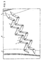
- Figure 3 shows a perspective view of an arrangement of two corrugated lamellae 3 extending between two projections 2, which are formed as folded double-wall lamellae and provided with air discharge slits 5.
- the width of the slits 5 lies in the range from about 0.05 mm to 1 mm, and the height of the slits from the inner wall 10 of the mould onwards lies either in a comparable order of magnitude, or in the region of 1 to 2 mm, or provisions is made for these slits to extend up to and into the vicinity of the folded edge.
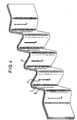
- Figure 4 shows, for the purpose of explanation, a double-wall lamella in accordance with the invention prior to its insertion or integration into the mould.
- the intermediate wall gap 9, which is formed between the two lamella walls 7,8, can be recognised in this illustration; furthermore it can be seen that the slits 5 extend over a substantial part of the total height of the lamellae.
- only the part projection beyond the mould in the wall 10 remains as the actually active vent slit after the integration of the respective lamellae into the mould. Since the lower section of the respective lamellae 3 located in the mould material has transverse bores passing through it, it is always ensured that the air which passes via the slit 5 into the intermediate wall gap 9 can be led away without problems and unhindered.
Landscapes
- Engineering & Computer Science (AREA)
- Mechanical Engineering (AREA)
- Moulds For Moulding Plastics Or The Like (AREA)
- Heating, Cooling, Or Curing Plastics Or The Like In General (AREA)
Abstract
Description
- The invention relates to a vulcanisation mould for the manufacture of technical rubber products, in particular for the manufacture of vehicle tyres, comprising a plurality of vent openings which lead from the inner space of the mould to the atmosphere which can be closed during the vulcanisation process by contact with blank material.
- The purpose of the vent openings, of which several thousand can be provided in a vulcanisation mould, is to ensure a problem-free venting of all regions of the vulcanisation mould provided with tread pattern forming projections and lamellae in order to ensure that the tyre blank can precisely contact the shape-giving tools, i.e. projections and lamellae of the vulcanisation mould, during the inflation and shaping process and that such precise contact against the mould is not prevented by air inclusions.
- An undesired disadvantage of the known vent holes or bores lies in the fact that rubber penetrates into these bores, which normally have a diameter of 0.5 to 2.0 mm, and the shoots which are formed give the finished tyre a brush-like or hedgehog-like appearance.
- In order to avoid the undesired shoots, it is known to insert valves into the vent bores which are closed by the approaching surface of the blank and which open again on demoulding. The disadvantage of the valves of this kind previously used in tyre vulcanisation moulds lies above all in the fact that they are complicated as a result of their multi-part design and that a spiral spring is required to ensure a defined closing and opening process and must have, as far as possible, the same characteristic for the many valves that are required. The extremely small dimensions of these valves make it difficult to ensure practically identical characteristics.
- For the avoidance of these disadvantages it has in particular already been proposed, in the non-prior published German patent application 199 00 596, to mould a respective blocking member in the vent bores which at least substantially blocks the penetration of blank material and which comprises a central body which can be fixed in force-transmitting manner in the respective vent bore as well as a sealing part connected to the central body and having, at the inner side of the mould, a surface region disposed substantially flush with the mould and provided with at least one aperture, with the sealing part forming, together with the mould side end face of the central body, at least one flow path for the air which is pronouncedly angled following the aperture.
- Through this special design of the blocking member it is possible to stop the blank material, which hits the blocking member, without any movable elements, solely on the basis of the guidance of the air flow and to prevent any form of disturbing penetration of blank material into the air discharge passages which are formed, which could lead to shoots on the finished product. This in turn has the consequence that during opening of the mould no rubber material can remain in the specially shaped air discharge passages and block them.
- Another proposal in DE 4341683 provides a mould having an internal surface having air exit channels consisting of a large number of micro channels. Such a construction provides a moulding surface having a granular structure where the micro channels take away air. Such a construction does not give a smooth surface to the finished tread pattern.
- The object of the present invention is to provide a further variant and improvement of a mould vent without movable elements, which is particularly economic to realise and which above all ensures an ideal venting in tyre moulds equipped with a plurality of lamellae.
- According to the present invention this object is satisfied by the mould as set out in Claim 1. Further aspects of the invention are in the subclaims.
- Through this design lamellae arise with a double function, namely lamellae which, in addition to their actual shape-giving function, also take on the function of the venting of the mould. The air compressed during the vulcanisation process by the blank material approaching the mould wall, and thus also the lamellae, passes through the slots into the gap between the wall parts of the lamellae and then escapes through the transverse bores provided in the mould material. It is important that the movement of the blank material or rubber material is blocked by the part wall of the lamellae laying opposite to their respective air entry slot and thus that no disturbing shoots can arise. As a result of the low wall thickness of the part walls of the lamellae, markings which are hardly visible in practice arise at the finished product and no problems arise during demoulding, since no rubber material remains in the slots and thus these very small slots for air discharge always remain free for subsequent vulcanisation processes.
- In addition to the venting via the lamellae, further venting units can naturally also be provided in the respective mould, in particular in the lamellae-free regions of the mould, with the venting system in accordance with German patent application 199 00 596 preferably being used.
- The lamellae are preferably formed as folded double-wall lamellae, with the folded edge of these double-wall lamellae preferably forming the edge of the lamellae at the inner side of the mould. Through the folding process the lamellae which are inserted into the mould receive the correct thickness for the respective purpose of use, with the intermediate wall gap required for the venting being formed by the folding and this gap also fully satisfying its function when the part walls of the lamellae practically lie directly in contact with one another, since in this case also an adequate flow cross-section is always available as a result of the areal nature of the gap.
- Through the folded edge of the double-wall lamellae, the additional advantage arises that sharp-edged transitions are avoided in the finished tyre and rounded transitions can be obtained at the base of the narrow slits. This leads, in particular with blocks of a tread which has many slits, to an improvement, because the danger of notch crack formation at the base as almost completely precluded.
- A further substantial advantage of the invention lies in the fact that vent slits can in particular be provided in lamellae regions in which the lamellae have a small radius of curvature. In these regions it is particularly difficult to ensure complete venting, which frequently leads to a nonuniform appearance of the lamellae slits in the finished tyre, i.e. lamellae slits of different width are visible. Since precisely these critical regions of small radius of curvature can be vented in problem-free manner by appropriate positioning of the vent slits in the lamella walls, a very uniform appearance of the lamella slits in the finished tyre can be achieved through the use of lamellae formed in accordance with the invention, as a result of the full venting of these critical regions which can be achieved.
- The intermediate wall gap between the opposite lamella walls formed by folds can be precisely defined in accordance with a preferred embodiment of the invention in such a way that beads are introduced or pressed into the lamella walls, so that each such bead comes into contact with the wall opposite to it and thus the intermediate wall gap can be precisely defined, and indeed with the desired minimum dimensions.
- A plurality of transverse bores is preferably provided in each mould segment which intersect with the double-wall lamellae and extend up to the respective end face of the segment, with the gap between adjacent segment end faces being sufficient for the air discharge. Instead of transverse bores, or in addition to transverse bores, bores can also be used which are introduced from the rear side of the mould or mould segments and which, in the same manner as the transverse bores, intersect the double-wall lamellae and thus form air discharge channels. Instead of bores which are subsequently introduced, corresponding channels can also already be formed during the casting of the mould.
- Embodiments of the invention will now be described by way of example in conjunction with the following drawings, in which
- Figure 1
- is a perspective illustration of a segment of a tyre mould with lamellae formed in accordance with the invention;
- Figure 2
- is an enlarged representation of the region of the lamellae of the segment of Figure 1;
- Figure 3
- is a detailed view of a region of the lamellae in a mould; and
- Figure 4
- is a perspective illustration of a double-walled lamella prior to its installation or integration into a mould.
- Figure 1 shows a section, i.e. a segment 1 of a tyre mould having a plurality of webs or projections 2 corresponding to the grooves or channels to be formed in the tyre tread pattern, and also with two corrugated lamellae 3, which extend substantially parallel tc one another, which serve for the formation of fine slits or sipes in the tyre tread pattern and which extend between two spaced apart projections 2. These lamellae 3 are let into the material of the mould segment and project beyond the
inner wall 10 of the mould, for example by about half their total height. Transverse bores 4 formed in the mould segment 1 intersect and/or pass through the part of the lamellae 3 embedded in the mould material. - The enlarged representation of Figure 2 enables the design of the fine venting slits 5 in the double-walled lamellae 3 to be seen. These venting slits 5 extend, starting from the
inner wall 10 of the mould, either upwardly over only a part or fraction of the total height of the lamellae 3, or also up to and into the vicinity of the folded edge. - The lamellae 3 are formed in this embodiment as folded, double-wall lamellae, with the folded edge 6 forming the end edge of the lamellae, i.e. the exposed edge thereof. Opposite to the slits 5 formed in each case in one of the two walls of the double-wall lamellae, there is a closed wall region in the other respective wall, so that the rubber material, as a result of the abrupt deflection of the air discharge path, can only enter into the slits 5, but cannot migrate further. Since the material thickness of the walls of the double-wall lamellae 3 is very small, and as a rule does not attain one millimetre, practically no recognisable markings arise at the finished tyre in the region of these slits 3, and never any form of disturbing shoots. During demoulding these very small projections which project into the slits can be removed without problem from the slits, so that these slits always remain free.
- The air which escapes via the slits 5, when blank material approaches the inner wall of the mould, passes via the extremely narrow intermediate space between the two walls of the lamellae 3 to the transverse bores 4 and can escape via these transverse bores 4.
- Figure 3 shows a perspective view of an arrangement of two corrugated lamellae 3 extending between two projections 2, which are formed as folded double-wall lamellae and provided with air discharge slits 5. The width of the slits 5 lies in the range from about 0.05 mm to 1 mm, and the height of the slits from the
inner wall 10 of the mould onwards lies either in a comparable order of magnitude, or in the region of 1 to 2 mm, or provisions is made for these slits to extend up to and into the vicinity of the folded edge. - Figure 4 shows, for the purpose of explanation, a double-wall lamella in accordance with the invention prior to its insertion or integration into the mould. The intermediate wall gap 9, which is formed between the two
lamella walls 7,8, can be recognised in this illustration; furthermore it can be seen that the slits 5 extend over a substantial part of the total height of the lamellae. However, only the part projection beyond the mould in thewall 10 remains as the actually active vent slit after the integration of the respective lamellae into the mould. Since the lower section of the respective lamellae 3 located in the mould material has transverse bores passing through it, it is always ensured that the air which passes via the slit 5 into the intermediate wall gap 9 can be led away without problems and unhindered.
Claims (13)
- A vulcanisation mould for the manufacture of technical rubber products, in particular for the manufacture of vehicle tyres comprising a plurality of vent openings, which lead from the inner space of the mould (1) to the atmosphere which can be closed during the vulcanisation process by contact with blank material, characterised in that at least a part of the vent openings is provided through lamella (3) which are inserted into the mould (1) the lamella (3) being double-walled so as to have an intermediate wall gap (9), and having mutually displaced venting slits (5) in the lamella walls (7,8) at the mould wall side which communicate with the atmosphere via said intermediate wall gap (9) and a bore (4) provided in the mould.
- A vulcanisation mould in accordance with claim 1, characterised in that the venting slits (5) provided in the lamella walls (7,8) are designed in the form of narrow slits which extend, starting from the inner wall (10) of the mould, over a predeterminable distance into the interior space of the mould.
- A vulcanisation mould in accordance with claim 2, characterised in that the width of the slits (5) lies in the range from 0.05 mm to 1 mm, and in that the height of the slits extending into the inner space of the mould is at least 1 to 2 mm.
- A vulcanisation mould in accordance with any of the preceding claims, characterised in that a closed wall region lies opposite to each slit (5) provided in a wall (7,8) of the multi-walled lamella (3).
- A vulcanisation mould in accordance with any of the preceding claims, characterised in that the lamella (3) are formed as folded double-wall lamella.
- A vulcanisation mould in accordance with claim 5, characterised in that the folded edge (6) of the double-wall lamella forms an end edge of the lamella at the inner side of the mould.
- A vulcanisation mould in accordance with any of the preceding claims, characterised in that the width of the double-walled lamella (3) lies approximately in the range from 0.25 mm to 2 mm.
- A vulcanisation mould in accordance with any of the preceding claims, characterised in that each lamella (3) consists of at least two walls which are connected together over a small area.
- A vulcanisation mould in accordance with any of the preceding claims, characterised in that venting slits (5) are disposed in regions of the lamella with a low radius of curvature.
- A vulcanisation mould in accordance with any of the preceding claims, characterised in that the intermediate wall gap (9) of the double-wall lamellae is preset in a defined manner by spacer elements.
- A vulcanisation mould in accordance with claim 10, characterised in that the spacer elements are formed by beads impressed into the walls (7,8).
- A vulcanisation mould in accordance with claim 11, characterised in that the beads are arranged adjacent to the venting slits (5).
- A vulcanisation mould in accordance with any of the preceding claims, characterised in that the bores which intersect the double-wall lamella (3) are introduced at least in part from the rear side of the mould.
Applications Claiming Priority (2)
| Application Number | Priority Date | Filing Date | Title |
|---|---|---|---|
| DE19914215 | 1999-03-29 | ||
| DE19914215A DE19914215A1 (en) | 1999-03-29 | 1999-03-29 | Vulcanization mold with ventilation openings for the production of technical rubber products |
Publications (3)
| Publication Number | Publication Date |
|---|---|
| EP1043136A2 EP1043136A2 (en) | 2000-10-11 |
| EP1043136A3 EP1043136A3 (en) | 2000-11-15 |
| EP1043136B1 true EP1043136B1 (en) | 2004-02-11 |
Family
ID=7902818
Family Applications (1)
| Application Number | Title | Priority Date | Filing Date |
|---|---|---|---|
| EP00302521A Expired - Lifetime EP1043136B1 (en) | 1999-03-29 | 2000-03-28 | Vulcanisation mould for the manufacture of technical rubber products |
Country Status (3)
| Country | Link |
|---|---|
| EP (1) | EP1043136B1 (en) |
| AT (1) | ATE259284T1 (en) |
| DE (2) | DE19914215A1 (en) |
Families Citing this family (6)
| Publication number | Priority date | Publication date | Assignee | Title |
|---|---|---|---|---|
| FR2839003A1 (en) * | 2002-04-29 | 2003-10-31 | Michelin Soc Tech | TIRE MOLD |
| DE102004052766A1 (en) * | 2004-10-30 | 2006-05-04 | Continental Aktiengesellschaft | Tire vulcanizing mold with a plurality of profile segments which can be joined together to form a circumferentially closed mold |
| FR2946915B1 (en) | 2009-06-19 | 2011-06-17 | Michelin Soc Tech | REMOVABLE DEVICE FOR MOLDING A FLEXIBLE WALL IN A PNEUMATIC SCULPTURE SILL |
| FR2983114B1 (en) * | 2011-11-25 | 2013-12-20 | Michelin Soc Tech | MOLD COMPRISING A CAVITY FOR MOLDING A CLOSURE DEVICE IN A GROOVE |
| JP2014151518A (en) * | 2013-02-07 | 2014-08-25 | Sumitomo Rubber Ind Ltd | Mold for tire |
| DE102016222182A1 (en) * | 2016-11-11 | 2018-05-17 | Continental Reifen Deutschland Gmbh | Vulcanization mold and pneumatic vehicle tires |
Family Cites Families (3)
| Publication number | Priority date | Publication date | Assignee | Title |
|---|---|---|---|---|
| DE1965121A1 (en) * | 1969-12-27 | 1971-07-01 | Continental Gummi Werke Ag | Rubber vulcanizing mould with air relief - channels |
| DE4002708A1 (en) * | 1990-01-31 | 1991-08-01 | Herbert Gmbh & Co Maschbau | PROFILE SEGMENT FOR A TIRE VOLCANIZING FORM |
| DE4341683A1 (en) * | 1993-12-07 | 1995-06-08 | Sp Reifenwerke Gmbh | Mould segment for tyre manufacture |
-
1999
- 1999-03-29 DE DE19914215A patent/DE19914215A1/en not_active Withdrawn
-
2000
- 2000-03-28 AT AT00302521T patent/ATE259284T1/en not_active IP Right Cessation
- 2000-03-28 EP EP00302521A patent/EP1043136B1/en not_active Expired - Lifetime
- 2000-03-28 DE DE60008156T patent/DE60008156T2/en not_active Expired - Fee Related
Also Published As
| Publication number | Publication date |
|---|---|
| EP1043136A2 (en) | 2000-10-11 |
| EP1043136A3 (en) | 2000-11-15 |
| DE19914215A1 (en) | 2000-10-05 |
| ATE259284T1 (en) | 2004-02-15 |
| DE60008156T2 (en) | 2004-12-30 |
| DE60008156D1 (en) | 2004-03-18 |
Similar Documents
| Publication | Publication Date | Title |
|---|---|---|
| US8123508B2 (en) | Venting valve to be used in venting bores of vulcanization molds | |
| JP3490876B2 (en) | Vent hole opening / closing valve device for molding dies | |
| US6416304B1 (en) | Mold for molding tire | |
| US7670124B2 (en) | Metal mold for vulcanizing tire treads | |
| US5415826A (en) | Method and device for producing a pneumatic vehicle tire | |
| JP4913944B2 (en) | Tread mold | |
| US20160009004A1 (en) | Air venting valve | |
| US7201570B2 (en) | Tire mold | |
| EP1043136A2 (en) | Vulcanisation mould for the manufacture of technical rubber products | |
| EP1588820A1 (en) | Vented forming mold | |
| KR19980071193A (en) | Tire mold | |
| US20260061778A1 (en) | Undulated tire sipe for improved tire performance and economical mold fabrication | |
| US20260054461A1 (en) | Undulated sipe-molding member for improved tire performance and economical mold fabrication | |
| KR20050084936A (en) | Tire mold and method for making a tire mold | |
| KR101933093B1 (en) | Tire mold | |
| DE102014214841A1 (en) | Vulcanization mold for vulcanizing a pneumatic vehicle tire and pneumatic vehicle tires | |
| EP3321077A1 (en) | Vulcanisation mould and pneumatic tyre for a vehicle | |
| KR20100018529A (en) | Tire mold with vent inlet disposed under mold rib | |
| KR20050044414A (en) | Tyre mould | |
| EP2554349B1 (en) | Mold venting assembly | |
| KR102399491B1 (en) | Exchangeable mold for curing tires | |
| KR102229189B1 (en) | Vent device for tire mold, tire mold assembly and tire manufacturing apparatus comprising the same | |
| WO2017221284A1 (en) | Molding element for manufacturing a noise reducing tread | |
| JPH07329132A (en) | Deformation prevention method when molding instrument panel | |
| EP3356102B1 (en) | Molding element for manufacturing a noise reducing tread |
Legal Events
| Date | Code | Title | Description |
|---|---|---|---|
| PUAI | Public reference made under article 153(3) epc to a published international application that has entered the european phase |
Free format text: ORIGINAL CODE: 0009012 |
|
| PUAL | Search report despatched |
Free format text: ORIGINAL CODE: 0009013 |
|
| AK | Designated contracting states |
Kind code of ref document: A2 Designated state(s): AT BE CH CY DE DK ES FI FR GB GR IE IT LI LU MC NL PT SE |
|
| AX | Request for extension of the european patent |
Free format text: AL;LT;LV;MK;RO;SI |
|
| AK | Designated contracting states |
Kind code of ref document: A3 Designated state(s): AT BE CH CY DE DK ES FI FR GB GR IE IT LI LU MC NL PT SE |
|
| AX | Request for extension of the european patent |
Free format text: AL;LT;LV;MK;RO;SI |
|
| 17P | Request for examination filed |
Effective date: 20010426 |
|
| AKX | Designation fees paid |
Free format text: AT BE CH CY DE DK ES FI FR GB GR IE IT LI LU MC NL PT SE |
|
| 17Q | First examination report despatched |
Effective date: 20020724 |
|
| GRAP | Despatch of communication of intention to grant a patent |
Free format text: ORIGINAL CODE: EPIDOSNIGR1 |
|
| GRAS | Grant fee paid |
Free format text: ORIGINAL CODE: EPIDOSNIGR3 |
|
| GRAA | (expected) grant |
Free format text: ORIGINAL CODE: 0009210 |
|
| RAP1 | Party data changed (applicant data changed or rights of an application transferred) |
Owner name: DUNLOP GMBH & CO. KG |
|
| AK | Designated contracting states |
Kind code of ref document: B1 Designated state(s): AT BE CH CY DE DK ES FI FR GB GR IE IT LI LU MC NL PT SE |
|
| PG25 | Lapsed in a contracting state [announced via postgrant information from national office to epo] |
Ref country code: FI Free format text: LAPSE BECAUSE OF FAILURE TO SUBMIT A TRANSLATION OF THE DESCRIPTION OR TO PAY THE FEE WITHIN THE PRESCRIBED TIME-LIMIT Effective date: 20040211 Ref country code: NL Free format text: LAPSE BECAUSE OF FAILURE TO SUBMIT A TRANSLATION OF THE DESCRIPTION OR TO PAY THE FEE WITHIN THE PRESCRIBED TIME-LIMIT Effective date: 20040211 Ref country code: LI Free format text: LAPSE BECAUSE OF FAILURE TO SUBMIT A TRANSLATION OF THE DESCRIPTION OR TO PAY THE FEE WITHIN THE PRESCRIBED TIME-LIMIT Effective date: 20040211 Ref country code: CH Free format text: LAPSE BECAUSE OF FAILURE TO SUBMIT A TRANSLATION OF THE DESCRIPTION OR TO PAY THE FEE WITHIN THE PRESCRIBED TIME-LIMIT Effective date: 20040211 Ref country code: BE Free format text: LAPSE BECAUSE OF FAILURE TO SUBMIT A TRANSLATION OF THE DESCRIPTION OR TO PAY THE FEE WITHIN THE PRESCRIBED TIME-LIMIT Effective date: 20040211 Ref country code: AT Free format text: LAPSE BECAUSE OF FAILURE TO SUBMIT A TRANSLATION OF THE DESCRIPTION OR TO PAY THE FEE WITHIN THE PRESCRIBED TIME-LIMIT Effective date: 20040211 Ref country code: CY Free format text: LAPSE BECAUSE OF FAILURE TO SUBMIT A TRANSLATION OF THE DESCRIPTION OR TO PAY THE FEE WITHIN THE PRESCRIBED TIME-LIMIT Effective date: 20040211 |
|
| REG | Reference to a national code |
Ref country code: GB Ref legal event code: FG4D |
|
| REG | Reference to a national code |
Ref country code: CH Ref legal event code: EP |
|
| REG | Reference to a national code |
Ref country code: IE Ref legal event code: FG4D |
|
| REF | Corresponds to: |
Ref document number: 60008156 Country of ref document: DE Date of ref document: 20040318 Kind code of ref document: P |
|
| PG25 | Lapsed in a contracting state [announced via postgrant information from national office to epo] |
Ref country code: LU Free format text: LAPSE BECAUSE OF NON-PAYMENT OF DUE FEES Effective date: 20040328 |
|
| PG25 | Lapsed in a contracting state [announced via postgrant information from national office to epo] |
Ref country code: IE Free format text: LAPSE BECAUSE OF NON-PAYMENT OF DUE FEES Effective date: 20040329 |
|
| PG25 | Lapsed in a contracting state [announced via postgrant information from national office to epo] |
Ref country code: MC Free format text: LAPSE BECAUSE OF NON-PAYMENT OF DUE FEES Effective date: 20040331 |
|
| PG25 | Lapsed in a contracting state [announced via postgrant information from national office to epo] |
Ref country code: SE Free format text: LAPSE BECAUSE OF FAILURE TO SUBMIT A TRANSLATION OF THE DESCRIPTION OR TO PAY THE FEE WITHIN THE PRESCRIBED TIME-LIMIT Effective date: 20040511 Ref country code: GR Free format text: LAPSE BECAUSE OF FAILURE TO SUBMIT A TRANSLATION OF THE DESCRIPTION OR TO PAY THE FEE WITHIN THE PRESCRIBED TIME-LIMIT Effective date: 20040511 Ref country code: DK Free format text: LAPSE BECAUSE OF FAILURE TO SUBMIT A TRANSLATION OF THE DESCRIPTION OR TO PAY THE FEE WITHIN THE PRESCRIBED TIME-LIMIT Effective date: 20040511 |
|
| PG25 | Lapsed in a contracting state [announced via postgrant information from national office to epo] |
Ref country code: ES Free format text: LAPSE BECAUSE OF FAILURE TO SUBMIT A TRANSLATION OF THE DESCRIPTION OR TO PAY THE FEE WITHIN THE PRESCRIBED TIME-LIMIT Effective date: 20040522 |
|
| NLV1 | Nl: lapsed or annulled due to failure to fulfill the requirements of art. 29p and 29m of the patents act | ||
| REG | Reference to a national code |
Ref country code: CH Ref legal event code: PL |
|
| ET | Fr: translation filed | ||
| PLBE | No opposition filed within time limit |
Free format text: ORIGINAL CODE: 0009261 |
|
| STAA | Information on the status of an ep patent application or granted ep patent |
Free format text: STATUS: NO OPPOSITION FILED WITHIN TIME LIMIT |
|
| PGFP | Annual fee paid to national office [announced via postgrant information from national office to epo] |
Ref country code: FR Payment date: 20050124 Year of fee payment: 6 |
|
| REG | Reference to a national code |
Ref country code: IE Ref legal event code: MM4A |
|
| 26N | No opposition filed |
Effective date: 20041112 |
|
| PGFP | Annual fee paid to national office [announced via postgrant information from national office to epo] |
Ref country code: DE Payment date: 20060330 Year of fee payment: 7 |
|
| GBPC | Gb: european patent ceased through non-payment of renewal fee |
Effective date: 20070328 |
|
| PG25 | Lapsed in a contracting state [announced via postgrant information from national office to epo] |
Ref country code: PT Free format text: LAPSE BECAUSE OF NON-PAYMENT OF DUE FEES Effective date: 20040711 |
|
| REG | Reference to a national code |
Ref country code: FR Ref legal event code: ST Effective date: 20071130 |
|
| PG25 | Lapsed in a contracting state [announced via postgrant information from national office to epo] |
Ref country code: DE Free format text: LAPSE BECAUSE OF NON-PAYMENT OF DUE FEES Effective date: 20071002 |
|
| PG25 | Lapsed in a contracting state [announced via postgrant information from national office to epo] |
Ref country code: GB Free format text: LAPSE BECAUSE OF NON-PAYMENT OF DUE FEES Effective date: 20070328 |
|
| PGFP | Annual fee paid to national office [announced via postgrant information from national office to epo] |
Ref country code: IT Payment date: 20080322 Year of fee payment: 9 |
|
| PG25 | Lapsed in a contracting state [announced via postgrant information from national office to epo] |
Ref country code: FR Free format text: LAPSE BECAUSE OF NON-PAYMENT OF DUE FEES Effective date: 20070402 |
|
| PG25 | Lapsed in a contracting state [announced via postgrant information from national office to epo] |
Ref country code: FR Free format text: LAPSE BECAUSE OF NON-PAYMENT OF DUE FEES Effective date: 20060331 |
|
| PGFP | Annual fee paid to national office [announced via postgrant information from national office to epo] |
Ref country code: GB Payment date: 20060206 Year of fee payment: 7 |
|
| PG25 | Lapsed in a contracting state [announced via postgrant information from national office to epo] |
Ref country code: IT Free format text: LAPSE BECAUSE OF NON-PAYMENT OF DUE FEES Effective date: 20090328 |