EP1042546B1 - Fiber individualizer - Google Patents
Fiber individualizer Download PDFInfo
- Publication number
- EP1042546B1 EP1042546B1 EP98957051A EP98957051A EP1042546B1 EP 1042546 B1 EP1042546 B1 EP 1042546B1 EP 98957051 A EP98957051 A EP 98957051A EP 98957051 A EP98957051 A EP 98957051A EP 1042546 B1 EP1042546 B1 EP 1042546B1
- Authority
- EP
- European Patent Office
- Prior art keywords
- fibers
- pinch rollers
- stage
- apron belts
- feed stream
- Prior art date
- Legal status (The legal status is an assumption and is not a legal conclusion. Google has not performed a legal analysis and makes no representation as to the accuracy of the status listed.)
- Expired - Lifetime
Links
- 239000000835 fiber Substances 0.000 title claims description 256
- 210000002268 wool Anatomy 0.000 claims description 18
- 238000000034 method Methods 0.000 claims description 16
- 230000000704 physical effect Effects 0.000 claims description 6
- 230000003247 decreasing effect Effects 0.000 claims description 2
- 239000013536 elastomeric material Substances 0.000 description 6
- 238000005259 measurement Methods 0.000 description 6
- 239000000463 material Substances 0.000 description 5
- 229910001220 stainless steel Inorganic materials 0.000 description 5
- 239000010935 stainless steel Substances 0.000 description 5
- 230000000717 retained effect Effects 0.000 description 4
- 230000001133 acceleration Effects 0.000 description 3
- 238000004891 communication Methods 0.000 description 3
- 230000007246 mechanism Effects 0.000 description 3
- 238000013461 design Methods 0.000 description 2
- 230000036961 partial effect Effects 0.000 description 2
- 238000012545 processing Methods 0.000 description 2
- 229920000742 Cotton Polymers 0.000 description 1
- 238000010586 diagram Methods 0.000 description 1
- 230000000694 effects Effects 0.000 description 1
- 239000002657 fibrous material Substances 0.000 description 1
- 239000011521 glass Substances 0.000 description 1
- 230000000670 limiting effect Effects 0.000 description 1
- 239000002184 metal Substances 0.000 description 1
- -1 or some other smooth Substances 0.000 description 1
- 239000004033 plastic Substances 0.000 description 1
- 230000002829 reductive effect Effects 0.000 description 1
- 239000012858 resilient material Substances 0.000 description 1
- 210000003813 thumb Anatomy 0.000 description 1
Images

Classifications
-
- D—TEXTILES; PAPER
- D01—NATURAL OR MAN-MADE THREADS OR FIBRES; SPINNING
- D01G—PRELIMINARY TREATMENT OF FIBRES, e.g. FOR SPINNING
- D01G99/00—Subject matter not provided for in other groups of this subclass
Definitions
- the present invention relates to fiber processing.
- the present invention relates to a device for individualizing wool fibers without breaking the fibers.
- wool form it is meant that many wool fibers, such as in a toe, are measured at the same time and the properties of the toe are ascribed to the individual fibers. It may be more accurate, at times, to measure the properties of individual wool fibers, rather than to take bulk measurements.
- wool fibers tend to be very difficult to individualize. One reason for this is that wool fibers are comparatively longer than many other fibers. Thus, wool fibers are difficult to handle and are easily broken when individualized. These and other difficulties have caused the wool industry to predominantly use bulk measurements, rather than individual measurements.
- a needle-based device for individualizing fibers from a fibrous mass comprises a plurality of combing elements which sequentially pierce the fiber mat and move within a drafting zone with increasing distance between adjacent combing elements.
- This accelerated pin drafting machine feeds a fiber individualizer.
- This known device may not be best suited to process wool fibers, which are more closely attached to one another. In such case drawing the wool fibers by mean of needles may well have the effect of breaking the wool fibers.
- a first stage having first pinch rollers, receives the feed stream and provides it to a second stage.
- the second stage receives the feed stream from the first stage, and provides a thinned stream to a third stage.
- Second stage apron belts draw the feed stream under tension from the first stage into the second stage.
- Second pinch rollers draw the feed stream under tension from the second stage apron belts and provide the thinned stream to the third stage.
- the third stage receives the thinned stream from the second stage and provides individualized fibers.
- Third stage apron belts draw the thinned stream under tension from the second stage into the third stage.
- Third pinch rollers draw the thinned stream under tension from the third stage apron belts and provide the individualized fibers.
- the first, second, and third pinch rollers act as constant speed stages, in which the fibers are maintained at a constant speed for the entire time during which they are held by these pinch rollers.
- the second and third stage apron belts act as variable speed stages which transport and apply an acceleration force to each fiber, and then accelerate the fiber individually when the fiber's trailing end passes from the immediately preceding pinch roller, and which allow a fiber to further accelerate when the leading end of the fiber is acquired by the next pinch roller.
- fibers between the apron belts may be moving at any one of three different speeds.
- the individualized fibers can be drawn off one at a time to an analyzer, where they are measured for physical characteristics, such as length, color, or strength.
- the present invention allows such measurements to be made on fibers individually, and thus reduces the inaccuracies which may be inherent in making the measurements on the toe in bulk form.
- second platens and third platens are disposed adjacent the second stage apron belts and third stage apron belts respectively.
- the platens provide pressure on the feed stream and thinned stream, and allow the fibers to slip to a controlled degree.
- at least one each of the second platens and third platens is a pressure platen, for adjusting the pressure on the feed stream between the second stage apron belts and the thinned stream between the third stage apron belts.
- Stepper motors drive each of the first, second, and third pinch rollers and the second and third stage apron belts, and a speed control separately controls the rotation rates of each.
- the first pinch rollers rotate at a rate of about 5 rpm
- the second stage apron belts rotate at a rate of about 15 rpm
- the second pinch rollers rotate at a rate of about 30 rpm
- the third stage apron belts rotate at a rate of about 60 rpm
- the third pinch rollers rotate at a rate of between about 300 rpm and about 400 rpm.
- a vacuum nozzle is disposed adjacent the third stage, for drawing individualized fibers from the third stage with a non-turbulent air flow.
- An analyzer receives the individualized fibers from the vacuum nozzle, and detect physical properties of the individualized fibers, such as length.
- the first, second, and third stages and the vacuum nozzle are adjustably mounted to a track, for increasing and decreasing gaps between the first, second, and third stages and the vacuum nozzle.
- First adjustable pressure means adjust the pressure between the first pinch rollers, and prevent the fibers within the feed stream from slipping between the first pinch rollers.
- second adjustable pressure means adjust the pressure between the second pinch rollers, and prevent the fibers within the thinned stream from slipping between the second pinch rollers.
- third adjustable pressure means adjust the pressure between the third pinch rollers and prevent the individualized fibers from slipping between the third pinch rollers.
- the fibers are wool and the feed stream is toe.
- the feed stream is provided to first pinch rollers that are rotating at a given speed.
- the pressure between the first pinch rollers is increased until the fibers of the feed stream do not slip between them.
- the fibers are drawn under tension from the first pinch rollers and between a second upper and a second lower apron belts, which are rotating at a speed greater than the speed of the first pinch rollers.
- the pressure on the fibers between the second stage apron belts is adjusted to allow a controlled degree of slip between the fibers.
- the fibers are drawn under tension from the second stage apron belts to second pinch rollers that are rotating at a speed greater than the speed of the second stage apron belts.
- the pressure between the second pinch rollers is increased until the fibers do not slip between the second pinch rollers.
- the fibers are drawn under tension from the second pinch rollers between a third upper and a third lower apron belts, which are rotating at a speed greater than the speed of the second pinch rollers.
- the pressure on the fibers between the third stage apron belts is adjusted to allow a controlled degree of slip between the fibers.
- the fibers are drawn under tension from the third stage apron belts to third pinch rollers, which are rotating at a speed greater than the speed of the third stage apron belts.
- the pressure between the third pinch rollers is increased until the fibers do not slip between the third pinch rollers.
- the fibers are released from the third pinch rollers as individualized fibers.
- the method described individualizes fibers by drawing them into each successive stage at ever increasing rates of speeds.
- those fibers that are slightly ahead of other fibers in the feed stream or in other words, those fibers that enter each set of rollers or belts prior to other fibers in the feed stream, are drawn ahead of the fibers behind it.
- the feed stream is quickly drawn and thinned to the point that individualized fibers are produced.
- Fig. 1 Shown in Fig. 1 is an individualizer 50 for individualizing fibers contained within a feed stream 9 without breaking the fibers.
- the feed stream 9 is a toe of wool, but it could also be a sliver of cotton or some other fibrous material.
- the fibers of the feed stream 9 are substantially parallel within the feed stream 9, but are not aligned as to where they begin or end within the feed stream 9. In other words, the fibers overlap one another along their length within the feed stream 9, such that the feed stream 9 is a long cord of unwoven fibers. Further, the fibers of the feed stream 9 are not substantially twisted together, as are the fibers of a rope. Thus, it is primarily the friction between the individual fibers within the feed stream 9 that keeps the feed stream 9 together in a long cord.
- a first stage 10 receives the feed stream 9 into the individualizer 50.
- the first stage 10 has a fixed position.
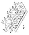
- the first stage 10 is adjustably mounted on a track 52 (depicted in Fig. 2), such that the first stage 10 can be moved and releasably affixed along the length of the track 52. This may be accomplished in any one or more of several different ways.
- the track 52 may comprise one or more straight bars, either square or circular in cross-section, and the first stage 10 has clamps designed to fit around the bars. The clamps are loosened so that the first stage 10 can slide and be adjusted in position along the length of the bars, and then the clamps are tightened to affix the first stage 10 in the desired position.
- the track 52 could be one or more lead screws, with the bearing portions of the lead screws attached to the first stage 10. The lead screws of the track are then rotated to move the first stage 10 forward or backward along the track 52, and the first stage 10 is then held in place by the threads of the lead screws when they are no longer rotated, thus affixing the first stage 10 in place.
- the track 52 may be one or more toothed rails which mesh with gears attached to the first stage 10.
- the gears may be motorized to advance the first stage 10 back and forth along the length of the track 52. The internal resistance of the motors may then keep the first stage 10 in the desired location.
- any combination of these methods may also be used to affix the first stage 10 to the track 52, and many other methods and devices could also be readily adapted, and are within the spirit of this disclosure.
- the first stage 10 includes first pinch rollers 16a and 16b, for drawing the feed stream 9 into the first stage 10.
- first pinch rollers 16a and 16b are rubber and the other is stainless steel.
- both of the first pinch rollers 16a and 16b are either rubber or some other elastomeric material, or stainless steel or some other hard material.
- the first pinch rollers 16a and 16b may be ribbed along their length to provide increased surfaces and edges for friction between the first pinch rollers 16a and 16b and the fibers of the feed stream 9 which pass between them.
- First adjustable pressure means 56a (depicted in Fig. 2) are used to adjust the pressure between the first pinch rollers 16a and 16b.
- the first adjustable pressure means 56a may be provided by one or more of several different mechanisms.
- the ends of the first pinch rollers 16a and 16b may each be mounted to a screw, with one end of the upper first pinch roller 16a at one end of the screw, and the corresponding end of the lower first pinch roller 16b at the other end of the screw, with a similar configuration at the other ends of the first pinch rollers 16a and 16b. In this manner, when the screws are rotated in one direction, the first pinch rollers 16a and 16b are drawn toward one another, and when the screws are rotated in the other direction the first pinch rollers 16a and 16b are pushed apart from each other.
- one of the first pinch rollers 16a and 16b may be placed in an affixed position and the other of the first pinch rollers 16a and 16b may be adjustable toward and away from the affixed roller. This may be accomplished by mounting one of the first pinch rollers 16a and 16b on thumb screws, which can be adjusted to move the first pinch roller 16a or 16b back and forth. Further, pressurized cylinders, either hydraulically or pneumatically powered, may be attached to the movable first pinch roller 16a or 16b, to provide the pressure between the first pinch rollers 16a and 16b. Of course, there are several other devices which may also be employed to provide pressure between the first pinch rollers 16a and 16b, which other devices are contemplated by the invention and are within the scope of this disclosure.
- the materials from which the first pinch rollers 16a and 16b are formed are selected in part on their ability to firmly grasp and provide friction to the fibers of the feed stream 9.
- the adjustable pressure between the first pinch rollers 16a and 16b is also provided, in part, to enhance the ability of the first pinch rollers 16a and 16b to provide friction to the fibers of the feed stream 9.
- the Fibers of the feed stream 9 preferably do not slip between the first pinch rollers 16a and 16b.
- the fibers of the feed stream 9 will preferably retain their position rotative to one another along the length of the feed stream 9 for the entire time that they are engaged between the first pinch rollers 16a and 16b.
- the importance.of retaining the fibers of the feed stream 9 between the first pinch rollers 16a and 16b such that they cannot slip past one another is described in greater detail below.
- the first pinch rollers 16a and 16b arc rotated at the same speed and in opposing directions, so that the feed stream 9 placed between them is drawn between the first pinch rollers 16a and 16b and ejected out from between the first pinch rollers 16a and 16b on the other side.
- a stepper motor 54 (depicted in Fig. 2) provides the rotation for the first pinch rollers 16a and 16b, and a speed control 42 (depicted in Fig. 2), in communication with the stepper motor 54, controls the speed at which the first pinch rollers 16a and 16b rotate.
- the first pinch rollers 16a and 16b rotate at a first given speed, which in the preferred embodiment is about 5 rotations per minute (rpm). The significance of this speed is described in greater detail below.
- a second stage 12 is disposed adjacent the first stage 10, and is also mounted on the track 52 (depicted in Fig. 2) in a manner similar to that described above in great detail for the first stage 10.
- the second stage 12 receives the feed stream 9 from the first stage 10, and provides a thinned stream 13.
- Second stage apron belts 18a and 18b receive the feed stream 9, and draw the feed stream 9 under tension between the second stage apron belts 18a and 18b.
- the second stage apron belts 18a and 18b are preferably an elastomeric material such as rubber, that provides a relatively great degree of friction between the fibers of the feed stream 9 and the second stage apron belts 18a and 18b.
- the second stage apron belts 18a and 18b are preferably tensionally secured about sets 20a and 20b of two or more rollers. In this manner, when any one of the rollers 20a and 20b are rotated, the second stage apron belts 18a and 18b are also rotated.
- the rotational power to the second stage apron belts 18a and 18b is provided by a stepper motor 54 (depicted in Fig. 2).
- the second stage apron belts 18a and 18b are driven in opposing rotational directions, such that the feed stream 9 which is received between them is drawn in between them and ejected out from between them on the other side.
- the directions of rotation are selected to coincide with the directions of rotation of the first pinch rollers 16a and 16b.
- the second upper apron belt 20a and the first upper pinch roller 16a are rotating in a first direction
- the second lower apron belt 20b and the first lower pinch roller 16b are rotating in a second direction.
- the result of this configuration is that the feed stream 9 entering between the first pinch rollers 16a and 16b is urged in one direction along a path between the first pinch rollers 16a and 16b and the second stage apron belts 18a and 18b.
- the speed at which the second stage apron belts 18a and 18b rotate is controlled by the speed control 42 (depicted in Fig. 2), and is independently variable depending on the draft ratio required.
- the rotational speed of the second stage apron belts 18a and 18b is greater than the speed at which the first pinch rollers 16a and 16b rotate, and the significance of this relationship is explained in greater detail below.
- the rotational speed of the second stage apron belts 18a and 18b is about 15 rpm.
- Second platens 22a and 22b are disposed adjacent and on opposing sides of the second stage apron belts 18a and 18b. Because the second stage apron belts 18a and 18b are preferably constructed of an elastomeric material, the second platens 22a and 22b provide some rigidity and resistance to the second stage apron belts 18a and 18b along a distance between the rollers 20a and 20b on which the second stage apron belts 18a and 18b are mounted. This rigidity and resistance helps to enhance the friction between the second stage apron belts 18a and 18b and the feed stream 9 which is drawn between them.
- the platens 22a and 22b are preferably made of metal but could also be made of plastic, glass, or some other smooth, resilient material which has a low coefficient of friction so as to not cause excessive wear to the aprons.
- the pressure between the second stage apron belts 18a and 18b and the fibers of the feed stream 9 is further enhanced by placing a pressure module 24a adjacent one or bath of the second platens 22a and 22b.
- a pressure module 24a is depicted adjacent the second upper platen 22a, which makes the second upper platen 22a a pressure platen.
- the pressure module 24a may be a mechanical, hydraulic, or pneumatic device as described above, and is provided to further enhance and finely control the pressure exerted by the second stage apron belts 18a and 18b on the fibers of the feed stream 9.
- the components of the portion of the second stage 12 described above, being the second stage apron belts 18a and 18b, the rollers 20a and 20b, the platens 22a and 22b, and the pressure module 24a, are designed to allow a controlled degree of slip between the fibers of the feed stream 9.
- the fibers are between the second stage apron belts 18a and 18b, it is intended that some of the fibers are advanced through the second stage apron belts 18a and 18b at a faster rate than others of the fibers in the feed stream 9.
- the feed stream 9 is thinned as it moves between the second stage apron belts 18a and 18b.
- the fibers within the feed stream 9 are partially, but not completely individualized as they move through the second stage 12. This is explained in greater detail below.
- the fibers of the feed stream 9 are received by second pinch rollers 16c and 16d.
- the second pinch rollers 16c and 16d are preferably configured in a manner very similar to the first pinch rollers 16a and 16b.
- one of the second pinch rollers 16c and 16d is preferably rubber and the other is preferably stainless steel.
- both of the second pinch rollers 16c and 16d are either rubber or some other elastomeric material, or stainless steel or some other hard material.
- the second pinch rollers 16c and 16d may be ribbed along their length to provide increased surfaces and edges for friction between the second pinch rollers 16c and 16d and the fibers of the feed stream 9 which pass between them.
- Second adjustable pressure means 56b (depicted in Fig. 2) are used to adjust the pressure between the second pinch rollers 16c and 16d.
- the second adjustable pressure means 56b may be provided by one or more of several different mechanisms as explained above.
- the materials from which the second pinch rollers 16c and 16d are formed are selected in part on their ability to firmly grasp and provide friction to the fibers of the feed stream 9.
- the adjustable pressure between the second pinch rollers 16c and 16d is also provided, in part, to enhance the ability of the second pinch rollers 16c and 16d to provide friction to the fibers of the feed stream 9. In this manner, the fibers of the feed stream 9 preferably do not slip between the second pinch rollers 16c and 16d.
- the second pinch rollers 16c and 16d are rotated at the same speed and in opposing directions, so that the feed stream 9 placed between them is drawn between the second pinch rollers 16c and 16d and ejected out from between the second pinch rollers 16c and 16d on the other side.
- a stepper motor 54 (depicted in Fig. 2) provides the rotation between the second pinch rollers 16c and 16d, and the speed control 42 (depicted in Fig. 2), in communication with the stepper motor 54, independently controls the speed at which the second pinch rollers 16c and 16d rotate.
- the second pinch rollers 16c and 16d rotate at a speed that is greater than the speed at which the second stage apron belts 18a and 18b rotate. In the preferred embodiment, the second pinch rollers 16c and 16d rotate at a speed of about 30 rpm.
- the fibers of the feed stream 9 are accelerated as they move through the first pinch rollers 16a and 16b, the second stage apron belts 18a and 18b, and the second pinch rollers 16c and 16d. This acceleration tends to thin out the feed stream 9 as briefly described above. To continue the explanation of how this is accomplished, as the fibers of the feed stream 9 pass through the first pinch rollers 16a and 16b, the trailing ends of each of the fibers are retainably held between the first pinch rollers 16a and 16b. The leading ends of the fibers, however, are tensionally drawn between the second stage apron belts 18a and 18b.
- the first pinch rollers 16a and 16b because they exert sufficient pressure on the fibers so that they are not released, prevent the fibers from being pulled through the second stage 12 at the faster rate at which the second stage apron belts 18a and 18b are rotating.
- the second stage apron belts 18a and 18b are dragging past the fibers at a greater speed than that at which they are allowed to travel by the first pinch rollers 16a and 16b.
- This is the importance of the pressure between the first pinch rollers 16a and 16b being sufficient to retain the fibers of the feed stream 9: so that the fibers are not dragged from between the first pinch rollers 16a and 16b until the end of the fiber is released from between the first pinch rollers 16a and 16b.
- the pressure between the second stage apron belts 18a and 18b provides a controlled degree of slip between the fibers of the feed stream 9. If the pressure between the second stage apron belts 18a and 18b is too great, it tends to break the fibers which have not yet been released from the first pinch rollers 16a and 16b. If the pressure between the second stage apron belts 18a and 18b is not great enough, then it is insufficient to overcome the friction between the fibers themselves and accelerate the fibers that have been released from the first pinch rollers 16a and 16b past the other fibers of the feed stream 9 that have not yet been released from the first pinch rollers 16a and 16b.
- the fibers may be pulled out by the pressure exerted between the second stage apron belts 18a and 18b, and the fibers will not be thinned in a uniform manner.
- first gap 40 of between about 0,0127 m (one-half inches) and about 0,1143 m (four and one-half inches) betwecn the first stage 10 and the second stage 12.
- the width of this gap 40 is selected based in part on the length of the fibers within the feed stream 9 that are processed through the individualizer 50.
- the first gap 40 is set so that the distance between the first pinch rollers 16a and 16b and the second pinch rollers 16c and 16d is at least just greater than the length of the longest fibers in the feed stream 9.
- both the first pinch rollers 16a and 16b and the second pinch rollers 16c and 16d exert sufficient pressure on the fibers such that the fibers are retainably held by both the first pinch rollers 16a and 16b and the second pinch rollers 16c and 16d.
- the fiber would be broken or stretched by the individualizer 50.
- the second pinch rollers 16c and 16d are rotating at a much greater rate of speed than are the first pinch rollers 16a and 16b.
- the second pinch rollers 16c and 16d would try to pull the fiber faster than the first pinch rollers 16a and 16b could release it. Because the friction between the first pinch rollers 16a and 16b and the second pinch rollers 16c and 16d is great enough so that fibers cannot slip from between them, the fiber would be broken. This would tend to invalidate any subsequent readings taken on the individualized fibers, such as length measurements.
- leading fibers are drawn out ahead of trailing fibers as the fibers exit the first pinch rollers 16a and 16b and enter the second stage apron belts 18a and 18b, so also are leading fibers drawn out ahead of trailing fibers as the fibers enter the second pinch rollers 16c and 16d. Because the second pinch rollers 16c and 16d rotate at a faster speed than do the second stage apron belts 18a and 18b, the second pinch rollers 16c and 16d cause the fibers which are drawn into them to slip past other fibers at a rate of speed that is greater than the speed of the second stage apron belts 18a and 18b and the speed of the first pinch rollers 16a and 16b.
- fibers within the feed stream 9 are moving at three different speeds in the area between the second stage apron belts 18a and 18b.
- the slowest moving fibers are those which are still retained between the first pinch rollers 16a and 16b and which are moving at the same speed as the first pinch rollers 16a and 16b.
- Accelerating past the slowest fibers are those which have been released from the first pinch rollers 16 and 16b and which are moving at the speed of the second stage apron belts 18a and 18b.
- Accelerating past both these slower two groups of fibers are those which have been drawn in by the second pinch rollers 16c and 16d and which are moving at the speed of the second pinch rollers 16c and 16d.
- the rate of speed at which the second pinch rollers 16c and 16d are rotating is sufficient that fibers may tend to wrap around the second pinch rollers 16c and 16d, rather than being conducted along with the other fibers and being further processed.
- means are provided to urge the fibers of the thinned stream 13 along the proper path. Several different methods may be used to accomplish this.
- blades may be placed along the second pinch rollers 16c and 16d at a position just rotationally after the point at which the fibers of the thinned stream 13 are released from the second pinch rollers 16c and 16d. In this manner, fibers which have a tendency to follow the direction of rotation and wrap around the second pinch rollers 16c and 16d encounter the blades and are redirected along the proper path.
- air knives 32a and 32b are used to keep the fibers within the thinned stream 13.
- the air knifes 32a and 32b are a series of air jets which are placed along the lengths of the second pinch rollers 16c and 16d and are directed at the output side of the second pinch rollers 16c and 16d.
- the air jets from the air knives 32a and 32b are directed in a substantially tangential manner to the second pinch rollers 16c and 16d.
- the air jets tend to blow the fibers of the thinned stream 13 off the edges of the second pinch rollers 16c and 16d, and into the proper path for further processing.
- the process of thinning and elongating the thinned stream 13 then repeats in much the same manner as described above for the feed stream 9, which is thinned and elongated in and between the first stage 10 and the second stage 12.
- the third stage apron belts 18c and 18d are preferably an elastomeric material such as rubber, that provides a relatively great degree of friction between the fibers of the thinned stream 13 and the third stage apron belts 18c and 18d.
- the third stage apron belts 18c and 18d are preferably tensionally secured about sets 20c and 20d of two or more rollers. In this manner, when any one of the rollers 20c and 20d are rotated, the third stage apron belts 18c and 18d are also rotated.
- the rotational power to the third stage apron belts 18c and 18d is provided by a stepper motor 54 (depicted in Fig. 2).
- the third stage apron belts 18c and 18d are driven in opposing rotational directions, such that the thinned stream 13 which is received between them is drawn in between them and ejected out from between them on the other side.
- the directions of rotation are selected to coincide with the directions of rotation of the other rollers and belts mentioned above, such that the fibers are drawn along in the same direction throughout the individualizer 50.
- the speed at which the third stage apron belts 18c and 18d rotate is independently controlled by the speed control 42 (depicted in Fig. 2).
- the rotational speed of the third stage apron belts 18c and 18d is greater than the speed at which the second pinch rollers 16c and 16d rotate, the significance of which has been explained in great detail above, and which is briefly mentioned again below.
- the rotation speed of the third stage apron belts 18c and 18d is about 60 rpm.
- Third platens 22c and 22d are disposed adjacent to and on opposing sides of the third stage apron belts 18c and 18d. Because the third stage apron belts 18c and 18d are preferably constructed of an elastomeric material, the third platens 22c and 22d provide some rigidity and resistance to the third stage apron belts 18c and 18d along a distance between the rollers 20c and 20d on which the third stage apron belts 18c and 18d are mounted. This rigidity and resistance helps to enhance the friction between the third stage apron belts 18c and 18d and the thinned stream 13 which is drawn between them.
- the pressure between the third stage apron belts 18c and 18d and the fibers of the thinned stream 13 is further enhanced by placing pressure modules 24c and 24d adjacent each of the third platens 22c and 22d.
- a pressure module 24c is depicted adjacent the third upper platen 22c, which makes the third upper platen 22c a pressure platen
- a pressure module 24d is depicted adjacent the third lower platen 22d, which makes the third lower platen 22d a pressure platen.
- preferably only one of the third platens 22c and 22d is a pressure platen, and either the upper or the lower platen 22c and 22d may be selected and modified to be the pressure platen.
- the pressure platens 22c and 22d are designed to allow a controlled degree of slip between the fibers of the thinned stream 13.
- the fibers are between the third stage apron belts 18c and 18d, it is intended that some of the fibers advance through the third stage apron belts 18c and 18d at a faster rate than others of the fibers in the thinned stream 13.
- the thinned stream 13 is further thinned as it moves between the third stage apron belts 18c and 18d.
- the fibers within the thinned stream 13 are individualized as they move through the third stage 14. in a manner as described in great detail above.
- the fibers of the thinned stream 13 are received by third pinch rollers 16e and 16f.
- the third pinch rollers 16e and 16f are preferably configured in a manner very similar to the first and second pinch rollers 16a, 16b, 16c, and 16d.
- one of the third pinch rollers 16e and 16f is preferably rubber and the other is preferably stainless steel.
- the third pinch rollers 16e and 16f are configured as alternately described above.
- Third adjustable pressure means 56c (depicted in Fig. 2) are used to adjust the pressure between the third pinch rollers 16e and 16f.
- the third adjustable pressure means 56c may be provided by one or more of several different mechanisms as explained above.
- the materials from which the third pinch rollers 16e and 16f are formed are selected in part on their ability to firmly grasp and provide friction to the fibers of the thinned stream 13.
- the adjustable pressure between the third pinch rollers 16e and 16f is also provided, in part, to enhance the ability of the third pinch rollers 16e and 16f to provide friction to the fibers of the thinned stream 13. In this manner, the fibers of the thinned stream 13 preferably do not slip between the third pinch rollers 16e and 16f.
- a stepper motor 54 (depicted in Fig. 2) provides the rotation between the third pinch rollers 16c and 16f , and the speed control 42 (depicted in Fig. 2), in communication with the stepper motor 54, independently controls the speed at which the third pinch rollers 16e and 16f rotate.
- the third pinch rollers 16e and 16f rotate at a speed that is greater than the speed at which the third stage apron belts 18c and 18d rotate.
- the third pinch rollers 16e and 16f rotate at a speed of between about 300 rpm and about 400 rpm.
- the fibers of the thinned stream 13 are accelerated as they move through the third pinch rollers 16e and 16f. This acceleration tends to thin out the thinned stream 13 as described above.
- the trailing ends of each of the fibers are retainably held between the second pinch rollers 16c and 16d.
- the leading ends of the fibers are tensionally drawn between the third stage apron belts 18c and 18d.
- the second pinch rollers 16c and 16d because they exert sufficient pressure on the fibers so that they are not released, prevent the fibers from being pulled through the third stage at the faster rate at which the third stage apron belts 18c and 18d are rotating.
- the third stage apron belts 18c and 18d are dragging past the fibers at a greater speed than that at which they are allowed to travel by the second pinch rollers 16c and 16d.
- the pressure exerted on it by the third stage apron belts 18c and 18d cause the fiber to accelerate to the speed of the third stage apron belts 18c and 18d.
- the fiber so released accelerates past, and is drawn out from between the other fibers of the thinned stream 13 that are still retained between the second pinch rollers 16c and 16d. This action tends to thin and elongate the thinned stream 13, and completes the goal of individualizing the fibers.
- the pressure between the third stage apron belts 18c and 18d provides a controlled degree of slip between the fibers of the thinned stream 13. If the pressure between the third stage apron belts 18c and 18d is too great, it tends to break the fibers which have not yet been released from the second pinch rollers 16c and 16d. If the pressure between the third stage apron belts 18c and 18d is not great enough, then it is insufficient to accelerate the fibers that have been released from the second pinch rollers 16c and 16d past the other fibers of the thinned stream 13 that have not yet been released from the second pinch rollers 16c and 16d.
- the fibers may be pulled out by the pressure exerted between the third stage apron belts 18c and 18d, and the fibers will not be individualized in a uniform manner.
- second gap 38 of between about 0.0127 m (one-half inches) and about 0.165 m (six and one-half inches) between the second stage 12 and the third stage 14.
- the width of this gap 38 is selected based in part on the length of the fibers within the thinned stream 13 that are processed through the individualizer 50.
- the second gap 38 is set so that the distance between the second pinch rollers 16c and 16d and the third pinch rollers 16e and 16f is at least just greater than the length of the longest fibers in the thinned stream 33.
- both the second pinch rollers 16c and 16d and the third pinch rollers 16e and 16f exert sufficient pressure on the fibers that the fibers are retainably held by both the second pinch rollers 16c and 16d and the third pinch rollers 16e and 16f, and would break the fibers if they were held in each at the same time.
- fibers within the thinned stream 13 arc moving at three different speeds in the area between the third stage apron belts 18c and 18d.
- the slowest moving fibers are those which are still retained between the second pinch rollers 16c and 16d and which are moving at the same speed as the second pinch rollers 16c and 16d.
- Accelerating past the slowest fibers are those which have been released from the second pinch rollers 16c and 16d and which are moving at the speed of the third stage apron belts 18c and 18d.
- Accelerating past both these slower two groups of fibers are those which have been drawn in by the third pinch rollers 16e and 16f and which are moving at the speed of the third pinch rotters 16e and 16f.
- the rate of speed at which the second stage apron belts 18c and 18d are rotating is sufficient that fibers may tend to wrap around the second stage apron belts 18c and 18d, rather than being conducted along with the other fibers and being further processed.
- means are provided to urge the fibers of the thinned stream 13 along the proper path.
- air knives 32c and 32d are preferably used to keep the fibers within the thinned stream 13.
- the individualized fibers 15 are released one at a time from the third pinch rollers 16e and 16f and conducted along an air stream created at the entrance of a vacuum nozzle 26.
- the third pinch rotters 16e and 16f are also rotating at a speed sufficient that fibers 15 may tend to wrap around them, the draft created by the vacuum nozzle 26 is preferably great enough that the fibers 15 are drawn into the vacuum nozzle 26 and do not wrap around the third pinch rollers 16e and 16f.
- air knives are not required at the outlet of the third pinch rollers 16e and 16f.
- air knives could be placed at the outlet of the third pinch rollers 16c and 16f, and also at the outlet of any of the other rollers and belts mentioned above.
- the third gap 36 is preferably between about zero m (inches) and about 0,00635 m (one-quarter inches) between the third stage 14 and the vacuum nozzle 26.
- this gap is set once for optimal performance of the apparatus, and then should not require further adjustment.
- the length of the vacuum nozzle 26 is preferably sufficient such that fibers 15 do not extend past the innermost part of the vacuum nozzle 26 prior to being release by the third pinch rollers 16e and 16f. In this manner, the several individualized fibers 15 that may be within the vacuum nozzle 26 at any given time tend to not tangle prior to being released.
- the airflow drawn into the vacuum nozzle 26 is preferably non-turbulent.
- the air flows into the vacuum nozzle 26 in a laminar manner, and the individualized fibers 15 are not entangled one with another by swirling air currents.
- the shape of the vacuum nozzle 26 and the speed of the air flow within it are selected based in part on providing the non-turbulent air flow.
- the speed of the air flow is preferably greater than the linear velocity at the circumference of the third pinch rollers 16e and 16f.
- the non-turbulent air stream within the vacuum nozzle 26 may also be thought of as a drafting stage, due to the non-linear velocity of the air stream as it is drawn through the vacuum nozzle and the design of the vacuum nozzle 26.
- the vacuum for the nozzle 26 is received from a vacuum source 34 via line 28.
- the vacuum source 34 draws the individualized fibers 15 through an analyzer 30.
- the analyzer 30 preferably includes sensors, memory, buss lines, software, firmware, and other hardware required for detecting and analyzing physical properties of the individualized fibers 15 as they are received from the third stage 14. For example, the analyzer 13 may determine the color, moisture content, length. or tensile strength of the individualized fibers 15.
Landscapes
- Engineering & Computer Science (AREA)
- Textile Engineering (AREA)
- Preliminary Treatment Of Fibers (AREA)
- Nonwoven Fabrics (AREA)
- Treatment Of Fiber Materials (AREA)
Description
- In general, the present invention relates to fiber processing. In particular, the present invention relates to a device for individualizing wool fibers without breaking the fibers.
- Currently, the fiber industry typically measures physical properties of wool fibers in bulk form. By "bulk form" it is meant that many wool fibers, such as in a toe, are measured at the same time and the properties of the toe are ascribed to the individual fibers. It may be more accurate, at times, to measure the properties of individual wool fibers, rather than to take bulk measurements. However, wool fibers tend to be very difficult to individualize. One reason for this is that wool fibers are comparatively longer than many other fibers. Thus, wool fibers are difficult to handle and are easily broken when individualized. These and other difficulties have caused the wool industry to predominantly use bulk measurements, rather than individual measurements.
In EP 0 604 877, which represents the closest prior art, a needle-based device for individualizing fibers from a fibrous mass is disclosed. Such device comprises a plurality of combing elements which sequentially pierce the fiber mat and move within a drafting zone with increasing distance between adjacent combing elements. This accelerated pin drafting machine feeds a fiber individualizer. This known device may not be best suited to process wool fibers, which are more closely attached to one another. In such case drawing the wool fibers by mean of needles may well have the effect of breaking the wool fibers. - It would therefore be desirable to have an apparatus for individualizing long fibers contained within a feed stream of wool, which will not break the wool fibers during individualizing.
- The above and other needs are met by an apparatus that individualizes fibers within a feed stream without breaking the fibers. A first stage, having first pinch rollers, receives the feed stream and provides it to a second stage. The second stage receives the feed stream from the first stage, and provides a thinned stream to a third stage. Second stage apron belts draw the feed stream under tension from the first stage into the second stage. Second pinch rollers draw the feed stream under tension from the second stage apron belts and provide the thinned stream to the third stage. The third stage receives the thinned stream from the second stage and provides individualized fibers. Third stage apron belts draw the thinned stream under tension from the second stage into the third stage. Third pinch rollers draw the thinned stream under tension from the third stage apron belts and provide the individualized fibers.
- The first, second, and third pinch rollers act as constant speed stages, in which the fibers are maintained at a constant speed for the entire time during which they are held by these pinch rollers. The second and third stage apron belts act as variable speed stages which transport and apply an acceleration force to each fiber, and then accelerate the fiber individually when the fiber's trailing end passes from the immediately preceding pinch roller, and which allow a fiber to further accelerate when the leading end of the fiber is acquired by the next pinch roller. Thus, fibers between the apron belts may be moving at any one of three different speeds. By successively thinning the feed stream through each of the three stages, the feed stream is reduced from a toe of fibers to individualized fibers. The individualized fibers can be drawn off one at a time to an analyzer, where they are measured for physical characteristics, such as length, color, or strength. Thus, the present invention allows such measurements to be made on fibers individually, and thus reduces the inaccuracies which may be inherent in making the measurements on the toe in bulk form.
- In the preferred embodiment, second platens and third platens are disposed adjacent the second stage apron belts and third stage apron belts respectively. The platens provide pressure on the feed stream and thinned stream, and allow the fibers to slip to a controlled degree. Most preferably, at least one each of the second platens and third platens is a pressure platen, for adjusting the pressure on the feed stream between the second stage apron belts and the thinned stream between the third stage apron belts.
- Stepper motors drive each of the first, second, and third pinch rollers and the second and third stage apron belts, and a speed control separately controls the rotation rates of each. The first pinch rollers rotate at a rate of about 5 rpm, the second stage apron belts rotate at a rate of about 15 rpm, the second pinch rollers rotate at a rate of about 30 rpm, the third stage apron belts rotate at a rate of about 60 rpm, and the third pinch rollers rotate at a rate of between about 300 rpm and about 400 rpm.
- A vacuum nozzle is disposed adjacent the third stage, for drawing individualized fibers from the third stage with a non-turbulent air flow. An analyzer receives the individualized fibers from the vacuum nozzle, and detect physical properties of the individualized fibers, such as length.
- The first, second, and third stages and the vacuum nozzle are adjustably mounted to a track, for increasing and decreasing gaps between the first, second, and third stages and the vacuum nozzle. There is a first gap of between about one-half inches and about four and one-half inches between the first and second stage, a second gap of between about one-half inches and about six and one-half inches between the second and third stages, and a third gap of between about zero inches and about one-quarter inches between the third stage and the vacuum nozzle.
- First adjustable pressure means adjust the pressure between the first pinch rollers, and prevent the fibers within the feed stream from slipping between the first pinch rollers. Similarly, second adjustable pressure means adjust the pressure between the second pinch rollers, and prevent the fibers within the thinned stream from slipping between the second pinch rollers. Likewise, third adjustable pressure means adjust the pressure between the third pinch rollers and prevent the individualized fibers from slipping between the third pinch rollers.
- Second air knives disposed adjacent the second pinch rollers, and third air knives disposed adjacent the third stage apron belts, remove fibers from the second pinch rollers and the third stage apron belts respectively. Preferably, the fibers are wool and the feed stream is toe.
- In a method for individualizing fibers within a feed stream, without breaking the fibers, the feed stream is provided to first pinch rollers that are rotating at a given speed. The pressure between the first pinch rollers is increased until the fibers of the feed stream do not slip between them. The fibers are drawn under tension from the first pinch rollers and between a second upper and a second lower apron belts, which are rotating at a speed greater than the speed of the first pinch rollers. The pressure on the fibers between the second stage apron belts is adjusted to allow a controlled degree of slip between the fibers. The fibers are drawn under tension from the second stage apron belts to second pinch rollers that are rotating at a speed greater than the speed of the second stage apron belts.
The pressure between the second pinch rollers is increased until the fibers do not slip between the second pinch rollers. - As before, the fibers are drawn under tension from the second pinch rollers between a third upper and a third lower apron belts, which are rotating at a speed greater than the speed of the second pinch rollers. The pressure on the fibers between the third stage apron belts is adjusted to allow a controlled degree of slip between the fibers. In a manner similar to that explained above, the fibers are drawn under tension from the third stage apron belts to third pinch rollers, which are rotating at a speed greater than the speed of the third stage apron belts. The pressure between the third pinch rollers is increased until the fibers do not slip between the third pinch rollers. The fibers are released from the third pinch rollers as individualized fibers.
- The method described individualizes fibers by drawing them into each successive stage at ever increasing rates of speeds. As the fibers pass through alternate sets of pinch rollers and apron belts, those fibers that are slightly ahead of other fibers in the feed stream, or in other words, those fibers that enter each set of rollers or belts prior to other fibers in the feed stream, are drawn ahead of the fibers behind it. In this manner the feed stream is quickly drawn and thinned to the point that individualized fibers are produced.
- Other objects, features and advantages of the present invention will become apparent by reference to the following detailed description when considered in conjunction with the accompanying drawings, which are not to scale, wherein like reference numbers refer to like elements throughout the several views, and wherein:
- Fig. 1 is a functional diagram of an apparatus of the present invention, and
- Fig. 2 is a partial perspective view of the apparatus of the present invention.
-
- Shown in Fig. 1 is an
individualizer 50 for individualizing fibers contained within afeed stream 9 without breaking the fibers. Preferably, thefeed stream 9 is a toe of wool, but it could also be a sliver of cotton or some other fibrous material. The fibers of thefeed stream 9 are substantially parallel within thefeed stream 9, but are not aligned as to where they begin or end within thefeed stream 9. In other words, the fibers overlap one another along their length within thefeed stream 9, such that thefeed stream 9 is a long cord of unwoven fibers. Further, the fibers of thefeed stream 9 are not substantially twisted together, as are the fibers of a rope. Thus, it is primarily the friction between the individual fibers within thefeed stream 9 that keeps thefeed stream 9 together in a long cord. - A
first stage 10 receives thefeed stream 9 into theindividualizer 50. In the preferred embodiment thefirst stage 10 has a fixed position. However, in an alternate embodiment thefirst stage 10 is adjustably mounted on a track 52 (depicted in Fig. 2), such that thefirst stage 10 can be moved and releasably affixed along the length of thetrack 52. This may be accomplished in any one or more of several different ways. - For example, the
track 52 may comprise one or more straight bars, either square or circular in cross-section, and thefirst stage 10 has clamps designed to fit around the bars. The clamps are loosened so that thefirst stage 10 can slide and be adjusted in position along the length of the bars, and then the clamps are tightened to affix thefirst stage 10 in the desired position. Alternately, thetrack 52 could be one or more lead screws, with the bearing portions of the lead screws attached to thefirst stage 10. The lead screws of the track are then rotated to move thefirst stage 10 forward or backward along thetrack 52, and thefirst stage 10 is then held in place by the threads of the lead screws when they are no longer rotated, thus affixing thefirst stage 10 in place. Further, thetrack 52 may be one or more toothed rails which mesh with gears attached to thefirst stage 10. The gears may be motorized to advance thefirst stage 10 back and forth along the length of thetrack 52. The internal resistance of the motors may then keep thefirst stage 10 in the desired location. Of course, any combination of these methods may also be used to affix thefirst stage 10 to thetrack 52, and many other methods and devices could also be readily adapted, and are within the spirit of this disclosure. - The
first stage 10 includesfirst pinch rollers feed stream 9 into thefirst stage 10. As used herein the designations such as "first," "second," or "third" do not necessarily indicate how many of an element may be present in an embodiment, but rather tend to indicate the stage in which the clement is disposed. Preferably, one of thefirst pinch rollers first pinch rollers first pinch rollers first pinch rollers feed stream 9 which pass between them. - First adjustable pressure means 56a (depicted in Fig. 2) are used to adjust the pressure between the
first pinch rollers first pinch rollers first pinch roller 16a at one end of the screw, and the corresponding end of the lowerfirst pinch roller 16b at the other end of the screw, with a similar configuration at the other ends of thefirst pinch rollers first pinch rollers first pinch rollers - As another example, one of the
first pinch rollers first pinch rollers first pinch rollers first pinch roller first pinch roller first pinch rollers first pinch rollers - The materials from which the
first pinch rollers feed stream 9. The adjustable pressure between thefirst pinch rollers first pinch rollers feed stream 9. In this manner, the Fibers of thefeed stream 9 preferably do not slip between thefirst pinch rollers feed stream 9 will preferably retain their position rotative to one another along the length of thefeed stream 9 for the entire time that they are engaged between thefirst pinch rollers feed stream 9 between thefirst pinch rollers - The
first pinch rollers feed stream 9 placed between them is drawn between thefirst pinch rollers first pinch rollers first pinch rollers stepper motor 54, controls the speed at which thefirst pinch rollers
Thefirst pinch rollers - A
second stage 12 is disposed adjacent thefirst stage 10, and is also mounted on the track 52 (depicted in Fig. 2) in a manner similar to that described above in great detail for thefirst stage 10. Thesecond stage 12 receives thefeed stream 9 from thefirst stage 10, and provides a thinnedstream 13. Secondstage apron belts feed stream 9, and draw thefeed stream 9 under tension between the secondstage apron belts stage apron belts feed stream 9 and the secondstage apron belts - The second
stage apron belts sets rollers stage apron belts stage apron belts stage apron belts feed stream 9 which is received between them is drawn in between them and ejected out from between them on the other side. - The directions of rotation are selected to coincide with the directions of rotation of the
first pinch rollers upper apron belt 20a and the firstupper pinch roller 16a are rotating in a first direction, and the secondlower apron belt 20b and the firstlower pinch roller 16b are rotating in a second direction. The result of this configuration is that thefeed stream 9 entering between thefirst pinch rollers first pinch rollers stage apron belts - The speed at which the second
stage apron belts stage apron belts first pinch rollers stage apron belts -
Second platens stage apron belts stage apron belts second platens stage apron belts rollers stage apron belts stage apron belts feed stream 9 which is drawn between them. Theplatens - The pressure between the second
stage apron belts feed stream 9 is further enhanced by placing apressure module 24a adjacent one or bath of thesecond platens pressure module 24a is depicted adjacent the secondupper platen 22a, which makes the secondupper platen 22a a pressure platen. Thepressure module 24a may be a mechanical, hydraulic, or pneumatic device as described above, and is provided to further enhance and finely control the pressure exerted by the secondstage apron belts feed stream 9. - Unlike the
first pinch rollers feed stream 9, the components of the portion of thesecond stage 12 described above, being the secondstage apron belts rollers platens pressure module 24a, are designed to allow a controlled degree of slip between the fibers of thefeed stream 9. Thus, when the fibers are between the secondstage apron belts stage apron belts feed stream 9. As fibers exit from between the secondstage apron belts stage apron belts first pinch rollers 16 and 16b, thefeed stream 9 is thinned as it moves between the secondstage apron belts feed stream 9 are partially, but not completely individualized as they move through thesecond stage 12. This is explained in greater detail below. - At the exit of the second
stage apron belts feed stream 9 are received bysecond pinch rollers second pinch rollers first pinch rollers second pinch rollers second pinch rollers second pinch rollers second pinch rollers feed stream 9 which pass between them. - Second adjustable pressure means 56b (depicted in Fig. 2) are used to adjust the pressure between the
second pinch rollers first pinch rollers second pinch rollers feed stream 9. The adjustable pressure between thesecond pinch rollers second pinch rollers feed stream 9. In this manner, the fibers of thefeed stream 9 preferably do not slip between thesecond pinch rollers - Similar to that as previously described, the
second pinch rollers feed stream 9 placed between them is drawn between thesecond pinch rollers second pinch rollers second pinch rollers stepper motor 54, independently controls the speed at which thesecond pinch rollers second pinch rollers stage apron belts second pinch rollers - Thus, the fibers of the
feed stream 9 are accelerated as they move through thefirst pinch rollers stage apron belts second pinch rollers feed stream 9 as briefly described above. To continue the explanation of how this is accomplished, as the fibers of thefeed stream 9 pass through thefirst pinch rollers first pinch rollers stage apron belts - The
first pinch rollers second stage 12 at the faster rate at which the secondstage apron belts stage apron belts first pinch rollers first pinch rollers first pinch rollers first pinch rollers - As the trailing end of an individual fiber is released from between the
first pinch rollers stage apron belts stage apron belts feed stream 9 that are still retained between thefirst pinch rollers feed stream 9, which is a partial step toward the goal of individualizing the fibers. In other words, in the limit, as thefeed stream 9 becomes longer and thinner, there ultimately comes a point at which thefeed stream 9 contains only a single fiber at any point along its cross-section. - As mentioned above, the pressure between the second
stage apron belts feed stream 9. If the pressure between the secondstage apron belts first pinch rollers stage apron belts first pinch rollers feed stream 9 that have not yet been released from thefirst pinch rollers first pinch rollers feed stream 9 from slipping out between them, then the fibers may be pulled out by the pressure exerted between the secondstage apron belts - There is a
first gap 40 of between about 0,0127 m (one-half inches) and about 0,1143 m (four and one-half inches) betwecn thefirst stage 10 and thesecond stage 12. The width of thisgap 40 is selected based in part on the length of the fibers within thefeed stream 9 that are processed through theindividualizer 50. Preferably, thefirst gap 40 is set so that the distance between thefirst pinch rollers second pinch rollers feed stream 9. The reason for this is that both thefirst pinch rollers second pinch rollers first pinch rollers second pinch rollers - Thus, if the
first pinch rollers second pinch rollers first pinch rollers second pinch rollers individualizer 50. This is because thesecond pinch rollers first pinch rollers second pinch rollers first pinch rollers first pinch rollers second pinch rollers - In a manner similar to that in which leading fibers are drawn out ahead of trailing fibers as the fibers exit the
first pinch rollers stage apron belts second pinch rollers second pinch rollers stage apron belts second pinch rollers stage apron belts first pinch rollers - Thus, fibers within the
feed stream 9 are moving at three different speeds in the area between the secondstage apron belts first pinch rollers first pinch rollers first pinch rollers 16 and 16b and which are moving at the speed of the secondstage apron belts second pinch rollers second pinch rollers feed stream 9, thinning it and elongating it, and providing a thinnedstream 13 at the outlet of thesecond stage 12. - The rate of speed at which the
second pinch rollers second pinch rollers second pinch rollers stream 13 along the proper path. Several different methods may be used to accomplish this. - For example, blades may be placed along the
second pinch rollers stream 13 are released from thesecond pinch rollers second pinch rollers - Preferably,
air knives stream 13. The air knifes 32a and 32b are a series of air jets which are placed along the lengths of thesecond pinch rollers second pinch rollers air knives second pinch rollers stream 13 off the edges of thesecond pinch rollers - As the fibers of the thinned
stream 13 exit thesecond pinch rollers stage apron belts stream 13 then repeats in much the same manner as described above for thefeed stream 9, which is thinned and elongated in and between thefirst stage 10 and thesecond stage 12. The thirdstage apron belts stream 13 and the thirdstage apron belts - The third
stage apron belts sets rollers stage apron belts stage apron belts stage apron belts stream 13 which is received between them is drawn in between them and ejected out from between them on the other side. - The directions of rotation are selected to coincide with the directions of rotation of the other rollers and belts mentioned above, such that the fibers are drawn along in the same direction throughout the
individualizer 50. The speed at which the thirdstage apron belts stage apron belts second pinch rollers stage apron belts -
Third platens stage apron belts stage apron belts third platens stage apron belts rollers stage apron belts stage apron belts stream 13 which is drawn between them. - The pressure between the third
stage apron belts stream 13 is further enhanced by placingpressure modules third platens pressure module 24c is depicted adjacent the thirdupper platen 22c, which makes the thirdupper platen 22c a pressure platen, and apressure module 24d is depicted adjacent the thirdlower platen 22d, which makes the thirdlower platen 22d a pressure platen. As previously mentioned, preferably only one of thethird platens lower platen - As described above, the
pressure platens stream 13. Thus, when the fibers are between the thirdstage apron belts stage apron belts stream 13. As fibers exit from between the thirdstage apron belts stream 13 is further thinned as it moves between the thirdstage apron belts stream 13 are individualized as they move through thethird stage 14. in a manner as described in great detail above. - At the exit of the third
stage apron belts stream 13 are received bythird pinch rollers 16e and 16f. Thethird pinch rollers 16e and 16f are preferably configured in a manner very similar to the first andsecond pinch rollers third pinch rollers 16e and 16f is preferably rubber and the other is preferably stainless steel. In alternate embodiments, thethird pinch rollers 16e and 16f are configured as alternately described above. - Third adjustable pressure means 56c (depicted in Fig. 2) are used to adjust the pressure between the
third pinch rollers 16e and 16f. The third adjustable pressure means 56c may be provided by one or more of several different mechanisms as explained above. As mentioned above for thesecond pinch rollers third pinch rollers 16e and 16f are formed are selected in part on their ability to firmly grasp and provide friction to the fibers of the thinnedstream 13. The adjustable pressure between thethird pinch rollers 16e and 16f is also provided, in part, to enhance the ability of thethird pinch rollers 16e and 16f to provide friction to the fibers of the thinnedstream 13. In this manner, the fibers of the thinnedstream 13 preferably do not slip between thethird pinch rollers 16e and 16f. - Similar to that as previously described, the
third pinch rollers 16e and 16f are rotated at the same speed and in opposing directions, so that the thinnedstream 13 placed between them is drawn between thethird pinch rollers 16e and 16f and ejected out from between thethird pinch rollers 16e and 16f on the other side. A stepper motor 54 (depicted in Fig. 2) provides the rotation between thethird pinch rollers 16c and 16f , and the speed control 42 (depicted in Fig. 2), in communication with thestepper motor 54, independently controls the speed at which thethird pinch rollers 16e and 16f rotate. Preferably, thethird pinch rollers 16e and 16f rotate at a speed that is greater than the speed at which the thirdstage apron belts third pinch rollers 16e and 16f rotate at a speed of between about 300 rpm and about 400 rpm. - Thus, the fibers of the thinned
stream 13 are accelerated as they move through thethird pinch rollers 16e and 16f. This acceleration tends to thin out the thinnedstream 13 as described above. To rehearse the explanation of how this is accomplished, as the fibers of the thinnedstream 13 pass through thesecond pinch rollers second pinch rollers stage apron belts - The
second pinch rollers stage apron belts stage apron belts second pinch rollers - As the trailing end of an individual fiber is released from between the
second pinch rollers stage apron belts stage apron belts stream 13 that are still retained between thesecond pinch rollers stream 13, and completes the goal of individualizing the fibers. - As mentioned above, the pressure between the third
stage apron belts stream 13. If the pressure between the thirdstage apron belts second pinch rollers stage apron belts second pinch rollers stream 13 that have not yet been released from thesecond pinch rollers second pinch rollers stream 13 from slipping out between them, then the fibers may be pulled out by the pressure exerted between the thirdstage apron belts - There is a
second gap 38 of between about 0.0127 m (one-half inches) and about 0.165 m (six and one-half inches) between thesecond stage 12 and thethird stage 14. The width of thisgap 38 is selected based in part on the length of the fibers within the thinnedstream 13 that are processed through theindividualizer 50. Preferably, thesecond gap 38 is set so that the distance between thesecond pinch rollers third pinch rollers 16e and 16f is at least just greater than the length of the longest fibers in the thinned stream 33. As mentioned above, the reason for this is that both thesecond pinch rollers third pinch rollers 16e and 16f exert sufficient pressure on the fibers that the fibers are retainably held by both thesecond pinch rollers third pinch rollers 16e and 16f, and would break the fibers if they were held in each at the same time. - In a manner similar to that in which leading fibers are drawn out ahead of trailing fibers as the fibers exit the
second pinch rollers stage apron belts third pinch rollers 16e and 16f. Because thethird pinch rollers 16e and 16f rotate at a faster speed than do the thirdstage apron belts third pinch rollers 16e and 16f cause the fibers which are drawn into them to slip past other fibers at a rate of speed that is greater than the speed of the thirdstage apron belts second pinch rollers - Thus, fibers within the thinned
stream 13 arc moving at three different speeds in the area between the thirdstage apron belts second pinch rollers second pinch rollers second pinch rollers stage apron belts third pinch rollers 16e and 16f and which are moving at the speed of thethird pinch rotters 16e and 16f. Thus, these three speeds at which the fibers are moving tend to further draft the thinnedstream 13, producingindividualized fibers 15 at the outlet of thesecond stage 12. - The rate of speed at which the second
stage apron belts stage apron belts stage apron belts stream 13 along the proper path. As mentioned above,air knives stream 13. - The
individualized fibers 15 are released one at a time from thethird pinch rollers 16e and 16f and conducted along an air stream created at the entrance of avacuum nozzle 26. Although thethird pinch rotters 16e and 16f are also rotating at a speed sufficient thatfibers 15 may tend to wrap around them, the draft created by thevacuum nozzle 26 is preferably great enough that thefibers 15 are drawn into thevacuum nozzle 26 and do not wrap around thethird pinch rollers 16e and 16f. Thus, in the preferred embodiment, air knives are not required at the outlet of thethird pinch rollers 16e and 16f. However, air knives could be placed at the outlet of thethird pinch rollers 16c and 16f, and also at the outlet of any of the other rollers and belts mentioned above. - There is a
third gap 36 of between about zero m (inches) and about 0,00635 m (one-quarter inches) between thethird stage 14 and thevacuum nozzle 26. Preferably, this gap is set once for optimal performance of the apparatus, and then should not require further adjustment. The length of thevacuum nozzle 26 is preferably sufficient such thatfibers 15 do not extend past the innermost part of thevacuum nozzle 26 prior to being release by thethird pinch rollers 16e and 16f. In this manner, the severalindividualized fibers 15 that may be within thevacuum nozzle 26 at any given time tend to not tangle prior to being released. To further prevent theindividualized fibers 15 from tangling, the airflow drawn into thevacuum nozzle 26 is preferably non-turbulent. Thus, the air flows into thevacuum nozzle 26 in a laminar manner, and theindividualized fibers 15 are not entangled one with another by swirling air currents. The shape of thevacuum nozzle 26 and the speed of the air flow within it are selected based in part on providing the non-turbulent air flow. The speed of the air flow is preferably greater than the linear velocity at the circumference of thethird pinch rollers 16e and 16f. The non-turbulent air stream within thevacuum nozzle 26 may also be thought of as a drafting stage, due to the non-linear velocity of the air stream as it is drawn through the vacuum nozzle and the design of thevacuum nozzle 26. - The vacuum for the
nozzle 26 is received from avacuum source 34 vialine 28. Thevacuum source 34 draws theindividualized fibers 15 through ananalyzer 30. Theanalyzer 30 preferably includes sensors, memory, buss lines, software, firmware, and other hardware required for detecting and analyzing physical properties of theindividualized fibers 15 as they are received from thethird stage 14. For example, theanalyzer 13 may determine the color, moisture content, length. or tensile strength of theindividualized fibers 15. - While the invention has been described in detail, it is apparent to persons skilled in the relevant art that the invention may be modified without departing from the spirit of the invention. Various changes of form, design or arrangement may be made to the invention without departing from the spirit and scope of the invention. Therefore, the above-mentioned description is to be considered exemplary, rather than limiting, and the true scope of the invention is that as defined in the following claims.
Claims (29)
- An apparatus for individualizing fibers within a feed stream (9) without breaking the fibers, comprising:a first stage (10) for receiving the feed stream and providing it to a second stage (12),the second stage for receiving the feed stream from the first stage and providing a thinned stream to a third (14) stage anda third stage for receiving the feed stream from the second stage and providing individualized fibers (15), characterised bysaid first stage having first pinch rollers (16a, 16b),said second stage having second stage apron belts (18a, 18b) for drawing the feed stream from the first stage under tension into the second stage, and second pinch rollers (16c, 16d) for drawing the feed stream from the second stage apron belts under tension and providing the thinned stream to the third stage, andsaid third stage having third stage apron belts (18c, 18d) for drawing the thinned stream from the second stage under tension into the third stage, and third pinch rollers (16e, 16f) for drawing the thinned stream from the third stage apron belts under tension and providing the individualized fibers.
- The apparatus of claim 1 further comprising second platens (22a, 22b) disposed adjacent the second stage apron belts, for providing pressure on the feed stream and allowing the fibres within the feed stream to slip to a controlled degree.
- The apparatus of claim 2 wherein at least one of the second platens is a pressure platen for adjusting the pressure on the feed stream between the second stage apron belts.
- The apparatus of claim 1 further comprising third platens (22c, 22d) disposed adjacent the third stage apron belts, for providing pressure on the thinned stream and allowing the fibres within the thinned stream to slip to a controlled degree.
- The apparatus of claim 4 wherein at least one of the third platens is a pressure platen for adjusting the pressure on the thinned stream between the third stage apron belts.
- The apparatus of claim 1 further comprising stepper motors (54) for driving each of the first, second, and third pinch rollers and the second and third stage apron belts.
- The apparatus of claim 1 further comprising a speed control (42) for separately controlling rotation rates of each of the first, second, and third pinch rollers and the second and third stage apron belts.
- The apparatus of claim 1 further comprising a track (52), at least one of the first, second and third stages adjustably mounted to the track for increasing and decreasing gaps between the first, second, and third stages.
- The apparatus of claim 8 further comprising a first gap (40) of between about 0.0127 m (one-half inches) and about 0.1143 m (four and one-half inches) between the first and second stages.
- The apparatus of claim 8 further comprising a second gap (38) of between about 0.0127 m (one-half inches) and about 0.165 m (six and one-half inches) between the second and third stages.
- The apparatus of claim 1 further comprising:the first pinch rollers rotating at about 0.0833/s (5 rpm),the second stage apron belts rotating at a rate of about 0.25/s (15 rpm),the second pinch rollers rotating at a rate of about 0.5/s (30 rpm),the third stage apron belts rotating at a rate of about 1/s (60 rpm), andthe third pinch rollers rotating at a rate of between about 5/s (300 rpm) and about 6.666/s (400 rpm).
- The apparatus of claim 1 further comprising a vacuum nozzle (26) disposed adjacent the third stage for drawing individualized fibers from the third stage.
- The apparatus of claim 12 further comprising a third gap (36) of between about zero m (inches) and about 0.00635 m (one-quarter inches) between the third stage and the vacuum nozzle.
- The apparatus of claim 12 wherein the vacuum nozzle draws the individualized fibers from the third stage with a non-turbulent air flow.
- The apparatus of claim 1 further comprising an analyzer (30) for receiving the individualized fibers from the vacuum nozzle and detecting physical properties of the individualized fibers.
- The apparatus of claim 15 wherein the physical properties further comprise length of the individualized fibers.
- The apparatus of claim 1 further comprising:first adjustable pressure means (56a) for adjusting pressure between the first pinch rollers and preventing the wool fibers within the feed stream from slipping between the first pinch rollers,second adjustable pressure means (56b) for adjusting pressure between the second pinch rollers and preventing the fibers within the thinned stream from slipping between the second pinch rollers, andthird adjustable pressure means (56c) for adjusting pressure between the third pinch rollers and preventing the individualized fibers from slipping between the third pinch rollers.
- The apparatus of claim 1 further comprising second air knives (32a, 32b) disposed adjacent the second pinch rollers, for removing fibers from the second pinch rollers.
- The apparatus of claim 1 further comprising third air knives (32c, 32d) disposed adjacent the third stage apron belts for removing fibers from the third stage apron belts.
- The apparatus of claim 1 wherein the fibers further comprise wool and the feed stream further comprises toe.
- A method for individualizing fibers within a feed stream (9) without breaking the fibers,
characterised by
providing the feed stream to first pinch rollers (16a, 16b), the first pinch rollers rotating at a speed,
increasing the pressure between the first pinch rollers until the fibers of the feed stream do not slip between the first pinch rollers,
drawing the fibers under tension from the first pinch rollers between second stage apron belts (18a, 18b), the second stage apron belts rotating at a speed greater than the speed of the first pinch rollers,
adjusting the pressure on the fibers between the second stage apron belts to allow a controlled degree of slip between the fibers,
drawing the fibers under tension from the second stage apron belts to second pinch rollers (16c, 16d), the second pinch rollers rotating at a speed greater than the speed of the second stage apron belts,
increasing the pressure between the second pinch rollers until the fibers do not slip between the second pinch rollers,
drawing the fibers under tension from the second pinch rollers between third stage apron belts (18c, 18d), the third stage apron belts rotating at a speed greater than the speed of the second pinch rollers,
adjusting the pressure on the fibers between the third stage apron belts to allow a controlled degree of slip between the fibers,
drawing the fibers under tension from the third stage apron belts to third pinch rollers (16e, 16f), the third pinch rollers rotating at a speed greater than the speed of the third stage apron belts,
increasing the pressure between the third pinch rollers until the fibers do not slip between the third pinch rollers, and
releasing the fibers from the third pinch rollers as individualized fibers. - The method of claim 21 further comprising the step of receiving the individualized fibers from the third pinch rollers in a non-turbulent air flow through a vacuum nozzle.
- The method of claim 22 further comprising the steps of drawing the individualized fibers in the non-turbulent air flow from the vacuum nozzle through an analyzer, and measuring physical properties of the individualized fibers with the analyzer.
- The method of claim 22 further comprising the step of spacing the third pinch rollers and the vacuum nozzle apart by a third gap of between about zero m (inches) and about 0.00635 m (one-quarter inches).
- The method of claim 21 further comprising the step of spacing the first pinch rollers and the second stage apron belts apart by a first gap of between about 0.0127 m (one-half inches) and about 0.1143 m (four and one-half inches).
- The method of claim 21 further comprising the step of spacing the second pinch rollers and the third stage apron belts apart by a second gap of between about 0.0127 m (one-half inches) and about 0.165, m (six and one-half inches).
- The method of claim 21 wherein the speeds of the first pinch rollers, the second stage apron belts, the second pinch rollers, the third stage apron belts; and the third pinch rollers further comprise about 0.0833/s (5 rpm), about 0.25/s (15 rpm), about 0.5/s (30 rpm), about 1/s (60 rpm), and between about 5/s (300 rpm) and about 6.666/s (400 rpm), respectively.
- The method of claim 21 further comprising the steps of:removing fibers from the second pinch rotters with air knives, andremoving fibers from the third stage apron belts with air knives.
- The method of claim 21 wherein the fibers further comprise wool and the feed stream further comprises toe.
Applications Claiming Priority (3)
| Application Number | Priority Date | Filing Date | Title |
|---|---|---|---|
| US996557 | 1997-12-23 | ||
| US08/996,557 US6161441A (en) | 1997-12-23 | 1997-12-23 | Fiber individualizer |
| PCT/IB1998/001988 WO1999034045A1 (en) | 1997-12-23 | 1998-12-11 | Fiber individualizer |
Publications (2)
| Publication Number | Publication Date |
|---|---|
| EP1042546A1 EP1042546A1 (en) | 2000-10-11 |
| EP1042546B1 true EP1042546B1 (en) | 2004-02-25 |
Family
ID=25543051
Family Applications (1)
| Application Number | Title | Priority Date | Filing Date |
|---|---|---|---|
| EP98957051A Expired - Lifetime EP1042546B1 (en) | 1997-12-23 | 1998-12-11 | Fiber individualizer |
Country Status (10)
| Country | Link |
|---|---|
| US (1) | US6161441A (en) |
| EP (1) | EP1042546B1 (en) |
| JP (1) | JP2002500283A (en) |
| CN (1) | CN1154757C (en) |
| AR (1) | AR014159A1 (en) |
| AU (1) | AU751127B2 (en) |
| BR (1) | BR9814342A (en) |
| DE (1) | DE69821989T2 (en) |
| TR (1) | TR200001987T2 (en) |
| WO (1) | WO1999034045A1 (en) |
Families Citing this family (8)
| Publication number | Priority date | Publication date | Assignee | Title |
|---|---|---|---|---|
| US6397437B1 (en) * | 1999-09-16 | 2002-06-04 | Shofner Engineering Associates, Inc. | Ultra rapid conditioning of cotton fiber for testing and processing |
| US7143642B1 (en) * | 2005-07-01 | 2006-12-05 | Uster Technologies, Inc. | Integrated moisture, length, and strength tester |
| CN101316954B (en) * | 2005-09-29 | 2011-10-05 | 丹尼尔·亚历山大·普尔 | Apparatus, process and methods related thereto for cotton ginning |
| US9329162B2 (en) * | 2012-02-08 | 2016-05-03 | Uster Technologies Ag | Auto micronaire |
| KR102068380B1 (en) * | 2012-09-24 | 2020-02-24 | 레인하르드 쾨니그 | Double folding drawframe |
| US9891145B1 (en) | 2012-10-09 | 2018-02-13 | Quantitative Engineering Solutions, LLC | Cotton sampling system |
| US10324101B1 (en) | 2015-04-30 | 2019-06-18 | Quantitative Engineering Solutions, LLC | HVI sample feed kit |
| ITUB201586621U1 (en) * | 2015-10-30 | 2017-04-30 | Mesdan Spa | PREPARATION DEVICE FOR A TEXTILE FIBER SAMPLE, IN PARTICULAR COTTON FIBER, APPLICABLE TO ANALYTICAL AND / OR MEASUREMENT EQUIPMENT FOR ANALYSIS AND / OR MEASUREMENT OF CHARACTERISTICS OF THE FORMANENT TEXTILE FIBERS CALLED AS SAMPLE |
Family Cites Families (15)
| Publication number | Priority date | Publication date | Assignee | Title |
|---|---|---|---|---|
| CH501740A (en) * | 1969-12-09 | 1971-01-15 | Zellweger Uster Ag | Method and device for equalizing the delivery of drafting devices to the spinning mill |
| JPS60446B2 (en) * | 1976-12-03 | 1985-01-08 | 帝人株式会社 | Stretch cutting method and device |
| US4375447A (en) * | 1979-12-21 | 1983-03-01 | Kimberly-Clark Corporation | Method for forming an air-laid web of dry fibers |
| DE3327966A1 (en) * | 1983-08-03 | 1985-02-21 | Fritz 7347 Bad Überkingen Stahlecker | STRETCHER FOR SPINNING MACHINES |
| US4891872A (en) * | 1988-05-09 | 1990-01-09 | Sussman Martin V | Apparatus for incrementally drawing fibers |
| US4980957A (en) * | 1988-05-09 | 1991-01-01 | Sussman Martin V | Improved method of incremently drawing fibers |
| DE3905941A1 (en) * | 1989-02-25 | 1990-08-30 | Fritz Stahlecker | HIGH-DISTANCE STRETCHER |
| CH678068A5 (en) * | 1989-04-10 | 1991-07-31 | Peyer Ag Siegfried | |
| DE3924779A1 (en) * | 1989-07-26 | 1991-01-31 | Rieter Ag Maschf | METHOD AND DEVICE FOR OPERATING A SPINNING ROPE |
| CH680536A5 (en) * | 1990-04-26 | 1992-09-15 | Peyer Ag Siegfried | |
| JP2583146B2 (en) * | 1990-05-28 | 1997-02-19 | 鐘紡株式会社 | Top cleanliness inspection method |
| US5367747A (en) * | 1992-12-31 | 1994-11-29 | Zellweger Uster, Inc. | Needle-based apparatus for individualizing fibers and other textile entities for testing purposes |
| DE4307839A1 (en) * | 1993-03-12 | 1994-09-15 | Rieter Ingolstadt Spinnerei | Method and device for automatically setting the speed ratios on a route |
| AUPM300993A0 (en) * | 1993-12-16 | 1994-01-20 | Commonwealth Scientific And Industrial Research Organisation | Instrument |
| US5796635A (en) * | 1995-08-08 | 1998-08-18 | Rieter Ingolstadt Spinnereimaschinenbau Ag | Device and process for linear measurement of fiber sliver thickness or mass |
-
1997
- 1997-12-23 US US08/996,557 patent/US6161441A/en not_active Expired - Fee Related
-
1998
- 1998-12-11 AU AU13471/99A patent/AU751127B2/en not_active Ceased
- 1998-12-11 BR BR9814342-5A patent/BR9814342A/en active Search and Examination
- 1998-12-11 JP JP2000526690A patent/JP2002500283A/en active Pending
- 1998-12-11 EP EP98957051A patent/EP1042546B1/en not_active Expired - Lifetime
- 1998-12-11 TR TR2000/01987T patent/TR200001987T2/en unknown
- 1998-12-11 CN CNB988126079A patent/CN1154757C/en not_active Expired - Fee Related
- 1998-12-11 DE DE69821989T patent/DE69821989T2/en not_active Expired - Fee Related
- 1998-12-11 WO PCT/IB1998/001988 patent/WO1999034045A1/en not_active Ceased
- 1998-12-22 AR ARP980106638A patent/AR014159A1/en active IP Right Grant
Also Published As
| Publication number | Publication date |
|---|---|
| AR014159A1 (en) | 2001-02-07 |
| US6161441A (en) | 2000-12-19 |
| WO1999034045A1 (en) | 1999-07-08 |
| EP1042546A1 (en) | 2000-10-11 |
| DE69821989T2 (en) | 2004-09-02 |
| CN1154757C (en) | 2004-06-23 |
| BR9814342A (en) | 2000-10-10 |
| JP2002500283A (en) | 2002-01-08 |
| TR200001987T2 (en) | 2000-12-21 |
| AU1347199A (en) | 1999-07-19 |
| AU751127B2 (en) | 2002-08-08 |
| CN1283239A (en) | 2001-02-07 |
| DE69821989D1 (en) | 2004-04-01 |
Similar Documents
| Publication | Publication Date | Title |
|---|---|---|
| CA1097994A (en) | Apparatus for manufacturing a yarn | |
| US6161441A (en) | Fiber individualizer | |
| JPS6127488B2 (en) | ||
| JP2010229618A (en) | Device incorporated in draw frame to form converged slivers | |
| US4825702A (en) | Yarn testing method | |
| JPS61179324A (en) | Method and apparatus for open end spinning of fiber | |
| KR880006393A (en) | Multiple Air Injection Couplings | |
| US5339495A (en) | Coiler and autoleveller | |
| GB2097827A (en) | Method and apparatus for open-end spinning | |
| US5134840A (en) | Twisted yarn product | |
| JP4460112B2 (en) | Draft device | |
| US4784344A (en) | Yarn withdrawal apparatus and method | |
| US4202162A (en) | Process and apparatus for spinning textile fibres | |
| EP2921577B1 (en) | Draft device and spinning machine | |
| US4949440A (en) | Method and apparatus for twisting yarn, and product | |
| US4815268A (en) | Friction spinning apparatus | |
| US4811554A (en) | Friction spinning apparatus | |
| KR850000721B1 (en) | Device for condensing the fleece emerging from a carding engine | |
| US4672804A (en) | Friction spinning apparatus | |
| CN1111686A (en) | Feed comb arrangement | |
| WO1994004728A1 (en) | Improved method and apparatus for open end yarn spinning | |
| US6732896B2 (en) | Apparatus and process for dividing a nonwoven web | |
| EP0994974A1 (en) | Air curtain nep separation and detection | |
| CN1016733B (en) | Method and apparatus for measuring tension properties of yarn | |
| JPH05140826A (en) | Spinning frame |
Legal Events
| Date | Code | Title | Description |
|---|---|---|---|
| PUAI | Public reference made under article 153(3) epc to a published international application that has entered the european phase |
Free format text: ORIGINAL CODE: 0009012 |
|
| 17P | Request for examination filed |
Effective date: 20000724 |
|
| AK | Designated contracting states |
Kind code of ref document: A1 Designated state(s): BE CH DE FR GB IT LI |
|
| RIN1 | Information on inventor provided before grant (corrected) |
Inventor name: CHENG, LUO Inventor name: MANSFIELD, JOSEPH, H. Inventor name: GHORASHI, HOSSEIN, M. |
|
| 17Q | First examination report despatched |
Effective date: 20020731 |
|
| RAP1 | Party data changed (applicant data changed or rights of an application transferred) |
Owner name: USTER TECHNOLOGIES AG |
|
| GRAH | Despatch of communication of intention to grant a patent |
Free format text: ORIGINAL CODE: EPIDOS IGRA |
|
| GRAS | Grant fee paid |
Free format text: ORIGINAL CODE: EPIDOSNIGR3 |
|
| GRAA | (expected) grant |
Free format text: ORIGINAL CODE: 0009210 |
|
| AK | Designated contracting states |
Kind code of ref document: B1 Designated state(s): BE CH DE FR GB IT LI |
|
| REG | Reference to a national code |
Ref country code: GB Ref legal event code: FG4D |
|
| REG | Reference to a national code |
Ref country code: CH Ref legal event code: EP |
|
| REF | Corresponds to: |
Ref document number: 69821989 Country of ref document: DE Date of ref document: 20040401 Kind code of ref document: P |
|
| ET | Fr: translation filed | ||
| PG25 | Lapsed in a contracting state [announced via postgrant information from national office to epo] |
Ref country code: GB Free format text: LAPSE BECAUSE OF NON-PAYMENT OF DUE FEES Effective date: 20041211 |
|
| PLBE | No opposition filed within time limit |
Free format text: ORIGINAL CODE: 0009261 |
|
| STAA | Information on the status of an ep patent application or granted ep patent |
Free format text: STATUS: NO OPPOSITION FILED WITHIN TIME LIMIT |
|
| 26N | No opposition filed |
Effective date: 20041126 |
|
| GBPC | Gb: european patent ceased through non-payment of renewal fee |
Effective date: 20041211 |
|
| PGFP | Annual fee paid to national office [announced via postgrant information from national office to epo] |
Ref country code: FR Payment date: 20061208 Year of fee payment: 9 |
|
| PGFP | Annual fee paid to national office [announced via postgrant information from national office to epo] |
Ref country code: BE Payment date: 20070227 Year of fee payment: 9 |
|
| PGFP | Annual fee paid to national office [announced via postgrant information from national office to epo] |
Ref country code: CH Payment date: 20071213 Year of fee payment: 10 |
|
| PGFP | Annual fee paid to national office [announced via postgrant information from national office to epo] |
Ref country code: IT Payment date: 20071228 Year of fee payment: 10 Ref country code: DE Payment date: 20071206 Year of fee payment: 10 |
|
| BERE | Be: lapsed |
Owner name: *USTER TECHNOLOGIES A.G. Effective date: 20071231 |
|
| PG25 | Lapsed in a contracting state [announced via postgrant information from national office to epo] |
Ref country code: BE Free format text: LAPSE BECAUSE OF NON-PAYMENT OF DUE FEES Effective date: 20071231 |
|
| REG | Reference to a national code |
Ref country code: FR Ref legal event code: ST Effective date: 20081020 |
|
| PG25 | Lapsed in a contracting state [announced via postgrant information from national office to epo] |
Ref country code: FR Free format text: LAPSE BECAUSE OF NON-PAYMENT OF DUE FEES Effective date: 20071231 |
|
| REG | Reference to a national code |
Ref country code: CH Ref legal event code: PL |
|
| PG25 | Lapsed in a contracting state [announced via postgrant information from national office to epo] |
Ref country code: LI Free format text: LAPSE BECAUSE OF NON-PAYMENT OF DUE FEES Effective date: 20081231 Ref country code: DE Free format text: LAPSE BECAUSE OF NON-PAYMENT OF DUE FEES Effective date: 20090701 Ref country code: CH Free format text: LAPSE BECAUSE OF NON-PAYMENT OF DUE FEES Effective date: 20081231 |
|
| PG25 | Lapsed in a contracting state [announced via postgrant information from national office to epo] |
Ref country code: IT Free format text: LAPSE BECAUSE OF NON-PAYMENT OF DUE FEES Effective date: 20081211 |