EP1041858A2 - Ceramic heater - Google Patents
Ceramic heater Download PDFInfo
- Publication number
- EP1041858A2 EP1041858A2 EP00106046A EP00106046A EP1041858A2 EP 1041858 A2 EP1041858 A2 EP 1041858A2 EP 00106046 A EP00106046 A EP 00106046A EP 00106046 A EP00106046 A EP 00106046A EP 1041858 A2 EP1041858 A2 EP 1041858A2
- Authority
- EP
- European Patent Office
- Prior art keywords
- weight
- heating element
- resistance heating
- ceramic heater
- insulation sheet
- Prior art date
- Legal status (The legal status is an assumption and is not a legal conclusion. Google has not performed a legal analysis and makes no representation as to the accuracy of the status listed.)
- Withdrawn
Links
Images


Classifications
-
- H—ELECTRICITY
- H05—ELECTRIC TECHNIQUES NOT OTHERWISE PROVIDED FOR
- H05B—ELECTRIC HEATING; ELECTRIC LIGHT SOURCES NOT OTHERWISE PROVIDED FOR; CIRCUIT ARRANGEMENTS FOR ELECTRIC LIGHT SOURCES, IN GENERAL
- H05B3/00—Ohmic-resistance heating
- H05B3/10—Heating elements characterised by the composition or nature of the materials or by the arrangement of the conductor
- H05B3/12—Heating elements characterised by the composition or nature of the materials or by the arrangement of the conductor characterised by the composition or nature of the conductive material
- H05B3/14—Heating elements characterised by the composition or nature of the materials or by the arrangement of the conductor characterised by the composition or nature of the conductive material the material being non-metallic
- H05B3/141—Conductive ceramics, e.g. metal oxides, metal carbides, barium titanate, ferrites, zirconia, vitrous compounds
Definitions
- the present invention relates to a ceramic heater comprising a resistance heating element embedded in ceramics.
- the ceramic heater comprising a resistance heating element of high-melting metal as embedded between a core and an insulation sheet covering the core is in widespread use as a heating means for the automotive oxygen sensor, glow system, etc. or as a heat source for devices for gassification of petroleum oil, such as a heater for use in semiconductor heating or an oil fan heater.
- Fig. 5 (a) is a perspective view showing a typical ceramic heater of this type schematically and Fig. 5 (b) is a sectional view taken along the line A-A of Fig. (a).
- This ceramic heater comprises a cylindrical core 31, an insulation sheet 32 wrapped around said core 31 with an adhesive layer 37 interposed, and a resistance heating element 33 embedded between said core and insulation sheet, with terminal portions of said resistance heating element 33 being connected to external terminals 34 disposed externally of said insulation sheet 32 and lead wires 36 being connected to said external terminals 34, respectively.
- each terminal portion of said resistance heating element 33 is connected to the corresponding external terminal 34 via a plated-through hole 35 provided under said external terminal 34 in the insulation sheet 32.
- the resistance heating element 33 generates heat and thereby functions as a heater.
- the insulation sheet 32 of said ceramic heater generally comprises Al 2 O 3 supplemented with, as sintering aids, SiO 2 , MgO, CaO, etc., and the SiO 2 , MgO, etc. are segregated as glass phases in the grain boundaries of alumina ceramics.
- a 12 V direct current is applied between the terminals 34 of the ceramic heater, whereupon the resistance heating element 33 of the heater reaches to a high temperature of about 1000 to 1100°C at the maximum.
- the Mg and Ca in the insulation sheet 32 are present chiefly as glass phases in the grain boundaries, prolonged operation of the heater under such high-temperature DC conditions results in attraction of Mg 2+ and Ca 2+ in glass phases toward the negative pole so that the so-called migration, i.e. a shift of said metal ions toward the negative terminal, takes place. As this migration occurs, voids are formed in the grain boundaries of the alumina ceramics.
- the resistance heating element embedded beneath the insulation layer comes into contact with the air infiltrating into the voids, resulting in a progress in oxidation of the resistance heating element, with the result that not only is the resistance value of the heating element increased gradually but the resistance heating element as such expands due to oxidation.
- the heating temperature of the resistance heating element varies and the heating element becomes liable to be destroyed and, in extreme cases, develops a disconnection trouble.
- the present invention has for its object to provide a ceramic heater wherein, even when a direct current is applied to the heater for many hours, the resistance heating element is not easily oxidized so that the resistance change of the resistance heating element due to such oxidation and heater degradation due to aging can be successfully prevented.
- the present invention is directed to a ceramic heater which comprises
- Fig. 1 (a) is a perspective view showing the ceramic heater according to the invention schematically and Fig. 1 (b) is a sectional view taken along the line A-A of Fig. 1 (a).
- this ceramic heater As illustrated in Fig. 1, this ceramic heater, generally indicated at 10, comprises a cylindrical core 11, a resistance heating element 13 having terminals 14 disposed on its surface, an intermediate layer 17 covering said resistance heating element 13 and terminals 14, and an insulation sheet 12 disposed so as to further cover the whole.
- Each of said terminals 14 is exposed through a cutout 15 formed in said insulation sheet 12 and a lead wire 16 is connected and soldered to the exposed part of the terminal 14.
- the insulation sheet 12 has a thickness of 50 to 250 ⁇ m and comprises alumina ceramics composed of 88 to 95 weight % of Al 2 O 3 supplemented with, as sintering aids, 3 to 10 weight % of SiO 2 , 0.4 to 1.0 weight % of MgO and 1.0 to 2.5 weight % of CaO.
- the core 11 also comprises substantially the same material.
- Inclusion of SiO 2 , MgO, etc. as sintering aids at the above-mentioned amounts in the insulation sheet 12 is intended to insure the formation of a dense sintered compact without increasing the sintering temperature necessary for alumina ceramics to an excessive degree.
- the thickness of the insulation sheet 12 is set at 50 to 250 ⁇ m.
- the thickness of the insulation sheet 12 can be remarkably reduced.
- the intermediate layer 17 formed to directly cover the resistance heating element 13 has a thickness of 5 to 50 ⁇ m and is comprised of alumina ceramics containing 0.05 to 4 weight % of SiO 2 , 0.01 to 0.5 weight % of MgO and 0.01 to 1.2 weight % of CaO.
- the thickness of the intermediate layer 17 is less than 5 ⁇ m, the oxygen in the atmospheric air may have a chance to contact the resistance heating element 13 to oxidize it.
- the thickness of 50 ⁇ m is sufficient to preclude contact of the resistance heating element 13 with oxygen in the air.
- the more preferred thickness of the intermediate layer 17 is 10 to 15 ⁇ m.
- the amount of SiO 2 in the intermediate layer 17 is less than 0.05 weight %, that of MgO is less than 0.01 weight %, or that of CaO is less than 0.01 weight %, the reduced total amount of the sintering aids detracts from the progress of sintering so that it will become difficult to obtain a dense layer necessary for preventing oxidation of the resistance heating element.
- the amount of MgO exceeds 0.5 weight % or that of CaO exceeds 1.2 weight %, said migration will be ready to take place. It should also be understood that when the amounts of MgO and CaO are within the above ranges, the amount of SiO 2 need not be greater than 4 weight %.
- the intermediate layer 17 may be disposed so as to cover the entire resistance heating element 13 or cover only a part of the resistance heating element 13.
- the intermediate layer 17 is preferably provided in the high-temperature part where the operating temperature of the resistance heating element 13 reaches 300°C or higher. This is because in the low-temperature part, said migration does not readily proceed and the oxidation of the resistance heating element is also slow to progress.
- the intermediate layer 17 is shown as interposed between the resistance heating element 13 and the insulation sheet 12, it may be interposed only between the resistance heating element 13 and the core 11 or both between the resistance heating element 13 and the insulation sheet 12 and between the resistance heating element 13 and the core 11, i.e. the resistance heating element 13 being sandwiched between the two intermediate layers.
- the high-melting metal forming the resistance heating element 13 may for example be W, Ta, Nb or Ti. These metals may be used independently or in a combination of two or more species. Among these metals, W is most preferred. Any of those metals supplemented with Re is also useful.
- the high-melting metal may further contain ceramics such as Al 2 O 3 etc. in a minor proportion.
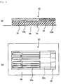
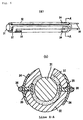
- Figs. 2 through 4 are schematic views showing the flow of production of the ceramic heater 10.
- (a) represents a sectional view and (b) represents a plan view.
- an adhesive layer 22 is first formed on a releasable plastic film 21 and, then, a conductive paste layer 23a forming said resistance heating element 13 and a conductive paste layer 23b forming said terminals 14 are formed.
- the adhesive layer 22 is formed in order that, in assembling the heater, the parts of terminals 14 which are to be exposed through the cutouts 15 may be firmly secured to the core 11. Moreover, the conductive paste layer 23a and conductive paste layer 23b are disposed one adjoining the other so that they may be firmly secured to each other.
- a green sheet layer 24 for said intermediate layer 17 is formed so as to cover most of the conductor paste layer 23a and conductor paste layer 23b.
- a green sheet 25 layer to serve as an insulation sheet 12 is formed on top of the green sheet layer 24 so as to cover the whole assembly.
- the green sheet 24 to serve as said intermediate layer 17 may be disposed in such a manner that it covers only the conductive paste layer 23a or only the part where the temperature reaches 300°C or higher in use of the heater.
- the laminate 20 shown in Fig. 3 is turned back so that the insulation sheet 25 will become the underside and set rigidly on a platform 26 by means of, for instance, air suction. Then, a plastic film 21 is peeled off. Thereafter, although not illustrated in Fig. 4, the core 11 is set in position on the laminate 20 which is then wrapped around said core 11 to construct a green molding for firing. This green molding is sintered at a predetermined temperature to provide the ceramic heater 10.
- the resistance heating element is surrounded by an intermediate layer which is lean in SiO 2 , MgO, etc. and, hence, hardly allows migration of MgO etc. Therefore, the resistance heating element will hardly be oxidized even if a direct current flows through the ceramic heater for many consecutive hours, with the result that the change in resistance of the resistance heating element due to such oxidation and the degradation of the heater by aging can be successfully prevented.
- the ceramic heater 10 shown in Fig. 1 was fabricated.
- the sintering temperature used was 1600 °C.
- the resistance heating element 13 of the ceramic heater 10 thus fabricated was composed of 80 weight % of W, 17 weight % of Re and 3 weight % of Al 2 O 3 ;
- the intermediate layer 17 was comprised of alumina ceramics having a thickness of 15 ⁇ m and containing 0.1 weight % of SiO 2 , 0.05 weight % of MgO and 0.05 weight % of CaO;
- the insulation sheet 12 was composed of 92.5 weight % of Al 2 O 3 supplemented with, as sintering aids, 5.8 weight % of SiO 2 , 0.5 weight % of MgO and 1.2 weight % of CaO and had a thickness of 200 ⁇ m.
- the ceramic heater 10 thus fabricated was connected to a DC source, whereupon the heater temperature rose to 1000°C. The time to a 10% change in resistance was measured. The time was 10000 hours.
- the percent change in resistance can be expressed by the following expression (1).
- Change in resistance (%) [(resistance value after test - resistance value before test) ⁇ 100] / (resistance value before test)
- a ceramic heater was fabricated according to the conventional design illustrated in Fig. 5.
- the sintering temperature was 1600°C.
- the material formulation for the resistance heating element 13 of the ceramic heater 30 was the same as that used in Example 1, and the insulation sheet 12 was composed of 85 weight % of Al 2 O 3 supplemented with, as sintering aids, 12 weight % of SiO 2 , 1.0 weight % of MgO and 2.0 weight % of CaO and had a thickness of 250 ⁇ m. No intermediate layer was provided.
- the ceramic heater 30 thus obtained was connected to a DC source.
- the time to a 10% change in resistance was measured in the same manner as in Example 1. The time was found to be 6000 hours.
- the resistance heating element is not easily oxidized so that the resistance change of the resistance heating element due to such oxidation and heater degradation due to aging can be effectively inhibited.
Landscapes
- Chemical & Material Sciences (AREA)
- Engineering & Computer Science (AREA)
- Ceramic Engineering (AREA)
- Resistance Heating (AREA)
- Compositions Of Oxide Ceramics (AREA)
Abstract

Description
Claims (5)
- A ceramic heater which comprisesan insulation sheet comprising 88 to 95 weight % of Al2O3 supplemented with, as sintering aids, 3 to 10 weight % of SiO2, 0.4 to 1.0 weight % of MgO and 1.0 to 2.5 weight % of CaO,a core covered with said insulation sheet,a resistance heating element of high-melting metal as interposed between said insulation sheet and said core,an intermediate layer of an alumina ceramic body having a thickness of 5 to 50 µm, andsaid alumina ceramic body containing 0.05 to 4 weight % of SiO2, 0.01 to 0.5 weight % of MgO and 0.01 to 1.2 weight % of CaO as interposed between at least a part of said resistance heating element and said core and/or between at least a part of said resistance heating element and said insulation sheet.
- The ceramic heater according to Claim 1
wherein the intermediate layer is interposed between said at least a part of the resistance heating element and the insulation sheet. - The ceramic heater according to Claim 1
wherein the intermediate layer is interposed between said at least a part of the resistance heating element and the core and between said at least a part of the resistance heating element and the insulation sheet. - The ceramic heater according to Claim 1, 2 or 3
wherein the intermediate layer is disposed in a high-temperature part where the operating temperature of the resistance heating element reaches 300°C or higher. - The ceramic heater according to Claim 1, 2, 3 or 4
wherein the intermediate layer has a thickness of 10 to 15 µm.
Applications Claiming Priority (2)
| Application Number | Priority Date | Filing Date | Title |
|---|---|---|---|
| JP11086688A JP2000286045A (en) | 1999-03-29 | 1999-03-29 | Ceramic heater |
| JP8668899 | 1999-03-29 |
Publications (2)
| Publication Number | Publication Date |
|---|---|
| EP1041858A2 true EP1041858A2 (en) | 2000-10-04 |
| EP1041858A3 EP1041858A3 (en) | 2001-05-16 |
Family
ID=13893934
Family Applications (1)
| Application Number | Title | Priority Date | Filing Date |
|---|---|---|---|
| EP00106046A Withdrawn EP1041858A3 (en) | 1999-03-29 | 2000-03-29 | Ceramic heater |
Country Status (3)
| Country | Link |
|---|---|
| US (1) | US6218648B1 (en) |
| EP (1) | EP1041858A3 (en) |
| JP (1) | JP2000286045A (en) |
Cited By (1)
| Publication number | Priority date | Publication date | Assignee | Title |
|---|---|---|---|---|
| EP4351272A4 (en) * | 2021-05-27 | 2025-07-16 | Kyocera Corp | RADIATOR |
Families Citing this family (3)
| Publication number | Priority date | Publication date | Assignee | Title |
|---|---|---|---|---|
| KR20080108372A (en) * | 2003-12-24 | 2008-12-12 | 쿄세라 코포레이션 | Ceramic heater and its manufacturing method |
| US11457513B2 (en) | 2017-04-13 | 2022-09-27 | Bradford White Corporation | Ceramic heating element |
| JP6792539B2 (en) * | 2017-10-31 | 2020-11-25 | 日本特殊陶業株式会社 | Ceramic heater for fluid heating |
Family Cites Families (4)
| Publication number | Priority date | Publication date | Assignee | Title |
|---|---|---|---|---|
| JP2804393B2 (en) * | 1991-07-31 | 1998-09-24 | 京セラ株式会社 | Ceramic heater |
| JP3401648B2 (en) * | 1993-07-23 | 2003-04-28 | 日本特殊陶業株式会社 | Bar-shaped ceramic heater for oxygen sensor and method of manufacturing the same |
| KR100361113B1 (en) * | 1994-08-18 | 2003-02-05 | 닛뽕도구슈우도오교오가부시끼가이샤 | Alumina-based sintered material for ceramic heater |
| JP3691649B2 (en) * | 1997-10-28 | 2005-09-07 | 日本特殊陶業株式会社 | Ceramic heater |
-
1999
- 1999-03-29 JP JP11086688A patent/JP2000286045A/en active Pending
-
2000
- 2000-03-29 US US09/537,184 patent/US6218648B1/en not_active Expired - Lifetime
- 2000-03-29 EP EP00106046A patent/EP1041858A3/en not_active Withdrawn
Cited By (1)
| Publication number | Priority date | Publication date | Assignee | Title |
|---|---|---|---|---|
| EP4351272A4 (en) * | 2021-05-27 | 2025-07-16 | Kyocera Corp | RADIATOR |
Also Published As
| Publication number | Publication date |
|---|---|
| EP1041858A3 (en) | 2001-05-16 |
| US6218648B1 (en) | 2001-04-17 |
| JP2000286045A (en) | 2000-10-13 |
Similar Documents
| Publication | Publication Date | Title |
|---|---|---|
| CA2004241C (en) | Ceramic case capacitor | |
| TWI500063B (en) | Circuit protection device including resistor and fuse element | |
| EP1041859A3 (en) | Heater with PTC element | |
| US5474834A (en) | Superconducting circuit sub-assembly having an oxygen shielding barrier layer | |
| US5488348A (en) | PTC thermistor | |
| US6236027B1 (en) | Ceramic heater | |
| US4598676A (en) | Glow plug for an internal combustion engine | |
| US6218648B1 (en) | Ceramic heater | |
| US6265700B1 (en) | Ceramic heater | |
| US11791070B2 (en) | NTC thermistor element | |
| US11967445B2 (en) | NTC thermistor element | |
| JPH08138906A (en) | Manufacture of positive temperature coefficient(ptc) thermistor device and heat detecting device | |
| JP3452282B2 (en) | Composite thermistor temperature sensor | |
| WO1996020577A1 (en) | Rapid heating element and its manufacturing method | |
| JP3286855B2 (en) | Manufacturing method of chip type PTC thermistor | |
| JP3667099B2 (en) | High temperature thermistor element, manufacturing method thereof, and temperature sensor for high temperature using the same | |
| US5186809A (en) | Structure for joining a wire to a solid electrolytic element | |
| JP2000286046A (en) | Ceramic heater | |
| US20260081078A1 (en) | Electronic component | |
| JP2001102156A (en) | Method for fabricating a ceramic heater | |
| JP2001102161A (en) | Ceramic heater | |
| JPH0648219B2 (en) | Temperature sensor | |
| JPH1012404A (en) | Laminated PTC thermistor and method of manufacturing the same | |
| JP3826465B2 (en) | Manufacturing method of polymer PTC thermistor | |
| JP2001102154A (en) | Ceramic heater |
Legal Events
| Date | Code | Title | Description |
|---|---|---|---|
| PUAI | Public reference made under article 153(3) epc to a published international application that has entered the european phase |
Free format text: ORIGINAL CODE: 0009012 |
|
| AK | Designated contracting states |
Kind code of ref document: A2 Designated state(s): DE FR GB IT SE |
|
| AX | Request for extension of the european patent |
Free format text: AL;LT;LV;MK;RO;SI |
|
| PUAL | Search report despatched |
Free format text: ORIGINAL CODE: 0009013 |
|
| AK | Designated contracting states |
Kind code of ref document: A3 Designated state(s): AT BE CH CY DE DK ES FI FR GB GR IE IT LI LU MC NL PT SE |
|
| AX | Request for extension of the european patent |
Free format text: AL;LT;LV;MK;RO;SI |
|
| AKX | Designation fees paid |
Free format text: DE FR GB IT SE |
|
| STAA | Information on the status of an ep patent application or granted ep patent |
Free format text: STATUS: THE APPLICATION IS DEEMED TO BE WITHDRAWN |
|
| 18D | Application deemed to be withdrawn |
Effective date: 20011119 |