EP1041770A2 - Radio communication system and terminal using faster and slower networks - Google Patents
Radio communication system and terminal using faster and slower networks Download PDFInfo
- Publication number
- EP1041770A2 EP1041770A2 EP00302771A EP00302771A EP1041770A2 EP 1041770 A2 EP1041770 A2 EP 1041770A2 EP 00302771 A EP00302771 A EP 00302771A EP 00302771 A EP00302771 A EP 00302771A EP 1041770 A2 EP1041770 A2 EP 1041770A2
- Authority
- EP
- European Patent Office
- Prior art keywords
- network
- terminal
- terminal device
- respect
- interface
- Prior art date
- Legal status (The legal status is an assumption and is not a legal conclusion. Google has not performed a legal analysis and makes no representation as to the accuracy of the status listed.)
- Granted
Links
Images







Classifications
-
- H—ELECTRICITY
- H04—ELECTRIC COMMUNICATION TECHNIQUE
- H04W—WIRELESS COMMUNICATION NETWORKS
- H04W28/00—Network traffic management; Network resource management
- H04W28/16—Central resource management; Negotiation of resources or communication parameters, e.g. negotiating bandwidth or QoS [Quality of Service]
- H04W28/18—Negotiating wireless communication parameters
- H04W28/22—Negotiating communication rate
-
- H—ELECTRICITY
- H04—ELECTRIC COMMUNICATION TECHNIQUE
- H04L—TRANSMISSION OF DIGITAL INFORMATION, e.g. TELEGRAPHIC COMMUNICATION
- H04L12/00—Data switching networks
- H04L12/54—Store-and-forward switching systems
- H04L12/56—Packet switching systems
- H04L12/5691—Access to open networks; Ingress point selection, e.g. ISP selection
- H04L12/5692—Selection among different networks
-
- H—ELECTRICITY
- H04—ELECTRIC COMMUNICATION TECHNIQUE
- H04W—WIRELESS COMMUNICATION NETWORKS
- H04W12/00—Security arrangements; Authentication; Protecting privacy or anonymity
- H04W12/06—Authentication
-
- H—ELECTRICITY
- H04—ELECTRIC COMMUNICATION TECHNIQUE
- H04W—WIRELESS COMMUNICATION NETWORKS
- H04W84/00—Network topologies
- H04W84/02—Hierarchically pre-organised networks, e.g. paging networks, cellular networks, WLAN [Wireless Local Area Network] or WLL [Wireless Local Loop]
- H04W84/10—Small scale networks; Flat hierarchical networks
- H04W84/12—WLAN [Wireless Local Area Networks]
-
- H—ELECTRICITY
- H04—ELECTRIC COMMUNICATION TECHNIQUE
- H04W—WIRELESS COMMUNICATION NETWORKS
- H04W88/00—Devices specially adapted for wireless communication networks, e.g. terminals, base stations or access point devices
- H04W88/02—Terminal devices
-
- H—ELECTRICITY
- H04—ELECTRIC COMMUNICATION TECHNIQUE
- H04W—WIRELESS COMMUNICATION NETWORKS
- H04W88/00—Devices specially adapted for wireless communication networks, e.g. terminals, base stations or access point devices
- H04W88/02—Terminal devices
- H04W88/04—Terminal devices adapted for relaying to or from another terminal or user
-
- H—ELECTRICITY
- H04—ELECTRIC COMMUNICATION TECHNIQUE
- H04W—WIRELESS COMMUNICATION NETWORKS
- H04W88/00—Devices specially adapted for wireless communication networks, e.g. terminals, base stations or access point devices
- H04W88/02—Terminal devices
- H04W88/06—Terminal devices adapted for operation in multiple networks or having at least two operational modes, e.g. multi-mode terminals
-
- H—ELECTRICITY
- H04—ELECTRIC COMMUNICATION TECHNIQUE
- H04W—WIRELESS COMMUNICATION NETWORKS
- H04W92/00—Interfaces specially adapted for wireless communication networks
- H04W92/02—Inter-networking arrangements
Definitions
- the present invention relates to a radio terminal device (which is also referred to as a wireless terminal device) having a plurality of communication interfaces and a radio communication system (which is also referred to as a wireless communication system) including such radio terminal devices.
- a radio terminal device which is also referred to as a wireless terminal device
- a radio communication system which is also referred to as a wireless communication system
- the IEEE 1394 bus is capable of connecting a plurality of terminals in daisy chain or star connection and transferring a wideband data in excess of 100 Mbps. Also, it has a major feature that it is possible to transmit both asynchronous data and isochronous data on the same cable. For this reason, even though the IEEE 1394 bus was originally developed as a next generation version of SCSI, there are increasing trends to use the IEEE 1394 bus as a cable for connecting AV devices.
- a radio system using 5 GHz band is currently proposed. This proposition is aimed at the realization of a radio system capable of realizing the transmission rate of about 20 to 30 Mbps, by which several channels of MPEG2 video data can be transferred. Also, the 5 GHz band radio frequencies are said to be the last frequencies that can penetrate through many walls present in the home environment, so that this is the most promising candidate for the wideband radio system for home use.
- the 5 GHz band radio system also has its own problems. Namely, it is currently impossible to realize LSI of the RF function using CMOS. This is a severe drawback in view of a low cost realization of the 5 GHz radio system, and its resolution is imperative since it is expected that wider spread of radio systems in the home environment critically depends on how cheaply this 5 GHz band radio system can be offered to the general users.
- a radio device for transferring wideband data such as 5 GHz band radio system is expected to be rather expensive, and for this reason it is expected that a cost of the radio terminal itself will be very high in realizing the video data delivery in the home environment. This is a very serious problem for very cost sensitive products such as home electronic devices.
- a communication system comprising: a first terminal device connected to first and second networks, having only a reception function with respect to the first network and transmission and reception functions with respect to the second network, the first network being a radio network according to IEEE 802.11 and the second network being a radio network slower than the first network; and a second terminal device connected to the first and second networks, having at least a transmission function with respect to the first network and transmission and reception functions with respect to the second network; wherein the first terminal device carries out a prescribed procedure required in using the first terminal as a receiving side in the first network, by carrying out communications with the second terminal device through the second network; the second terminal device transmits a prescribed information to the first network on behalf of the first terminal device, the prescribed information being an information required to be transmitted to the first network in order for the first terminal device to receive packets through the first network; and the first terminal device receives the packets through the first network.
- a terminal device comprising: a first interface configured to carry out at least a packet transmission with respect to a first network which is a radio network according to IEEE 802.11; a second interface configured to carry out packet transmission and reception with respect to a second network which is a radio network slower than the first network; and a control unit configured to carry out communications with another terminal through the second interface so as to carry out a prescribed procedure required in using the another terminal as a receiving side in the first network, and transmit a prescribed information to the first network on behalf of the another terminal, the prescribed information being an information required to be transmitted to the first network in order for the another terminal to receive packets through the first network, such that the another terminal can receive the packets through the first network.
- a terminal device comprising: a first interface configured to carry out at least a packet reception with respect to a first network which is a radio network according to IEEE 802.11; a second interface configured to carry out packet transmission and reception with respect to a second network which is a radio network slower than the first network; and a control unit configured to carry out communications with another terminal through the second interface so as to carry out a prescribed procedure required in using own terminal as a receiving side in the first network, such that the another terminal transmits a prescribed information to the first network on behalf of the own terminal, the prescribed information being an information required to be transmitted to the first network in order for the own terminal to receive packets through the first network, and receive the packets through the first network.
- a communication system comprising: a first terminal device connected to first and second networks, having only a reception function with respect to the first network and transmission and reception functions with respect to the second network, the first network being a radio network according to IEEE 802.11 and the second network being a radio network slower than the first network; a second terminal device connected to the first network and a third network different from the first and second networks, having at least a transmission function with respect to the first network and transmission and reception functions with respect to the third network; a third terminal device connected to the second and third networks, having transmission and reception functions with respect to the second and third networks; and a fourth device provided on the third network, having transmission and reception functions with respect to the third networks; wherein the first terminal device carries out a prescribed procedure required in using the first terminal as a receiving side in the first network, by carrying out communications with the third terminal device through the second network; the third terminal device carries out the prescribed procedure by carrying out communications with the second terminal device through the third network; the third terminal device carries
- a terminal device for carrying out a data transfer with respect to a first terminal through a first network, under a control of a second terminal, the first terminal having only a reception function with respect to the first network and transmission and reception functions with respect to a second network, the first network being a radio network according to IEEE 802.11 and the second network being a radio network slower than the first network, the second terminal being connected to the second network and a third network different from the first and second networks and having transmission and reception functions with respect to the second and third networks, the terminal device comprising: a first interface configured to carry out at least a packet transmission with respect to the first network; a second interface configured to carry out packet transmission and reception with respect to the third network; and a control unit configured to receive a control information transferred from the second terminal through the third network, and transfer packets received from a third device provided on the third network, to the first terminal through the first network according to the control information.
- a terminal device for controlling a data transfer with respect to a first terminal through a first network from a second terminal, the first terminal having only a reception function with respect to the first network and transmission and reception functions with respect to a second network, the first network being a radio network according to IEEE 802.11 and the second network being a radio network slower than the first network, the second terminal being connected to the first network and a third network different from the first and second networks and having at least a transmission function with respect to the first network and transmission and reception functions with respect to the third network, the terminal device comprising: a first interface configured to carry out packet transmission and reception with respect to the second network; a second interface configured to carry out packet transmission and reception with respect to the third network; and a control unit configured to carry out communications with the first terminal through the first interface and communications with the second terminal through the second interface, so as to carry out a prescribed procedure required in using the first terminal as a receiving side in the first network, carry out another prescribed procedure required in relaying packets transferred from
- a terminal device for receiving a data transfer through a first network from a first terminal by utilizing a second terminal through a second network, the first network being a radio network according to IEEE 802.11 and the second network being a radio network slower than the first network, the first terminal being connected to the first network and a third network different from the first and second networks and having at least a transmission function with respect to the first network and transmission and reception functions with respect to the third network, and the second terminal being connected to the second network and the third network and having transmission and reception functions with respect to the second and third networks, the terminal device comprising: a first interface configured to carry out at least a packet reception with respect to a first network which is a radio network according to IEEE 802.11; a second interface configured to carry out packet transmission and reception with respect to a second network which is a radio network slower than the first network; and a control unit configured to carry out communications with the second terminal through the second interface so as to carry out a prescribed procedure required in using own terminal as a
- a method of packet transfer in a communication system including a first terminal device connected to first and second networks, having only a reception function with respect to the first network and transmission and reception functions with respect to the second network, the first network being a radio network according to IEEE 802.11 and the second network being a radio network slower than the first network, and a second terminal device connected to the first and second networks, having at least a transmission function with respect to the first network and transmission and reception functions with respect to the second network, the method comprising the steps of: carrying out a prescribed procedure required in using the first terminal as a receiving side in the first network, by carrying out communications between the first terminal device and the second terminal device through the second network; transmitting a prescribed information from the second terminal device to the first network on behalf of the first terminal device, the prescribed information being an information required to be transmitted to the first network in order for the first terminal device to receive packets through the first network; and receiving the packets at the first terminal device through the first network.
- a method of packet transfer in a communication system including a first terminal device connected to first and second networks, having only a reception function with respect to the first network and transmission and reception functions with respect to the second network, the first network being a radio network according to IEEE 802.11 and the second network being a radio network slower than the first network, a second terminal device connected to the first network and a third network different from the first and second networks, having at least a transmission function with respect to the first network and transmission and reception functions with respect to the third network, a third terminal device connected to the second and third networks, having transmission and reception functions with respect to the second and third networks, and a fourth device provided on the third network, having transmission and reception functions with respect to the third networks, the method comprising the steps of: carrying out a prescribed procedure required in using the first terminal as a receiving side in the first network, by carrying out communications between the first terminal device and the third terminal device through the second network; carrying out the prescribed procedure by carrying out communications between the third terminal device and the second terminal device through
- Fig. 1 is a schematic diagram showing a configuration of a network system according to the first embodiment of the present invention.
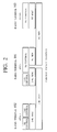
- Fig. 2 is a diagram showing a protocol stack for a control packet transfer protocol used in the network system of Fig. 1.
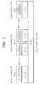
- Fig. 3 is a diagram showing a protocol stack for a data packet transfer protocol used in the network system of Fig. 1.
- Fig. 4 is a block diagram for explaining one exemplary processing for packet transfer among radio terminals in the network system of Fig. 1.
- Fig. 5 is a block diagram for explaining another exemplary processing for packet transfer among radio terminals in the network system of Fig. 1.
- Fig. 6 is a diagram showing a processing sequence for communications among radio terminals in the network system of Fig. 1.
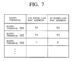
- Fig. 7 is a diagram showing a MAC address correspondence table that can be used in the network system of Fig. 1.
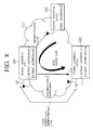
- Fig. 8 is a schematic diagram showing a configuration of a network system according to the second embodiment of the present invention.
- Fig. 9 is a diagram showing a processing sequence for communications among radio terminals in the network system of Fig. 8, in the case of direct packet transfer.
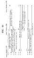
- Fig. 10 is a diagram showing a processing sequence for communications among radio terminals in the network system of Fig. 8, in the case of packet transfer relaying.
- Fig. 11 is a schematic diagram showing a configuration of a network system according to the third embodiment of the present invention.
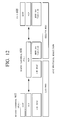
- Fig. 12 is a diagram showing a protocol stack for a AV/C protocol execution used in the network system of Fig. 11.
- Fig. 13 is a diagram showing a protocol stack for a MPEG2 data transfer protocol used in the network system of Fig. 11.
- Fig. 14 is a diagram showing a network configuration as recognized by a radio terminal and a node on IEEE 1394 bus, and exemplary communication resources reserved in the network system of Fig. 11.
- Fig. 15 is a diagram showing a processing sequence for communications among radio terminals in the network system of Fig. 11.
- Fig. 16 is a schematic diagram showing a configuration of a network system according to the fourth embodiment of the present invention.
- Fig. 17 is a diagram showing a first half of a processing sequence for communications among radio terminals in the network system of Fig. 16.
- Fig. 18 is a diagram showing a second half of a processing sequence for communications among radio terminals in the network system of Fig. 16.
- Fig. 1 to Fig. 7 the first embodiment of a radio communication system and a radio terminal device according to the present invention will be described in detail.
- This first embodiment is directed to a scheme by which a radio terminal having only a reception function with respect to the 5 GHz band radio LAN (or capable of utilizing only a reception function with respect to the 5 GHz band radio LAN) carries out a processing (such as authentication/admission processing, for example) with respect to the 5 GHz band radio LAN, via the 2.4 GHz band radio LAN.
- a processing such as authentication/admission processing, for example
- Fig. 1 shows an exemplary configuration of a network system in which the 5 GHz band radio LAN and the 2.4 GHz band radio LAN are used cooperatively. These radio LANs are both operated according to the IEEE 802.11 protocol, but uses different radio frequencies so that there is no interference between them.
- the network system of Fig. 1 includes a radio terminal 101 which provides a P.C. (Point Coordinator) function in the 5 GHz band radio LAN 121, a radio terminal 103 which has transmission and reception functions with respect to the 5 GHz band radio LAN, and a radio terminal 102 which has only a reception function with respect to the 5 GHz band radio LAN.
- the radio terminal 101 and the radio terminal 102 have transmission and reception functions with respect to the 2.4 GHz band radio LAN by which they can communicate with each other.
- each of the radio terminal 101 and the radio terminal 102 has a MAC address on the 2.4 GHz band radio LAN and a MAC address on the 5 GHz band radio LAN separately, but it is also possible to use the same MAC address for the MAC address on the 2.4 GHz band radio LAN and the MAC address on the 5 GHz band radio LAN.
- the radio terminal 101 has an address "X1" on the 2.4 GHz band radio LAN and an address "X2" on the 5 GHz band radio LAN
- the radio terminal 102 has an address "Y1” on the 2.4 GHz band radio LAN and an address "Y2” on the 5 GHz band radio LAN
- the radio terminal 103 has an address "Z" on the 5 GHz band radio LAN.
- a radio terminal authentication processing should be carried out between these radio terminal prior to the communication.
- a radio terminal admission processing should be carried out between the radio terminal and the P.C. (the radio terminal 101 in the case of Fig. 1) as a processing for making the connection.
- the radio terminal 102 has only a reception function with respect to the 5 GHz band radio LAN, so that this radio terminal 102 cannot directly carry out the authentication/admission processing using the 5 GHz band radio frequencies at a time of carrying out a communication with another radio terminal (the radio terminal 101 or the radio terminal 103, for example).
- the radio terminal 102 having only a reception function with respect to the 5 GHz band radio LAN carries out the authentication/admission processing with respect to the 5 GHz band radio LAN, via the 2.4 GHz band radio LAN.
- the radio terminal 102 In order to carry out the authentication processing according to the IEEE 802.11, it is necessary for both terminals to notify each other an authentication algorithm that is executable on the own terminal as well as the MAC address of the own terminal. For this reason, in order for the radio terminal 102 that has only a reception function with respect to the 5 GHz band radio LAN to carry out the authentication processing with another radio terminal in the 5 GHz band radio LAN, there is a need to notify the information necessary for the authentication processing (the executable authentication algorithm and the MAC address) using a different route. In Fig. 1, the 2.4 GHz band radio LAN is utilized for this purpose. Similarly, in the case where the radio terminal 102 makes a connection to the radio terminal 101 which is the P.C. of the 5 GHz band radio LAN, there is a need for the radio terminal 102 to notify the MAC address of the own terminal to the radio terminal 101, and in Fig. 1, the 2.4 GHz band radio LAN is also utilized for this purpose.
- Fig. 2 shows a protocol stack indicating how the authentication/admission processing is carried out between the radio terminal 101 and the radio terminal 103 in this case.
- the authentication/admission processing with respect to the 5 GHz band radio LAN is abbreviated as "5G control”
- the authentication/admission processing with respect to the 2.4 GHz band radio LAN is abbreviated as "2.4G control”.
- the authentication/admission processing of the radio terminal 102 with respect to the 5 GHz band radio LAN is carried out at the radio terminal 101 which is the P.C. of the 5 GHz band radio LAN, via the 2.4 GHz band radio LAN.
- the authentication/admission processing with respect to the 5 GHz band radio LAN is carried out via the 5 GHz band radio LAN.
- Fig. 3 shows a protocol stack indicating how the actual data transfer is carried out between the radio terminal 101 and the radio terminal 102, as well as between the radio terminal 101 and the radio terminal 103.
- the actual data are transferred via the 5 GHz band radio LAN, but only data transmitted from the radio terminal 101 towards the radio terminal 102 will be transferred to the radio terminal 102.
- a packet identification method on the 2.4 GHz band radio LAN must be devised. Namely, it is necessary to specify which layer should be used by the radio terminal 101 in order to identify a packet on which the control information for the 5 GHz band radio LAN is loaded among the packets received at an interface with respect to the 2.4 GHz band radio LAN.
- Fig. 4 and Fig. 5 show various drivers operating on each MAC layer, in addition to the physical and MAC layers of the 2.4 GHz band radio LAN and the 5 GHz band radio LAN (denoted in the figures as 2.4G-PHY, 2.4G-MAC, 5G-PHY, and 5G-MAC respectively).
- control drivers for handling the authentication/admission, the data transfer request, etc., and data drivers for handling the actual data transfer are distinguished.
- Fig. 4 and Fig. 5 also show various applications to be executed using these drivers, including an ordinary application to be executed on the 2.4 GHz band radio LAN (abbreviated as 2.4G application in the figures), an ordinary application to be executed on the 5 GHz band radio LAN (abbreviated as 5G application in the figures), and an AWL (Asymmetric Wireless Link) application in which the control information is exchanged via the 2.4 GHz band radio LAN and the actual data are transferred on the 5 GHz band radio LAN.
- 2.4G application an ordinary application to be executed on the 5 GHz band radio LAN
- 5G application abbreviated as 5G application in the figures
- AWL Asymmetric Wireless Link
- a dotted line indicates a packet transfer route in the case of executing the ordinary application on the 2.4 GHz band radio LAN
- a dashed line indicates a packet transfer route in the case of executing the ordinary application on the 5 GHz band radio LAN
- a solid line indicates a packet transfer route in the case of executing the AWL application.
- the radio terminal 103 is an ordinary terminal on the 5 GHz band radio LAN so that the processing according to the ordinary (IEEE 802.11) protocol of the 5 GHz band radio LAN is carried out between the radio terminal 101 and the radio terminal 103.
- the radio terminal 101 After receiving a packet at a physical layer processing unit (2.4G-PHY in Fig. 4) for the 2.4 GHz band radio LAN, the radio terminal 101 carries out the "packet distributing" processing for identifying whether the received packet is a packet corresponding to the application on the 2.4 GHz band radio LAN or a packet corresponding to the AWL application at a MAC layer processing unit (2.4G-MAC in Fig. 4) which is an upper layer processing unit of the physical layer processing unit.
- a "packet distributing" processing unit is provided in the MAC layer processing unit for this purpose.
- data to be transmitted from the AWL application on the radio terminal 101 towards the radio terminal 102 are transferred to the "packet distributing" processing unit within the MAC layer processing unit (5G-MAC in Fig. 4) for the 5 GHz band radio LAN via its data driver.
- the fact that this data packet is transmitted from the AWL application is indicated by a flag on the MPDU, and then the packet transmission processing is carried out according to a packet transmission algorithm using a unidirectional downlink from the radio terminal 101 to the radio terminal 102.
- the "packet distributing" processing unit within the MAC layer processing unit for the 5 GHz band radio LAN will be unnecessary.
- the radio terminal 102 executes the AWL application on the own terminal, the control processing necessary for it is carried out on the 2.4 GHz band radio LAN. For this reason, a packet carrying the control information that is transmitted from the AWL application is transferred to the "packet distributing" processing unit within the MAC layer processing unit (2.4G-MAC in Fig. 4) for the 2.4 GHz band radio LAN via the control driver of the AWL application.
- the fact that this packet is a control packet for executing the AWL application is indicated by a flag on the MPDU, and then this packet is transferred to the radio terminal 101 via the MAC/physical layer processing units for the 2.4 GHz band radio LAN.
- the radio terminal 102 has only a reception function (5G-PHY(R), 5G-MAC(R) in Fig. 4) with respect to the 5 GHz band radio LAN, and is capable of executing only the AWL application using this function.
- the radio terminal 102 receives only data packets of the AWL application from the 5 GHz band radio LAN.
- packets received at an interface with respect to the 5 GHz band radio LAN of the radio terminal 102 are all to be transferred to the AWL application, so that all the packets from the MAC layer processing unit for the 5 GHz band radio LAN will be transferred to the data driver of the AWL application, and the "packet distributing" processing as used in the radio terminal 101 is unnecessary in the radio terminal 102.
- the radio terminal 102 executes only the packet reception processing with respect to the 5 GHz band radio LAN so that the execution of the AWL application between the radio terminal 101 and the radio terminal 102 is possible even when the same MAC address is used as the MAC address on the 2.4 GHz band radio LAN and the MAC address on the 5 GHz band radio LAN of the radio terminal 102.
- the "packet distributing" processing unit of the radio terminal 101 it is necessary for the "packet distributing" processing unit of the radio terminal 101 to recognize in advance that the MAC address on the 2.4 GHz band radio LAN and the MAC address on the 5 GHz band radio LAN of the radio terminal 102 are the same.
- Fig. 5 unlike Fig. 4, no new function is added to the MAC layer processing for each radio LAN in the radio terminal 101 and the radio terminal 102, and whether the received packet is a packet for the application on the 2.4 GHz band or 5 GHz band radio LAN or a packet for the AWL application is identified at an upper level driver of the MAC layer.
- the radio terminal 101 transfers a packet received by the physical layer processing unit (2.4G-PHY in Fig. 5) and the MAC layer processing unit (2.4G-MAC in Fig. 5) for the 2.4 GHz band radio LAN, to the corresponding control driver. Then, the MPDU header is removed from the packet received from the MAC layer processing unit, and the information on internal data is checked.
- a field for identifying that the information corresponding to the AWL application is loaded on this packet is defined as one of the information on internal data, and whether the received packet is a packet corresponding to the AWL application or not is judged according to this field.
- This packet identification processing is carried out by the AWL driver defined as an upper level driver of the control and data drivers in Fig. 5.
- data transmitted from the AWL application on the radio terminal 101 towards the radio terminal 102 are transferred as follows. Namely, a packet on which this data is loaded is transferred to the AWL driver at which the information indicating that this is a packet corresponding to the AWL application is attached to this packet, and this packet is transferred to the lower level data driver. Then, this packet with the above information attached is transferred to the radio terminal 102 via the MAC/physical layer processing units for the 5 GHz band radio LAN through the unidirectional downlink.
- the unidirectional packet transfer processing from the radio terminal 101 to the radio terminal 102 can be executed without modifying the ordinary MAC algorithm on the 5 GHz band radio LAN, but if some processing for the purpose of carrying out the unidirectional packet transfer processing is required, a function for executing that processing will be provided in the MAC layer processing unit for the 5 GHz band radio LAN.
- the radio terminal 102 executes the control processing necessary for that purpose on the 2.4 GHz band radio LAN. For this reason, the control packet transmitted from the AWL application is attached with an indication that this packet is a packet corresponding to the AWL application at the AWL driver, and then transferred to the radio terminal 101 via its control driver and the MAC/physical layer processing units for the 2.4 GHz band radio LAN.
- the radio terminal 102 has only a reception function (5G-PHY(R), 5G-MAC(R) in Fig. 5) with respect to the 5 GHz band radio LAN, and is capable of executing only the AWL application using this function.
- the radio terminal 102 receives only data packets of the AWL application from the 5 GHz band radio LAN.
- packets received at an interface with respect to the 5 GHz band radio LAN of the radio terminal 102 are all to be transferred to the AWL application, so that all the packets from the MAC layer processing unit for the 5 GHz band radio LAN will be transferred to the data driver of the AWL application.
- the execution of the AWL application between the radio terminal 101 and the radio terminal 102 can be realized using this scheme.
- Fig. 6 shows an exemplary processing sequence at a time of actually transferring data from the radio terminal 101 to the radio terminal 102 in the radio network operated in this scheme.
- the data transfer processing is carried out by the Contention Mode of the IEEE 802.11 as the transfer protocol on the radio LANs, and the carrier sense processing is carried out prior to a series of data transfer processing from each radio terminal.
- This processing sequence proceeds as follows.
- Fig. 8 to Fig. 10 the second embodiment of a radio communication system and a radio terminal device according to the present invention will be described in detail.
- the data transfer from the radio terminal 101 which is the P.C. to the radio terminal 102 has been described.
- the data transfer from the radio terminal 103 to the radio terminal 102 (in a configuration basically similar to that of the first embodiment) will be described.
- the case of the data transfer from the radio terminal 103 to the radio terminal 102 using the ordinary MAC processing (by the radio terminal 103) and the case of the data transfer from the radio terminal 103 to the radio terminal 102 relayed by the radio terminal 101 which is the P.C. will be described.
- Fig. 8 shows a configuration similar to that of the first embodiment, in which the data transfer from the radio terminal 103 to the radio terminal 102 is realized.
- the radio terminal 102 can ascertain the MAC address of a terminal existing on the 5 GHz band radio LAN from the framework of the IEEE 802.11, and requests a packet transfer from the radio terminal 103 by ascertaining its MAC address accordingly.
- the radio terminal is operated according to the IEEE 802.11 protocol used in the 5 GHz band radio LAN, but the radio terminal 102 is a terminal in which only a reception function with respect to the 5 GHz band radio LAN is provided. Consequently, in this embodiment, there are two cases including the case where the data transfer from the radio terminal 103 to the radio terminal 102 can be realized directly through the 5 GHz band radio LAN and the case where data are transferred from the radio terminal 103 via the radio terminal 101 which has a function for transferring data to the radio terminal 102.
- a processing for ignoring presence/absence of the Ack packet reception at a terminal that transmitted a packet depending on the destination of the packet or a processing to transmit the Ack packet from a terminal other than the destination terminal of the packet (a source terminal, for example) on behalf of the destination terminal.
- a terminal that transmits a packet is a terminal in accordance with the IEEE 802.11 such as the radio terminal 103, so that the former method to ignore the Ack packet cannot be adopted.
- this example is directed to the case of realizing a direct packet transfer from the radio terminal 103 to the radio terminal 102 in which the Ack packet corresponding to a packet transmission from the radio terminal 103 to the radio terminal 102 is transmitted from the radio terminal 101 on behalf of the radio terminal 102.
- Fig. 9 shows an exemplary processing sequence in the case of realizing the direct packet transfer from the radio terminal 103 to the radio terminal 102 using this scheme for transmitting the Ack packet from the radio terminal 101.
- the data transfer processing is carried out by the Contention Mode of the IEEE 802.11 as the transfer protocol on the 5 GHz band radio LAN.
- the radio terminal 102 makes a connection to the 5 GHz band radio LAN using a procedure as described in the first embodiment.
- This processing sequence proceeds as follows.
- a packet transmission interval in the series of packet transmissions from (5) to (8) is the SIFS interval which is the minimum packet transmission interval specified in the IEEE 802.11.
- the radio terminal 103 is capable of communicating only with the radio terminal 101, and the radio terminal 102 is capable of receiving packets only from the radio terminal 101. Therefore, in the case of transferring a packet from the radio terminal 103 to the radio terminal 102, it is necessary to relay the packet at the radio terminal 101.
- This example is directed to the case where the radio terminal 101 that received "a request for packet transfer from the radio terminal 103 to the radio terminal 102" from the radio terminal 102 via the 2.4 GHz band radio LAN will activate two packet transfers including a packet transfer from the radio terminal 103 to the own terminal (radio terminal 101) and a packet transfer from the own terminal (radio terminal 101) to the radio terminal 102.
- Fig. 10 shows an exemplary processing sequence in the case of realizing the packet transfer from the radio terminal 103 to the radio terminal 102 using this scheme.
- the data transfer processing is carried out by the Contention Mode of the IEEE 802.11 as the transfer protocol on the 5 GHz band radio LAN.
- the radio terminal 102 makes a connection to the 5 GHz band radio LAN using a procedure as described in the first embodiment. This processing sequence proceeds as follows.
- Fig. 11 to Fig. 15 the third embodiment of a radio communication system and a radio terminal device according to the present invention will be described in detail.
- This third embodiment is directed to the case of operating the radio network (using the 2.4 GHz band radio LAN and the 5 GHz band radio LAN) together with the IEEE 1394 bus.
- a radio terminal having a P.C. function which is capable of carrying out communications by both the 2.4 GHz band radio LAN and the 5 GHz band radio LAN is provided on the IEEE 1394 bus, and this radio terminal relays the data transfer to the radio terminal which has (or which is capable of utilizing) only a reception function with respect to the 5 GHz band radio LAN from a device on the IEEE 1394 bus such as a DVD.
- the example described here is directed to the case where the radio terminal on the radio network downloads image information from a DVD existing on the IEEE 1394 bus, and in particular the AV control protocol is executed between this radio terminal and the DVD via the 2.4 GHz band radio LAN, and the actual image data are received via the 5 GHz band radio LAN.
- Fig. 11 shows an exemplary configuration of a network system in this case. It is assumed that the radio LANs are operated according to the IEEE 802.11 protocol similarly as in the first and second embodiments.
- the network system of Fig. 11 includes a radio terminal 601 which provides a P.C. function in the 5 GHz band radio LAN 621, a radio terminal 603 which has transmission and reception functions with respect to the 5 GHz band radio LAN, and a radio terminal 602 which has only a reception function with respect to the 5 GHz band radio LAN.
- the radio terminal 601 and the radio terminal 602 have transmission and reception functions with respect to the 2.4 GHz band radio LAN by which they can communicate with each other.
- the radio terminal 601 has an interface with respect to the IEEE 1394 bus 623, and is connected to a TV 604 and a DVD 605 via the IEEE 1394 bus.
- This embodiment is directed to the case where the AV control protocol (AV/C protocol) to be executed between the radio terminal 602 and the DVD 605 is executed via the 2.4 GHz band radio LAN and the IEEE 1394 bus, and as a result the MPEG2 data transmitted from the DVD 605 are transferred to the radio terminal 602 via the IEEE 1394 bus and the 5 GHz band radio LAN.
- AV/C protocol AV/C protocol
- 1394 nodes having 1394 interfaces are recognized in units called Unit, and constituent elements (such as a cassette table section or a CD section in an audio component system, for example) within the 1394 terminal are recognized in units called SubUnit.
- the AV/C protocol is to be executed between the DVD 605 on the IEEE 1394 bus and the radio terminal 602 by recognizing each other at a level of their constituent elements (SubUnits of the AV/C protocol), rather than directly recognizing each other. More specifically, in the case of Fig.
- the constituent element (SubUnit) in the DVD 605 is recognized from a viewpoint of the radio terminal 602 as if it is existing in the radio terminal 601, while the constituent element (SubUnit) in the radio terminal 602 is recognized from a viewpoint of the DVD 605 on the IEEE 1394 bus as if it is existing in the radio terminal 601.
- Fig. 12 shows a protocol stack indicating how the AV/C protocol is executed in this embodiment
- Fig. 13 shows a protocol stack indicating how the actual MPEG2 data transfer is carried out in this embodiment.
- the radio terminal 601 provides a function for terminating the IEEE 1394 bus protocol and connecting the IEEE 1394 bus with the 2.4 GHz band radio LAN or the 5 GHz band radio LAN at a level of an upper layer protocol (such as FCP layer in the AV/C protocol or CIP layer in the MPEG2 data transfer, for example).
- an upper layer protocol such as FCP layer in the AV/C protocol or CIP layer in the MPEG2 data transfer, for example.
- the processing for actually transferring the MPEG2 data on the DVD 605 to the radio terminal 602 according to a request from the radio terminal 602 is carried out as follows. This example is directed to the case where a VTR SubUnit exists in the DVD 605 on the IEEE 1394 bus, a Display SubUnit exists in the radio terminal 602, and the MPEG2 data transfer is carried out between these SubUnits.
- Fig. 14 shows how the DVD 605 and the radio terminal 602 are recognizing each other and what communication resources are reserved in executing the MPEG2 data transfer.
- the Display SubUnit in the radio terminal 602 appears as if it is existing in the radio terminal 601, and this Display SubUnit and the VTR SubUnit is connected through an internal connection B inside the DVD 605, an isochronous channel X on the IEEE 1394 bus, and an internal connection A inside the radio terminal 601.
- the VTR SubUnit in the DVD 605 appears as if it is existing in the radio terminal 601, and this VTR SubUnit and the Display SubUnit is connected through an internal connection D inside the radio terminal 602, a channel Y on the 5 GHz band radio LAN, and an internal connection C inside the radio terminal 601.
- O_Plug and I_Plug provided in the DVD 605 and the radio terminals 601 and 602 are interfaces for carrying out data transmission and reception with respect to the isochronous channel on the IEEE 1394 bus, which are defined by the ISO-IEC 61883 protocol.
- the internal connections A, B, C and D provided in the DVD 605 and the radio terminals 601 and 602 are connections for connecting between SubUnits or between SubUnit and Plug in the 1394 nodes or the radio terminals, which are set up or released by the AV/C protocol.
- the transfer of the MPEG2 data will be commanded after setting up such a communication route using the ISO-IEC 61883 protocol and the AV/C protocol in the configuration of Fig. 11.
- the transfer command will be executed by the AV/C protocol.
- Fig. 15 shows an exemplary processing sequence for transferring the MPEG2 data from the DVD 605 to the radio terminal 602 after reserving communication resources as shown in Fig. 14.
- the ISO-IEC 61883 protocol is executable even on the 5 GHz band radio LAN, so that the MPEG2 data communication on the 5 GHz band radio LAN is transferred through some communication channel (channel Y in Fig. 14) on the 5 GHz band radio LAN.
- the data transfer processing is carried out by the Contention Mode of the IEEE 802.11 as the transfer protocol on the 2.4 GHz band radio LAN and the 5 GHz band radio LAN.
- the radio terminal 602 makes a connection to the 5 GHz band radio LAN using a procedure as described in the first embodiment. This processing sequence proceeds as follows.
- Fig. 16 to Fig. 18 the fourth embodiment of a radio communication system and a radio terminal device according to the present invention will be described in detail.
- This fourth embodiment is directed to the case of the radio network in which the 2.4 GHz band radio LAN and the 5 GHz band radio LAN are operated independently, where both the radio terminal providing the P.C. function on the 2.4 GHz band radio LAN and the radio terminal providing the P.C. function on the 5 GHz band radio LAN are existing on the same IEEE 1394 bus.
- the example described here is also directed to the case where the radio terminal on the radio network downloads image information from a DVD existing on the IEEE 1394 bus, and in particular the AV control protocol is executed between this radio terminal and the DVD via the 2.4 GHz band radio LAN, and the actual image data are received via the 5 GHz band radio LAN.
- the difference between this fourth embodiment and the third embodiment is that a terminal for carrying out communications on the 2.4 GHz band radio LAN and a terminal for carrying out communications on the 5 GHz band radio LAN are different in this fourth embodiment, and that a protocol for notifying control information on the 5 GHz band radio LAN that is transmitted via the 2.4 GHz band radio LAN is executed between these terminals.
- the processing (4) of Fig. 15 for making a connection to the 5 GHz band radio LAN and the processing (6) of Fig. 15 for reflecting the request for plug control processing on the 5 GHz band radio LAN according to the ISO-IEC 61883 protocol into the 5 GHz band radio LAN side that were carried out by the radio terminal 601 of Fig. 11 via the 2.4 GHz band radio LAN in the third embodiment will be executed as a communication protocol between different radio terminals. It is assumed that the control message transfer protocol for this purpose is defined in advance.
- Fig. 16 shows an exemplary configuration of a network system in this case. It is assumed that the radio LANs are operated according to the IEEE 802.11 protocol similarly as in the third embodiment.
- the network system of Fig. 16 includes a radio terminal 1101 which provides a P.C. function in the 5 GHz band radio LAN 1201, a radio terminal 1103 which has transmission and reception functions with respect to the 5 GHz band radio LAN, and a radio terminal 1102 which has only a reception function with respect to the 5 GHz band radio LAN.
- the radio terminal 1102 has transmission and reception functions with respect to the 2.4 GHz band radio LAN by which it can communicate with a radio terminal 1106.
- the radio terminal 1101 and the radio terminal 1106 have interfaces with respect to the same IEEE 1394 bus 1203, and are connected to a TV 1104 and a DVD 1105 via the IEEE 1394 bus.
- This embodiment is also directed to the case where the AV/C protocol to be executed between the radio terminal and the node on the IEEE 1394 bus is executed via the 2.4 GHz band radio LAN, and the MPEG2 data are actually transferred via the IEEE 1394 bus and the 5 GHz band radio LAN.
- Fig. 17 and Fig. 18 show an exemplary processing sequence for transferring the MPEG2 data from the DVD 1105 to the radio terminal 1102 in this case.
- the ISO-IEC 61883 protocol is executable even on the 5 GHz band radio LAN.
- the radio terminal 1102 makes a connection to the 5 GHz band radio LAN using a procedure as described in the first embodiment. This processing sequence proceeds as follows.
- a terminal device which is capable of packet transmission and reception in the second network but which is capable only of packet reception in the first network can carry out a procedure necessary in receiving data through the first network by utilizing the second network, so that this terminal device can be effectively utilized as a packet receiving node in the first network without transmitting any packet to the first network from this terminal device (that is, without requiring a packet transmission function with respect to the first network in this terminal device).
- the radio terminal has only a reception function with respect to the 5 GHz band radio LAN
- the authentication/admission processing in the 5 GHz band radio LAN or the AV control protocol between the radio terminal and the node on the IEEE 1394 bus can be carried out via the 2.4 GHz band radio LAN
- the actual data transfer can be carried out via the 5 GHz band radio LAN, so that the video data on the IEEE 1394 bus can be received through the 5 GHz band radio interface.
- the present invention it is possible to reduce the cost of the radio terminal using expensive components for the 5 GHz band radio communication, for example.
- expensive components for the 5 GHz band radio communication for example.
- by providing only a reception function among the radio communication function, and utilizing an inexpensive radio system for the bidirectional communications it is possible to reduce the number of expensive radio components that are required in the terminal, and thereby reduce the cost of the terminal.
- the video information utilization in the home is mostly in a form of receiving/displaying video transmitted by a TV or satellite broadcast for the purpose of watching broadcast programs. This implies that the most users are likely to only receive the video information and hardly transmit any video information. In view of this fact, it is effective to provide only a reception function in the terminal in order to realize wider spread of the 5 GHz band radio function to many homes at low cost.
- a reception function as an expensive radio function such as the 5 GHz band radio function while also providing a transmission function using another inexpensive radio function such as the 2.4 GHz band radio function, it is possible to provide radio terminals that can receive wideband image data and that can be easily accepted in the home environment.
- each of the radio terminals of the above described embodiments can be conveniently implemented in a form of a software package.
- Such a software package can be a computer program product which employs a storage medium including stored computer code which is used to program a computer to perform the disclosed function and process of the present invention.
- the storage medium may include, but is not limited to, any type of conventional floppy disks, optical disks, CD-ROMs, magneto-optical disks, ROMs, RAMs, EPROMs, EEPROMs, magnetic or optical cards, or any other suitable media for storing electronic instructions.
Landscapes
- Engineering & Computer Science (AREA)
- Computer Networks & Wireless Communication (AREA)
- Signal Processing (AREA)
- Computer Security & Cryptography (AREA)
- Quality & Reliability (AREA)
- Mobile Radio Communication Systems (AREA)
- Small-Scale Networks (AREA)
- Communication Control (AREA)
Abstract
Description
Claims (36)
- A communication system, comprising:a first terminal device connected to first and second networks, having only a reception function with respect to the first network and transmission and reception functions with respect to the second network, the first network being a radio network according to IEEE 802.11 and the second network being a radio network slower than the first network; anda second terminal device connected to the first and second networks, having at least a transmission function with respect to the first network and transmission and reception functions with respect to the second network;wherein the first terminal device carries out a prescribed procedure required in using the first terminal as a receiving side in the first network, by carrying out communications with the second terminal device through the second network;the second terminal device transmits a prescribed information to the first network on behalf of the first terminal device, the prescribed information being an information required to be transmitted to the first network in order for the first terminal device to receive packets through the first network; andthe first terminal device receives the packets through the first network.
- The system of claim 1, wherein the packets are transmitted from a source terminal to the second terminal device through the first network, and then transmitted from the second terminal device to the first terminal device through the first network using a unidirectional downlink defined between the first terminal device and the second terminal device in the first network.
- The system of claim 1, wherein the packets are directly transmitted from a source terminal to the first terminal device through the first network.
- The system of claim 1, wherein the first terminal device notifies a source terminal having transmission and reception functions with respect to the first network to the second terminal device, and the second terminal device transmits an information necessary for the source terminal to transmit the packets destined to the first terminal device through the first network.
- The system of claim 1, wherein the first terminal device notifies a source terminal on a third network different from the first and second networks to the second terminal device, the second terminal device transmits a request for transmitting the packets to the second terminal device to the source terminal through the third network, the source terminal transmits the packets to the second terminal device through the third network, and the second terminal device transfers the packets received from the source terminal through the third network to the first terminal device through the first network.
- The system of claim 1, wherein the first terminal device carries out the prescribed procedure by transmitting a packet containing a control information for the first network and attached with an indication in a MAC layer indicating that the control information is contained in the packet, to the second terminal device through the second network, and
the second terminal device identifies the packet containing the control information by detecting the indication by a processing in the MAC layer. - The system of claim 1, wherein the first terminal device carries out the prescribed procedure by transmitting a packet containing a control information for the first network and an indication indicating that the control information is contained in the packet, to the second terminal device through the second network, and
the second terminal device identifies the packet containing the control information by detecting the indication by a processing in an upper layer of a MAC layer. - A terminal device, comprising:a first interface configured to carry out at least a packet transmission with respect to a first network which is a radio network according to IEEE 802.11;a second interface configured to carry out packet transmission and reception with respect to a second network which is a radio network slower than the first network; anda control unit configured to carry out communications with another terminal through the second interface so as to carry out a prescribed procedure required in using the another terminal as a receiving side in the first network, and transmit a prescribed information to the first network on behalf of the another terminal, the prescribed information being an information required to be transmitted to the first network in order for the another terminal to receive packets through the first network, such that the another terminal can receive the packets through the first network.
- The terminal device of claim 8, wherein the control unit also receives an interface address of an interface of the another terminal for carrying out a packet reception through the first network, from the another terminal through the second interface, and transmits the packets through the first interface towards the interface address received from the another terminal.
- The terminal device of claim 8, wherein the control unit also receives an authentication/admission request with respect to the first network from the another terminal through the second interface, and carries out an authentication/admission processing with respect to the first network through the first interface on behalf of the another terminal, according to the authentication/admission request received from the another terminal.
- The terminal device of claim 8, wherein the control unit also receives a packet transmission request with respect to the first network from the another terminal through the second interface, and transmits the packets through the first interface according to the packet transmission request received from the another terminal.
- The terminal device of claim 11, wherein the control unit also transmits another packet transmission request requesting packet transmission from a source terminal to own terminal through the first network, when the source terminal indicated in the packet transmission request received from the another terminal is not the own terminal, receives the packets transmitted from the source terminal through the first network according to the another packet transmission request, and transfers the packets to the another terminal through the first interface.
- The terminal device of claim 8, wherein the control unit also receives a resource acquisition request with respect to the first network from the another terminal, and carries out a resource acquisition processing on the first network according to the resource acquisition request received from the another terminal.
- The terminal device of claim 8, wherein the control unit also judges whether a packet received from the another terminal through the second interface contains a control information for the first network or not, and carries out a processing corresponding to the control information with respect to the first network when the packet received from the another terminal contains the control information.
- The terminal device of claim 14, wherein the control unit also stores a correspondence between a first interface address and a second interface address of each terminal existing on the first network, the first interface address being an address of an interface of each terminal for carrying out a packet reception through the first network and the second interface address being an address of an interface of each terminal for carrying out packet transmission and reception through the second network, and judges whether the packet received from the another terminal through the second interface contains the control information for the first network or not according to whether an interface address of a source terminal specified in the packet received from the another terminal coincides with any of first interface addresses stored therein.
- The terminal device of claim 8, wherein the control unit also transmits an acknowledge packet to be transmitted to the first network when the another terminal received the packets through the first network, on behalf of the another terminal.
- The terminal device of claim 16, wherein the control unit also stores a correspondence between a first interface address and a second interface address of each terminal existing on the first network, the first interface address being an address of an interface of each terminal for carrying out a packet reception through the first network and the second interface address being an address of an interface of each terminal for carrying out packet transmission and reception through the second network, and determines whether or not to transmit the acknowledge packet according to correspondences stored therein.
- The terminal device of claim 8, wherein the control unit also stores a correspondence between a first interface address and a second interface address of the another terminal, the first interface address being an address of an interface of the another terminal for carrying out a packet reception through the first network and the second interface address being an address of an interface of the another terminal for carrying out packet transmission and reception through the second network.
- The terminal device of claim 8, further comprising;a third interface configured to carry out packet transmission and reception with respect to a third network different from the first and second networks;wherein the control unit also sets up a packet transfer route between the first interface and the third interface within own terminal according to a prescribed control information received from the another terminal through the second interface.
- The terminal device of claim 19, wherein the control unit also judges whether other packets received through the third interface should be relayed to the first interface or to the second interface, according to whether the packet transfer route within the own terminal is already set up or not.
- A terminal device, comprising:a first interface configured to carry out at least a packet reception with respect to a first network which is a radio network according to IEEE 802.11;a second interface configured to carry out packet transmission and reception with respect to a second network which is a radio network slower than the first network; anda control unit configured to carry out communications with another terminal through the second interface so as to carry out a prescribed procedure required in using own terminal as a receiving side in the first network, such that the another terminal transmits a prescribed information to the first network on behalf of the own terminal, the prescribed information being an information required to be transmitted to the first network in order for the own terminal to receive packets through the first network, and receive the packets through the first network.
- The terminal device of claim 21, wherein the control unit notifies an interface address of the first interface to the another terminal through the second interface.
- The terminal device of claim 21, wherein the control unit transmits an authentication/admission request with respect to the first network to the another terminal through the second interface, and exchanges information necessary in carrying out an authentication/admission processing according to the authentication/admission request with the another terminal through the second interface.
- The terminal device of claim 21, wherein the control unit also attaches an information indicating that a control information for the first network is contained or not, to a packet to be transmitted through the second interface.
- A communication system, comprising:a first terminal device connected to first and second networks, having only a reception function with respect to the first network and transmission and reception functions with respect to the second network, the first network being a radio network according to IEEE 802.11 and the second network being a radio network slower than the first network;a second terminal device connected to the first network and a third network different from the first and second networks, having at least a transmission function with respect to the first network and transmission and reception functions with respect to the third network;a third terminal device connected to the second and third networks, having transmission and reception functions with respect to the second and third networks; anda fourth device provided on the third network, having transmission and reception functions with respect to the third networks;wherein the first terminal device carries out a prescribed procedure required in using the first terminal as a receiving side in the first network, by carrying out communications with the third terminal device through the second network;the third terminal device carries out the prescribed procedure by carrying out communications with the second terminal device through the third network;the third terminal device carries out another prescribed procedure required in relaying packets transferred from the fourth device towards the first terminal device at the second terminal device, by transferring a control information received from the first terminal device through the first network, to the second terminal device through the third network;the first terminal device transmits a packet transmission request with respect to the fourth device, to the third terminal device through the second network;the third terminal device transfers the packet transmission request received from the first terminal device, to the fourth device through the third network;the fourth device transmits packets in response to the packet transmission request received from the third terminal device, to the second terminal device through the third network; andthe second terminal device transfers the packets received from the fourth device, to the first terminal device through the first network.
- A terminal device for carrying out a data transfer with respect to a first terminal through a first network, under a control of a second terminal, the first terminal having only a reception function with respect to the first network and transmission and reception functions with respect to a second network, the first network being a radio network according to IEEE 802.11 and the second network being a radio network slower than the first network, the second terminal being connected to the second network and a third network different from the first and second networks and having transmission and reception functions with respect to the second and third networks, the terminal device comprising:a first interface configured to carry out at least a packet transmission with respect to the first network;a second interface configured to carry out packet transmission and reception with respect to the third network; anda control unit configured to receive a control information transferred from the second terminal through the third network, and transfer packets received from a third device provided on the third network, to the first terminal through the first network according to the control information.
- The terminal device of claim 26, wherein the control unit also notifies an interface address of the third interface to the first terminal through the first network.
- The terminal device of claim 27, wherein the control unit notifies the interface address by broadcasting the interface address through the first network.
- A terminal device for controlling a data transfer with respect to a first terminal through a first network from a second terminal, the first terminal having only a reception function with respect to the first network and transmission and reception functions with respect to a second network, the first network being a radio network according to IEEE 802.11 and the second network being a radio network slower than the first network, the second terminal being connected to the first network and a third network different from the first and second networks and having at least a transmission function with respect to the first network and transmission and reception functions with respect to the third network, the terminal device comprising:a first interface configured to carry out packet transmission and reception with respect to the second network;a second interface configured to carry out packet transmission and reception with respect to the third network; anda control unit configured to carry out communications with the first terminal through the first interface and communications with the second terminal through the second interface, so as to carry out a prescribed procedure required in using the first terminal as a receiving side in the first network, carry out another prescribed procedure required in relaying packets transferred from a third device provided on the third network towards the first terminal at the second terminal by transferring a control information received from the first terminal through the first network to the second terminal through the third network, and transfer the packet transmission request received from the first terminal through the second network to the third device through the third network.
- The terminal device of claim 29, wherein the control unit also receive an interface address of an interface of the second terminal for carrying out a packet transmission with respect to the first network, from the first terminal through the second network, checks whether the interface address received from the first terminal exists on the third network or not, and returns a response indicating a result of checking to the first terminal through the second network.
- The terminal device of claim 30, wherein the control unit also transfers a packet with the interface address specified therein received from the first terminal through the second network, towards the interface address through the third network.
- A terminal device for receiving a data transfer through a first network from a first terminal by utilizing a second terminal through a second network, the first network being a radio network according to IEEE 802.11 and the second network being a radio network slower than the first network, the first terminal being connected to the first network and a third network different from the first and second networks and having at least a transmission function with respect to the first network and transmission and reception functions with respect to the third network, and the second terminal being connected to the second network and the third network and having transmission and reception functions with respect to the second and third networks, the terminal device comprising:a first interface configured to carry out at least a packet reception with respect to a first network which is a radio network according to IEEE 802.11;a second interface configured to carry out packet transmission and reception with respect to a second network which is a radio network slower than the first network; anda control unit configured to carry out communications with the second terminal through the second interface so as to carry out a prescribed procedure required in using own terminal as a receiving side in the first network, transmit a packet transmission request with respect to a third device provided on the third network to the second terminal through the second network, and receive packets transmitted from the third device in response to the packet transmission request and relayed by the first terminal through the first network.
- The terminal device of claim 32, wherein the control device also receives an interface address of an interface of the first terminal for carrying out packet transmission and reception with respect to the third network, from the first terminal through the first network, and notifies the interface address to the second terminal through the second network.
- The terminal device of claim 33, wherein the control unit also transmits a packet with the interface address specified therein to the second terminal through the second network.
- A method of packet transfer in a communication system including a first terminal device connected to first and second networks, having only a reception function with respect to the first network and transmission and reception functions with respect to the second network, the first network being a radio network according to IEEE 802.11 and the second network being a radio network slower than the first network, and a second terminal device connected to the first and second networks, having at least a transmission function with respect to the first network and transmission and reception functions with respect to the second network, the method comprising the steps of:carrying out a prescribed procedure required in using the first terminal as a receiving side in the first network, by carrying out communications between the first terminal device and the second terminal device through the second network;transmitting a prescribed information from the second terminal device to the first network on behalf of the first terminal device, the prescribed information being an information required to be transmitted to the first network in order for the first terminal device to receive packets through the first network; andreceiving the packets at the first terminal device through the first network.
- A method of packet transfer in a communication system including a first terminal device connected to first and second networks, having only a reception function with respect to the first network and transmission and reception functions with respect to the second network, the first network being a radio network according to IEEE 802.11 and the second network being a radio network slower than the first network, a second terminal device connected to the first network and a third network different from the first and second networks, having at least a transmission function with respect to the first network and transmission and reception functions with respect to the third network, a third terminal device connected to the second and third networks, having transmission and reception functions with respect to the second and third networks, and a fourth device provided on the third network, having transmission and reception functions with respect to the third networks, the method comprising the steps of:carrying out a prescribed procedure required in using the first terminal as a receiving side in the first network, by carrying out communications between the first terminal device and the third terminal device through the second network;carrying out the prescribed procedure by carrying out communications between the third terminal device and the second terminal device through the third network;carrying out another prescribed procedure required in relaying packets transferred from the fourth device towards the first terminal device at the second terminal device, by transferring a control information received from the first terminal device through the first network, from the third terminal device to the second terminal device through the third network;transmitting a packet transmission request with respect to the fourth device, from the first terminal device to the third terminal device through the second network;transferring the packet transmission request received from the first terminal device, from the third terminal device to the fourth device through the third network;transmitting packets in response to the packet transmission request received from the third terminal device, from the fourth device to the second terminal device through the third network; andtransferring the packets received from the fourth device, from the second terminal device to the first terminal device through the first network.
Applications Claiming Priority (2)
| Application Number | Priority Date | Filing Date | Title |
|---|---|---|---|
| JP9420699 | 1999-03-31 | ||
| JP09420699A JP3808660B2 (en) | 1999-03-31 | 1999-03-31 | Communication system and terminal device |
Publications (3)
| Publication Number | Publication Date |
|---|---|
| EP1041770A2 true EP1041770A2 (en) | 2000-10-04 |
| EP1041770A3 EP1041770A3 (en) | 2002-03-13 |
| EP1041770B1 EP1041770B1 (en) | 2008-02-20 |
Family
ID=14103843
Family Applications (1)
| Application Number | Title | Priority Date | Filing Date |
|---|---|---|---|
| EP20000302771 Expired - Lifetime EP1041770B1 (en) | 1999-03-31 | 2000-03-31 | Radio communication system and terminal using faster and slower networks |
Country Status (4)
| Country | Link |
|---|---|
| US (3) | US6845090B1 (en) |
| EP (1) | EP1041770B1 (en) |
| JP (1) | JP3808660B2 (en) |
| DE (1) | DE60038072D1 (en) |
Cited By (4)
| Publication number | Priority date | Publication date | Assignee | Title |
|---|---|---|---|---|
| WO2003092997A3 (en) * | 2002-05-03 | 2004-03-18 | Atheros Comm Inc | Dual frequency band wireless lan |
| FR2864870A1 (en) * | 2004-01-06 | 2005-07-08 | Thomson Licensing Sa | METHOD FOR TRANSMITTING IEEE 1394 DATA ON A WIRELESS CONNECTION AND APPARATUS IMPLEMENTING THE METHOD |
| US7239648B1 (en) | 2001-11-27 | 2007-07-03 | Marvell International Ltd. | Extension mode for wireless lans complying with short interframe space requirement |
| US7346369B2 (en) | 2001-03-30 | 2008-03-18 | Kabushiki Kaisha Toshiba | Mode monitoring and identification through distributed radio |
Families Citing this family (64)
| Publication number | Priority date | Publication date | Assignee | Title |
|---|---|---|---|---|
| JP3808660B2 (en) * | 1999-03-31 | 2006-08-16 | 株式会社東芝 | Communication system and terminal device |
| WO2001017298A1 (en) | 1999-09-02 | 2001-03-08 | Automated Business Companies | Communication and proximity authorization systems |
| US6526034B1 (en) | 1999-09-21 | 2003-02-25 | Tantivy Communications, Inc. | Dual mode subscriber unit for short range, high rate and long range, lower rate data communications |
| JP3583667B2 (en) * | 1999-09-30 | 2004-11-04 | 株式会社東芝 | Wireless terminal device, data transfer method, and control information notification method |
| US6804232B1 (en) | 2000-03-27 | 2004-10-12 | Bbnt Solutions Llc | Personal area network with automatic attachment and detachment |
| US6992990B2 (en) * | 2000-07-17 | 2006-01-31 | Sony Corporation | Radio communication apparatus |
| JP2002111686A (en) * | 2000-10-04 | 2002-04-12 | Sony Corp | Communication method and communication device |
| WO2002051039A1 (en) * | 2000-12-21 | 2002-06-27 | Matsushita Electric Industrial Co., Ltd. | Radio system, radio device, radio connection method, program, and medium |
| WO2002056548A1 (en) * | 2001-01-16 | 2002-07-18 | Sony Corporation | Data transmission method, data transmitter, record medium, and program |
| JP3702812B2 (en) * | 2001-06-25 | 2005-10-05 | 日本電気株式会社 | Authentication method and authentication apparatus in wireless LAN system |
| EP1493291B1 (en) * | 2001-10-17 | 2009-10-07 | Nokia Corporation | A handover method |
| KR100419614B1 (en) * | 2001-10-30 | 2004-02-25 | 삼성전기주식회사 | Integrated 5ghz wlan and 2.4ghz wlan access point |
| JP4286791B2 (en) * | 2002-11-18 | 2009-07-01 | シャープ株式会社 | NETWORK RELAY DEVICE, NETWORK RELAY METHOD, NETWORK RELAY PROGRAM, AND RECORDING MEDIUM CONTAINING NETWORK RELAY PROGRAM |
| US9077991B2 (en) * | 2002-12-10 | 2015-07-07 | Sony Computer Entertainment America Llc | System and method for utilizing forward error correction with video compression |
| US8526490B2 (en) * | 2002-12-10 | 2013-09-03 | Ol2, Inc. | System and method for video compression using feedback including data related to the successful receipt of video content |
| US7558525B2 (en) | 2002-12-10 | 2009-07-07 | Onlive, Inc. | Mass storage repository for a wireless network |
| US9314691B2 (en) * | 2002-12-10 | 2016-04-19 | Sony Computer Entertainment America Llc | System and method for compressing video frames or portions thereof based on feedback information from a client device |
| US9061207B2 (en) | 2002-12-10 | 2015-06-23 | Sony Computer Entertainment America Llc | Temporary decoder apparatus and method |
| US9192859B2 (en) | 2002-12-10 | 2015-11-24 | Sony Computer Entertainment America Llc | System and method for compressing video based on latency measurements and other feedback |
| US8549574B2 (en) | 2002-12-10 | 2013-10-01 | Ol2, Inc. | Method of combining linear content and interactive content compressed together as streaming interactive video |
| US9108107B2 (en) | 2002-12-10 | 2015-08-18 | Sony Computer Entertainment America Llc | Hosting and broadcasting virtual events using streaming interactive video |
| US20090118019A1 (en) * | 2002-12-10 | 2009-05-07 | Onlive, Inc. | System for streaming databases serving real-time applications used through streaming interactive video |
| US8964830B2 (en) | 2002-12-10 | 2015-02-24 | Ol2, Inc. | System and method for multi-stream video compression using multiple encoding formats |
| US9138644B2 (en) | 2002-12-10 | 2015-09-22 | Sony Computer Entertainment America Llc | System and method for accelerated machine switching |
| US10201760B2 (en) * | 2002-12-10 | 2019-02-12 | Sony Interactive Entertainment America Llc | System and method for compressing video based on detected intraframe motion |
| US9446305B2 (en) | 2002-12-10 | 2016-09-20 | Sony Interactive Entertainment America Llc | System and method for improving the graphics performance of hosted applications |
| US7684752B2 (en) * | 2002-12-10 | 2010-03-23 | Onlive, Inc. | Wireless network providing distributed video / data services |
| US8711923B2 (en) | 2002-12-10 | 2014-04-29 | Ol2, Inc. | System and method for selecting a video encoding format based on feedback data |
| US8366552B2 (en) * | 2002-12-10 | 2013-02-05 | Ol2, Inc. | System and method for multi-stream video compression |
| US7493078B2 (en) * | 2002-12-10 | 2009-02-17 | Onlive, Inc. | Antenna assembly for satellite and wireless services |
| US8949922B2 (en) * | 2002-12-10 | 2015-02-03 | Ol2, Inc. | System for collaborative conferencing using streaming interactive video |
| US20040110468A1 (en) * | 2002-12-10 | 2004-06-10 | Perlman Stephen G. | Wireless network with presentation and media layers for broadcast satellite and cable services |
| US7849491B2 (en) | 2002-12-10 | 2010-12-07 | Onlive, Inc. | Apparatus and method for wireless video gaming |
| US8036200B2 (en) * | 2003-01-21 | 2011-10-11 | Avaya Inc. | Efficient polled frame exchange on a shared-communications channel |
| US7590084B2 (en) * | 2003-02-14 | 2009-09-15 | Onlive, Inc. | Self-configuring, adaptive, three-dimensional, wireless network |
| US7215660B2 (en) | 2003-02-14 | 2007-05-08 | Rearden Llc | Single transceiver architecture for a wireless network |
| US7593361B2 (en) * | 2003-02-14 | 2009-09-22 | Onlive, Inc. | Method of operation for a three-dimensional, wireless network |
| KR100716968B1 (en) * | 2003-06-19 | 2007-05-10 | 삼성전자주식회사 | Wired and wireless composite communication device and communication method |
| KR100598062B1 (en) * | 2004-04-14 | 2006-07-10 | 주식회사 팬택앤큐리텔 | How to send / receive data with the cover closed |
| EP1613003A1 (en) | 2004-06-30 | 2006-01-04 | Alcatel | Air interface protocols for a radio access network with ad-hoc extension |
| WO2006009000A1 (en) * | 2004-07-20 | 2006-01-26 | Pioneer Corporation | Information communication device, information communication method, and program |
| KR100594773B1 (en) * | 2004-12-20 | 2006-06-30 | 한국전자통신연구원 | Heterogeneous Network Interworking Method for Nodes with Multiple Network Interfaces |
| US7957414B2 (en) * | 2006-05-29 | 2011-06-07 | Kyocera Corporation | Transmitting apparatus and transmission rate control method |
| US8204074B2 (en) * | 2006-06-07 | 2012-06-19 | Broadcom Corporation | Flexible MAC/PHY association |
| KR20080011584A (en) * | 2006-07-31 | 2008-02-05 | 삼성전자주식회사 | Data processing device and its power control method |
| WO2008087999A1 (en) * | 2007-01-19 | 2008-07-24 | Panasonic Corporation | Communication method, communication system, mobile communication device, and destination partner communication device |
| KR100930518B1 (en) * | 2007-03-21 | 2009-12-09 | 삼성전자주식회사 | Apparatus and method for obtaining IP address of a terminal using multiple FM in broadband wireless communication system |
| JPWO2009011120A1 (en) * | 2007-07-18 | 2010-09-16 | パナソニック株式会社 | Address generation method, address generation system, communication apparatus, communication method, communication system, and destination communication apparatus |
| US9168457B2 (en) | 2010-09-14 | 2015-10-27 | Sony Computer Entertainment America Llc | System and method for retaining system state |
| US8264965B2 (en) * | 2008-03-21 | 2012-09-11 | Alcatel Lucent | In-band DPI application awareness propagation enhancements |
| JP4626701B2 (en) * | 2008-10-21 | 2011-02-09 | ソニー株式会社 | Display device |
| JP2010130096A (en) * | 2008-11-25 | 2010-06-10 | Toshiba Corp | Wireless terminal, base station, wireless communication system and wireless communication method |
| US9226270B1 (en) | 2009-03-24 | 2015-12-29 | Marvell International Ltd. | Multi-radio device for WLAN |
| US10411846B1 (en) | 2009-03-24 | 2019-09-10 | Marvell International Ltd. | Multi-radio device for WLAN |
| US8773969B1 (en) * | 2009-03-24 | 2014-07-08 | Marvell International Ltd. | Multi-radio device for WLAN |
| US8812833B2 (en) * | 2009-06-24 | 2014-08-19 | Marvell World Trade Ltd. | Wireless multiband security |
| US8644772B2 (en) * | 2009-09-01 | 2014-02-04 | Intel Corporation | Device, system and method of transferring a wireless communication session between wireless communication frequency bands |
| US8560848B2 (en) | 2009-09-02 | 2013-10-15 | Marvell World Trade Ltd. | Galois/counter mode encryption in a wireless network |
| US8839372B2 (en) | 2009-12-23 | 2014-09-16 | Marvell World Trade Ltd. | Station-to-station security associations in personal basic service sets |
| US8976742B2 (en) * | 2010-01-26 | 2015-03-10 | Georgia Tech Research Corporation | Systems and methods for achieving high data-rate wireless communication |
| KR102046586B1 (en) | 2011-01-06 | 2019-11-19 | 마벨 월드 트레이드 리미티드 | Cyclic shift delay techniques for wlan multi-radio devices |
| US20170311204A1 (en) * | 2016-04-26 | 2017-10-26 | Laurent Cariou | Access point (ap), station (sta) and method for link aggregation |
| US11284416B2 (en) * | 2016-12-22 | 2022-03-22 | Qualcomm Incorporated | Adaptive ultra-reliable low-latency communications (URLLC) semi-persistent scheduling |
| US20250071545A1 (en) * | 2023-08-24 | 2025-02-27 | Qualcomm Incorporated | Access stratum security for medium access control transport blocks |
Family Cites Families (23)
| Publication number | Priority date | Publication date | Assignee | Title |
|---|---|---|---|---|
| US5068778A (en) * | 1988-11-28 | 1991-11-26 | Reliance Electric Industrial Company | Industrial control system device |
| US5608778A (en) | 1994-09-22 | 1997-03-04 | Lucent Technologies Inc. | Cellular telephone as an authenticated transaction controller |
| US5613190A (en) * | 1995-05-01 | 1997-03-18 | Bell Atlantic Network Services, Inc. | Customer premise wireless distribution of audio-video, control signals and voice |
| US6021324A (en) * | 1995-06-08 | 2000-02-01 | Lucent Technologies Inc. | System and apparatus for controlling an appliance situated within a premises using premises recording unit |
| US5774461A (en) | 1995-09-27 | 1998-06-30 | Lucent Technologies Inc. | Medium access control and air interface subsystem for an indoor wireless ATM network |
| FI105746B (en) * | 1995-09-29 | 2000-09-29 | Nokia Mobile Phones Ltd | Integrated radio communication system |
| US5706428A (en) * | 1996-03-14 | 1998-01-06 | Lucent Technologies Inc. | Multirate wireless data communication system |
| US20050048963A1 (en) * | 1996-06-03 | 2005-03-03 | Kubler Joseph J. | Configurable premises based wireless network and operating protocol |
| JPH10336089A (en) * | 1997-04-02 | 1998-12-18 | Fujitsu Ltd | Information delivering system |
| US6112239A (en) * | 1997-06-18 | 2000-08-29 | Intervu, Inc | System and method for server-side optimization of data delivery on a distributed computer network |
| JP3173427B2 (en) * | 1997-06-23 | 2001-06-04 | 日本電気株式会社 | Wireless LAN system |
| US20080192768A1 (en) * | 1997-07-30 | 2008-08-14 | Steven Tischer | Apparatus, method, and computer-readable medium for interfacing communication devices |
| US20080192769A1 (en) * | 1997-07-30 | 2008-08-14 | Steven Tischer | Apparatus and method for prioritizing communications between devices |
| US6049549A (en) | 1997-08-14 | 2000-04-11 | University Of Massachusetts | Adaptive media control |
| US6590928B1 (en) * | 1997-09-17 | 2003-07-08 | Telefonaktiebolaget Lm Ericsson (Publ) | Frequency hopping piconets in an uncoordinated wireless multi-user system |
| FR2772533B1 (en) * | 1997-12-15 | 2001-09-28 | Inst Nat Rech Inf Automat | DEVICE FOR INTERCONNECTING BETWEEN NETWORK SEGMENTS COMMUNICATING ACCORDING TO DIFFERENT FORMAT PROTOCOLS, AND CORRESPONDING METHOD |
| JP4352471B2 (en) * | 1998-02-19 | 2009-10-28 | ソニー株式会社 | Communication system and communication method |
| JP3922817B2 (en) * | 1998-06-30 | 2007-05-30 | 株式会社東芝 | Communication node and communication terminal |
| US8060656B2 (en) * | 1998-10-09 | 2011-11-15 | Netmotion Wireless, Inc. | Method and apparatus for providing mobile and other intermittent connectivity in a computing environment |
| JP3576019B2 (en) * | 1998-12-28 | 2004-10-13 | 株式会社東芝 | Communication node |
| US6560217B1 (en) * | 1999-02-25 | 2003-05-06 | 3Com Corporation | Virtual home agent service using software-replicated home agents |
| JP3808660B2 (en) * | 1999-03-31 | 2006-08-16 | 株式会社東芝 | Communication system and terminal device |
| JP3583667B2 (en) * | 1999-09-30 | 2004-11-04 | 株式会社東芝 | Wireless terminal device, data transfer method, and control information notification method |
-
1999
- 1999-03-31 JP JP09420699A patent/JP3808660B2/en not_active Expired - Lifetime
-
2000
- 2000-03-31 EP EP20000302771 patent/EP1041770B1/en not_active Expired - Lifetime
- 2000-03-31 DE DE60038072T patent/DE60038072D1/en not_active Expired - Lifetime
- 2000-03-31 US US09/541,889 patent/US6845090B1/en not_active Expired - Lifetime
-
2003
- 2003-10-27 US US10/692,802 patent/US7606243B2/en not_active Expired - Fee Related
-
2005
- 2005-01-07 US US11/030,061 patent/US20050118985A1/en not_active Abandoned
Cited By (14)
| Publication number | Priority date | Publication date | Assignee | Title |
|---|---|---|---|---|
| US7346369B2 (en) | 2001-03-30 | 2008-03-18 | Kabushiki Kaisha Toshiba | Mode monitoring and identification through distributed radio |
| US7468989B1 (en) | 2001-11-27 | 2008-12-23 | Marvell International Ltd. | Extension mode for wireless LANs compying with short interframe space requirement |
| US7239648B1 (en) | 2001-11-27 | 2007-07-03 | Marvell International Ltd. | Extension mode for wireless lans complying with short interframe space requirement |
| US7468990B1 (en) | 2001-11-27 | 2008-12-23 | Marvell International Ltd. | Extension mode for wireless LANs complying with short interframe space requirement |
| US7978675B1 (en) | 2001-11-27 | 2011-07-12 | Marvell International Ltd. | Extension mode for wireless LANs complying with short interframe space requirement |
| US8542703B1 (en) | 2001-11-27 | 2013-09-24 | Marvell International Ltd. | Extension mode for wireless LANs complying with short interframe space requirement |
| US9231737B1 (en) | 2001-11-27 | 2016-01-05 | Marvell International Ltd. | Method and apparatus for remotely increasing available processing time at a wireless device while maintaining response delay time |
| US7251459B2 (en) | 2002-05-03 | 2007-07-31 | Atheros Communications, Inc. | Dual frequency band wireless LAN |
| WO2003092997A3 (en) * | 2002-05-03 | 2004-03-18 | Atheros Comm Inc | Dual frequency band wireless lan |
| US7865150B2 (en) | 2002-05-03 | 2011-01-04 | Atheros Communications, Inc. | Dual frequency band wireless LAN |
| WO2005069547A1 (en) * | 2004-01-06 | 2005-07-28 | Thomson Licensing | Method of transmitting ieee 1394 data over a wireless link and apparatus implementing the method |
| FR2864870A1 (en) * | 2004-01-06 | 2005-07-08 | Thomson Licensing Sa | METHOD FOR TRANSMITTING IEEE 1394 DATA ON A WIRELESS CONNECTION AND APPARATUS IMPLEMENTING THE METHOD |
| CN100583793C (en) * | 2004-01-06 | 2010-01-20 | 汤姆森许可贸易公司 | Method for transmitting IEEE1394 data on wireless link and device for realizing the method |
| US7912084B2 (en) | 2004-01-06 | 2011-03-22 | Thomson Licensing | Method of transmitting IEEE 1394 data over a wireless link and apparatus implementing the method |
Also Published As
| Publication number | Publication date |
|---|---|
| JP3808660B2 (en) | 2006-08-16 |
| US6845090B1 (en) | 2005-01-18 |
| DE60038072D1 (en) | 2008-04-03 |
| JP2000286866A (en) | 2000-10-13 |
| EP1041770A3 (en) | 2002-03-13 |
| US20040085945A1 (en) | 2004-05-06 |
| US20050118985A1 (en) | 2005-06-02 |
| US7606243B2 (en) | 2009-10-20 |
| EP1041770B1 (en) | 2008-02-20 |
Similar Documents
| Publication | Publication Date | Title |
|---|---|---|
| EP1041770B1 (en) | Radio communication system and terminal using faster and slower networks | |
| US6944145B2 (en) | Communication node for enabling internetworking of network using request/response based data transfer and network using non-request/response based data transfer | |
| EP0969628B1 (en) | Communication node and communication terminal | |
| US7359398B2 (en) | Wireless communication system, wireless communication device and method, and computer program | |
| EP1113644B1 (en) | Data transfer method and radio terminal for executing transport layer protocol on radio network | |
| US6865609B1 (en) | Multimedia extensions for wireless local area network | |
| EP2351297B1 (en) | A method to improve channel utilization in a time division multiple access based protocol | |
| US7920540B2 (en) | Method and system for reliable broadcast or multicast communication in wireless networks | |
| CN1607753B (en) | Local communication system and method in wireless communication system | |
| US20040246909A1 (en) | Apparatus and method for transferring USB transaction over wireless personal area network | |
| KR100914707B1 (en) | Method of allocating instant channel resources and device in a wireless network | |
| EP1161042A1 (en) | Radio communication method and radio station | |
| JP4286791B2 (en) | NETWORK RELAY DEVICE, NETWORK RELAY METHOD, NETWORK RELAY PROGRAM, AND RECORDING MEDIUM CONTAINING NETWORK RELAY PROGRAM | |
| JPH11266255A (en) | Wireless communication method, wireless communication system, communication station and control station | |
| US20040052252A1 (en) | System and method for providing a wireless access point (WAP) having multiple integrated transceivers for use in a hybrid wired/wireless network | |
| US6829228B2 (en) | Information transfer method radio terminal and radio gateway device using datalink layer signaling of protocol indentifier | |
| US20100034214A1 (en) | Access point device, communication device and method for access to communication media | |
| JP2003283513A (en) | Wireless communication system | |
| JP2001217857A (en) | Wireless bus |
Legal Events
| Date | Code | Title | Description |
|---|---|---|---|
| PUAI | Public reference made under article 153(3) epc to a published international application that has entered the european phase |
Free format text: ORIGINAL CODE: 0009012 |
|
| 17P | Request for examination filed |
Effective date: 20000428 |
|
| AK | Designated contracting states |
Kind code of ref document: A2 Designated state(s): AT BE CH CY DE DK ES FI FR GB GR IE IT LI LU MC NL PT SE Kind code of ref document: A2 Designated state(s): DE FR GB |
|
| AX | Request for extension of the european patent |
Free format text: AL;LT;LV;MK;RO;SI |
|
| PUAL | Search report despatched |
Free format text: ORIGINAL CODE: 0009013 |
|
| AK | Designated contracting states |
Kind code of ref document: A3 Designated state(s): AT BE CH CY DE DK ES FI FR GB GR IE IT LI LU MC NL PT SE |
|
| AX | Request for extension of the european patent |
Free format text: AL;LT;LV;MK;RO;SI |
|
| AKX | Designation fees paid |
Free format text: DE FR GB |
|
| GRAP | Despatch of communication of intention to grant a patent |
Free format text: ORIGINAL CODE: EPIDOSNIGR1 |
|
| GRAS | Grant fee paid |
Free format text: ORIGINAL CODE: EPIDOSNIGR3 |
|
| GRAA | (expected) grant |
Free format text: ORIGINAL CODE: 0009210 |
|
| AK | Designated contracting states |
Kind code of ref document: B1 Designated state(s): DE FR GB |
|
| REG | Reference to a national code |
Ref country code: GB Ref legal event code: FG4D |
|
| REF | Corresponds to: |
Ref document number: 60038072 Country of ref document: DE Date of ref document: 20080403 Kind code of ref document: P |
|
| PG25 | Lapsed in a contracting state [announced via postgrant information from national office to epo] |
Ref country code: DE Free format text: LAPSE BECAUSE OF FAILURE TO SUBMIT A TRANSLATION OF THE DESCRIPTION OR TO PAY THE FEE WITHIN THE PRESCRIBED TIME-LIMIT Effective date: 20080521 |
|
| EN | Fr: translation not filed | ||
| PLBE | No opposition filed within time limit |
Free format text: ORIGINAL CODE: 0009261 |
|
| STAA | Information on the status of an ep patent application or granted ep patent |
Free format text: STATUS: NO OPPOSITION FILED WITHIN TIME LIMIT |
|
| 26N | No opposition filed |
Effective date: 20081121 |
|
| PG25 | Lapsed in a contracting state [announced via postgrant information from national office to epo] |
Ref country code: FR Free format text: LAPSE BECAUSE OF FAILURE TO SUBMIT A TRANSLATION OF THE DESCRIPTION OR TO PAY THE FEE WITHIN THE PRESCRIBED TIME-LIMIT Effective date: 20081212 |
|
| PGFP | Annual fee paid to national office [announced via postgrant information from national office to epo] |
Ref country code: GB Payment date: 20180329 Year of fee payment: 19 |
|
| GBPC | Gb: european patent ceased through non-payment of renewal fee |
Effective date: 20190331 |
|
| PG25 | Lapsed in a contracting state [announced via postgrant information from national office to epo] |
Ref country code: GB Free format text: LAPSE BECAUSE OF NON-PAYMENT OF DUE FEES Effective date: 20190331 |