EP1041431A2 - Image projector with cooling means - Google Patents
Image projector with cooling means Download PDFInfo
- Publication number
- EP1041431A2 EP1041431A2 EP00302603A EP00302603A EP1041431A2 EP 1041431 A2 EP1041431 A2 EP 1041431A2 EP 00302603 A EP00302603 A EP 00302603A EP 00302603 A EP00302603 A EP 00302603A EP 1041431 A2 EP1041431 A2 EP 1041431A2
- Authority
- EP
- European Patent Office
- Prior art keywords
- housing
- optical block
- display unit
- air
- cooling
- Prior art date
- Legal status (The legal status is an assumption and is not a legal conclusion. Google has not performed a legal analysis and makes no representation as to the accuracy of the status listed.)
- Ceased
Links
Images





Classifications
-
- B—PERFORMING OPERATIONS; TRANSPORTING
- B65—CONVEYING; PACKING; STORING; HANDLING THIN OR FILAMENTARY MATERIAL
- B65D—CONTAINERS FOR STORAGE OR TRANSPORT OF ARTICLES OR MATERIALS, e.g. BAGS, BARRELS, BOTTLES, BOXES, CANS, CARTONS, CRATES, DRUMS, JARS, TANKS, HOPPERS, FORWARDING CONTAINERS; ACCESSORIES, CLOSURES, OR FITTINGS THEREFOR; PACKAGING ELEMENTS; PACKAGES
- B65D85/00—Containers, packaging elements or packages, specially adapted for particular articles or materials
-
- G—PHYSICS
- G03—PHOTOGRAPHY; CINEMATOGRAPHY; ANALOGOUS TECHNIQUES USING WAVES OTHER THAN OPTICAL WAVES; ELECTROGRAPHY; HOLOGRAPHY
- G03B—APPARATUS OR ARRANGEMENTS FOR TAKING PHOTOGRAPHS OR FOR PROJECTING OR VIEWING THEM; APPARATUS OR ARRANGEMENTS EMPLOYING ANALOGOUS TECHNIQUES USING WAVES OTHER THAN OPTICAL WAVES; ACCESSORIES THEREFOR
- G03B21/00—Projectors or projection-type viewers; Accessories therefor
- G03B21/14—Details
- G03B21/16—Cooling; Preventing overheating
-
- B—PERFORMING OPERATIONS; TRANSPORTING
- B65—CONVEYING; PACKING; STORING; HANDLING THIN OR FILAMENTARY MATERIAL
- B65D—CONTAINERS FOR STORAGE OR TRANSPORT OF ARTICLES OR MATERIALS, e.g. BAGS, BARRELS, BOTTLES, BOXES, CANS, CARTONS, CRATES, DRUMS, JARS, TANKS, HOPPERS, FORWARDING CONTAINERS; ACCESSORIES, CLOSURES, OR FITTINGS THEREFOR; PACKAGING ELEMENTS; PACKAGES
- B65D5/00—Rigid or semi-rigid containers of polygonal cross-section, e.g. boxes, cartons or trays, formed by folding or erecting one or more blanks made of paper
- B65D5/42—Details of containers or of foldable or erectable container blanks
- B65D5/4208—Means facilitating suspending, lifting, handling, or the like of containers
-
- B—PERFORMING OPERATIONS; TRANSPORTING
- B65—CONVEYING; PACKING; STORING; HANDLING THIN OR FILAMENTARY MATERIAL
- B65D—CONTAINERS FOR STORAGE OR TRANSPORT OF ARTICLES OR MATERIALS, e.g. BAGS, BARRELS, BOTTLES, BOXES, CANS, CARTONS, CRATES, DRUMS, JARS, TANKS, HOPPERS, FORWARDING CONTAINERS; ACCESSORIES, CLOSURES, OR FITTINGS THEREFOR; PACKAGING ELEMENTS; PACKAGES
- B65D5/00—Rigid or semi-rigid containers of polygonal cross-section, e.g. boxes, cartons or trays, formed by folding or erecting one or more blanks made of paper
- B65D5/42—Details of containers or of foldable or erectable container blanks
- B65D5/4212—Information or decoration elements, e.g. content indicators, or for mailing
- B65D5/4216—Cards, coupons or the like formed integrally with, or printed directly on, the container or lid
-
- B—PERFORMING OPERATIONS; TRANSPORTING
- B65—CONVEYING; PACKING; STORING; HANDLING THIN OR FILAMENTARY MATERIAL
- B65D—CONTAINERS FOR STORAGE OR TRANSPORT OF ARTICLES OR MATERIALS, e.g. BAGS, BARRELS, BOTTLES, BOXES, CANS, CARTONS, CRATES, DRUMS, JARS, TANKS, HOPPERS, FORWARDING CONTAINERS; ACCESSORIES, CLOSURES, OR FITTINGS THEREFOR; PACKAGING ELEMENTS; PACKAGES
- B65D5/00—Rigid or semi-rigid containers of polygonal cross-section, e.g. boxes, cartons or trays, formed by folding or erecting one or more blanks made of paper
- B65D5/42—Details of containers or of foldable or erectable container blanks
- B65D5/4266—Folding lines, score lines, crease lines
-
- G—PHYSICS
- G03—PHOTOGRAPHY; CINEMATOGRAPHY; ANALOGOUS TECHNIQUES USING WAVES OTHER THAN OPTICAL WAVES; ELECTROGRAPHY; HOLOGRAPHY
- G03B—APPARATUS OR ARRANGEMENTS FOR TAKING PHOTOGRAPHS OR FOR PROJECTING OR VIEWING THEM; APPARATUS OR ARRANGEMENTS EMPLOYING ANALOGOUS TECHNIQUES USING WAVES OTHER THAN OPTICAL WAVES; ACCESSORIES THEREFOR
- G03B21/00—Projectors or projection-type viewers; Accessories therefor
- G03B21/10—Projectors with built-in or built-on screen
Definitions
- the present invention relates to a new display unit, and particularly to an article for effectively performing cooling without destroying a closed environment.
- a method of cooling a housing by supplying outside air into the housing by a fan has a problem that not only the outside air but also dust are taken in at the same time and the dust attaches to a liquid-crystal light bulb and various optical component.
- a dust-removing filter is attached to an outside-air intake.
- the fan when using a fan, the fan emits noises to the outside of the housing of the liquid-crystal projector system. Therefore, a problem occurs that unnecessary noises other than voices are produced while operating the liquid-crystal projector system and cause a user or audience to feel an uncomfortable sense.
- a method of constituting an optical block including a liquid-crystal light bulb into a closed type in a liquid-crystal projector system and circulating air into the inside of the optical block is considered as a cooling method other than the above method.
- the present invention provides a display unit, comprising a housing having a screen at its front and constituted by a closed structure, an optical block set in the closed housing, and connecting means for connecting the housing with the optical block to circulate air.
- the display unit of the present invention makes it possible to cool the optical block by circulating air between the housing and the optical block through the connecting means and cooling the air during its circulation. Moreover, because the optical block is located in the closed housing, dust does not enter the optical block from the outside.
- the present invention also provides a display unit, comprising a housing having a screen at its front and constituted by a closed structure, an optical block set in the closed housing, first cooling means for cooling a light source, and second cooling means for cooling the optical block.
- Embodiments of display units of the present invention are described below by referring to the accompanying drawings.
- the embodiments shown in the accompanying drawings are those obtained by applying the present invention to a liquid-crystal projector system.
- FIGS. 1 to 4 show a first embodiment of a display unit according to the present invention.
- a liquid-crystal projector system 1 is provided with a housing 2 having a closed structure, in which a screen 3 is located at the front of the housing 2 and an optical-system-constituting unit 7 obtained by arranging a light source 5 and an optical block 6 on a substrate 4 is located at the lower portion in the housing 2.
- the light projected from a projection lens 8 of the optical block 6 is reflected by a mirror 9 diposed at the back side in the housing 2 and advanced to the screen 3 at the front side.
- the optical-system-constituting unit 7 is constituted by arranging the light source 5 and the optical block 6 on the substrate 4.
- the optical block 6 is provided with a case 10 and a lid 11 for closing the upperside of the case 10 and a duct 12 is provided below the front end of the case 10 so that the inside of the case 10 communicates with the duct 12. Moreover, the duct 12 has an opening 12a. Then, optical components are stored in the case 10 and a driving circuit 13 for driving a liquid-crystal light bulb to be described later is formed on the lid 11. Furthermore, an opening 11a is formed on the lid 11 so as to be able to perform registration of the liquid-crystal light bulb, that is, overlapping adjustment of an image through the opening 11a.
- the optical block 6 moreover has the internal configuration shown in FIG. 3. That is, lens arrays 14a and 14b are arranged from the side of the light source 5 and moreover, dichroic mirrors 15a and 15b and reflectors 16a, 16b, and 16c for separating the light emitted from the light source 5 into three color lights of red, green, and blue (R, G, and B) and guiding them to the liquid crystal are arranged.
- dichroic mirrors 15a and 15b and reflectors 16a, 16b, and 16c for separating the light emitted from the light source 5 into three color lights of red, green, and blue (R, G, and B) and guiding them to the liquid crystal are arranged.
- condensers 17a, 17b, and 17c, polarizing plates 18a, 18b, and 18c, and liquid-crystal light bulbs 19a, 19b, and 19c are arranged on paths through which the separated respective lights pass so that each of three color lights enters each plane of a light-synthesizing prism 20 at the rear stage. Furthermore, a projection lens 8 for projecting a synthesized light is provided at the rear stage of the light-synthesizing prism 20.
- a partition wall 23 is provided between the case 10 and the light source 5 to interrupt the space between the light source 5 serving as a heat source and the optical block 6.
- optical block 6 operates as described below.
- the light emitted from the light source 5 such as a metal halide lamp or the like passes through a cut filter 21 for cutting off ultraviolet and infrared rays and enters the optical block 6.
- the cut filter 21 also has a function for closing the case 10 of the optical block 6.
- the light entering the optical block 6 passes through the lens arrays 14a and 14b, and red light R is separated and reflected by the dichroic mirror 15a and then reflected by the reflector 16a, passes through the condenser 17a and the polarizing plate 18a, and moreover passes through the red liquid-crystal light bulb 19a.
- the green light G is separated and reflected by the dichroic mirror 15b, passes through the condenser 17b and the polarizing plate 18b, and moreover passes through the green liquid-crystal light bulb 19b.
- the lights passing through the liquid-crystal light bulbs 19a, 19b, and 19c enter the light-synthesizing prism 20 where the lights are synthesized, and the synthesized light is enlarged and projected on the screen 3 by the projection lens 8.
- an image is displayed on the screen 3 by the optical block 6.
- the optical-system constituting unit 7 is located at the front lower portion of the housing 2, a closed path-forming section 24 is provided at the rear lower-half portion of the housing 2, a path 25 formed on the path-forming section 24 opens at the upside and at the front lower portion of the path-forming section 24, an upside opening 25a communicates with a large space 26 of the housing 2, and an opening 25b at the front lower portion is connected with the opening 12a of the duct 12 of the optical block 6 in a closed state.
- a fan 27 is disposed in the duct 12 of the optical block 6.
- the light emitted from the light source 5 heats the three-color liquid-crystal light bulbs 19a, 19b, and 19c, the polarizing plates 18a, 18b, and 18c and so on in the optical block 6, the air heated by the heat radiation from these optical components is exhausted from the opening 11a to the space 26 of the housing 2 through the forced circulation by the fan 27 provided in the duct 12 of the optical block 6.
- the air-flow generating means it is also permitted to use not only the means for performing the forced circulation such as the above-mentioned fan 27 but also the natural convection that lightweight air heated in the case 10 of the optical block 6 goes into the space 26 from the opening 11a and new air comes in from the opening 12a of the duct 12 instead and thereby the air circulation is naturally generated.
- the heated air is exhausted to the large space 26 as described above and thereby, the heat of the air diffuses in the entire space 26 and moreover, it is exhausted to the outside through the housing 2 (mainly from the upside and back). Therefore, by forming the whole or a part of the housing 2 such as a tilted portion 2a of the housing 2 facing the mirror 9 with a material having a high heat conductivity such as a metal or the like, it is possible to increase the radiation effect. Moreover, by providing a fin for radiation to the portion 2a or other portions, it is possible to further increase the radiation effect.
- the cooled air circulates so that the air enters the case 10 of the optical block 6 through the duct 12 after passing through the path 25 from the space 26, cools the liquid-crystal light bulbs 19a, 19b, and 19c and the polarizing plates 18a, 18b, and 18c or the like, and is warmed through the cooling process and goes out to the space 26 through the opening 11a (refer to arrows in FIG. 1).
- a gap is formed between the reflectors 16a, 16b, and 16c, condensers 17a, 17b, and 17c, polarizing plates 18a, 18b, and 18c, liquid-crystal light bulbs 19a, 19b, and 19c, and the light-synthesizing prism 20 so that air can pass through the gaps and thereby, these optical components are effectively cooled.
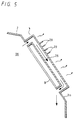
- FIG. 5 shows a modification of the heat radiating means to be provided in the housing 2.
- the heat radiating means is a radiator 28 attached to the tilted wall 2a of the housing 2.
- the radiator 28 is formed like a pipe and attached to the tilted wall 2a of the housing 2 so that the both ends thereof communicates with the space 26.
- the above-mentioned radiator 28 is exposed to the outside of the housing 2, it has a large surface area contacting with outside air and thereby, it is able to efficiently discharge the heat. Moreover, as illustrated, by attaching radiating fins 29, 29,... to the surface of the radiator 28, it is possible to further increase the radiation effect.
- FIG. 6 shows a second embodiment obtained by applying the present invention to a liquid-crystal projector system so as to restrict the flow of the air reaching the upper portion of a space 26 up to a path 25.
- a pipe-shaped radiator 30 is disposed inside a tilted portion 2a of a housing 2 so as to contact with the outside air.
- Portions of the housing 2 with which a mirror 9 contacts, that is, the tilted portion 2a and a portion communicating with the upperside of the tilted portion 2a (portion provided with a translucent pattern in FIG. 6) are made of a material having a high heat conductivity such as a metal or the like.
- a partition wall 31 having a cylindrical rib for surrounding the outside of a cylindrical support portion is provided between the exit 30b of the radiator 30 and the upperside opening 25a of the path 25 so that the exit 30b of the radiator 30 is communicated with the upperside opening 25a of the path 25 in a closed state.
- an air-flow restriction path is formed from the entrance 30a of the radiator 30 up to the opening 12a of a duct 12 of the optical block 6 through the upperside opening 25a of the path 25 and the path 25.
- the air heated in the optical block 6 is exhausted to the space 26 of the housing 2 by an air flow generated by a fan 27 provided in the optical block 6 and moreover, moved to the upper portion of the space 26, and radiated at the upper portion of the housing 2, and enters the radiator 30.
- the air entering the radiator 30 is cooled while passing through the radiator 30 and then, enters the optical block 6 through the path 25 after passing through the duct 12 again.
- the airflow is restricted so that the heated air passes through the radiator 30 without failure and enters the optical block 6 again.
- the air exhausted into the space 26 from the optical block 6 does not return to the optical block 6 again without passing through the radiator 30, the air once exhausted from the optical block 6 always enters the optical block 6 through the cooling step for passing through the radiator 30 and thereby, a temperature rise of optical components in the optical block 6 is securely suppressed.
- the dust collector 32 mentioned above can be removed for cleaning and set to the predetermined position after cleaning again.
- the radiator 30 can be disposed so as to contact with the mirror 9 as shown in FIG. 7.
- the spaces 26 of the liquid-crystal projector systems 1 and 1A can be formed into a closed structure, it is possible to prevent any dust from entering the spaces 26 and the optical block 6 from the outside.
- the optical block 6 is located in the closed space 26, it is possible to prevent fan noises from leaking to the outside even if the fan 27 is used.
- FIG. 8 shows a third embodiment constituted by applying the present invention to a liquid-crystal projector system.
- the liquid-crystal projector system 1B of this embodiment is provided with means for directly discharging the heat of an optical block 6 to the outside of a housing 2.
- a radiator 33 constituted by a material superior in heat conductivity is provided to the front lower portion of the housing 2 so as to be exposed and the radiator 33 and the case 10 of the optical block 6 are connected with each other by a conductive member 34 superior in heat conductivity such as a heat-pipe or the like.
- a conductive member 34 superior in heat conductivity such as a heat-pipe or the like.
- the screen 3 is located in the housing 2.
- a structure in which a screen is set outside of a closed structure and attached to the front of a display unit is also permitted to use.
- the present invention makes it possible to separately provide the first cooling means for cooling the light source 5 and the second cooling means for cooling the optical block 6 and thereby, use optimum cooling means respectively corresponding to the light source 5 and the optical block 6, and independently perform cooling without receiving an influence of mutual cooling means.
- the means shown in FIG. 9 is provided with a duct 36 through which cooling air passes along a surrounding wall 35 surrounding the light source 5 such as a halogen lamp or the like.
- the light source 5 is cooled by circulating the cooling air through the duct 36 in accordance with natural convection or forced circulation by air-flow generating means such as a fan or the like.
- the above-mentioned surrounding wall 35 is opened at the side from which the light emitted from the light source 5 is emitted.
- the means shown in FIG. 10 is constituted by connecting an intake duct 37 and an exhaust duct 38 to a fixing member 39 fixing the surrounding wall 35.
- the cooling air is circulated through the ducts 37 and 38 in accordance with natural convection or forced circulation by the airflow generating means such as a fan or the like.
- the above fixing member 39 is made of a heat-resistant molding resin or the like and has almost-rectangular openings 39a and 39a at its side so that air can be supplied to the surrounding wall 35 through the openings 39a and 39a.
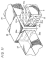
- the surrounding wall 35 has a plurality of openings 35a, 35a,... (refer to FIG. 11) and thereby, it is possible to supply the air incoming from the openings 39a and 39a of the fixing member 39 to the light source 5 through the openings 35a, 35a,....
- the light-source section including the surrounding wall 35 can be attached to or detached from the fixing member 39 (FIG. 11 shows such a state that the light-source section is taken out of the fixing member) and thereby, it is possible to easily replace the light source 5.
- the fixing member 39 it is permitted to constitute the fixing member 39 so as to have the opening 39a at the side face opposite to the illustrated side face. Furthermore, it is permitted to use only the intake duct 37 so that the air is exhausted through the openings 35a, 35a,... of the surrounding wall 35 and the openings 39a and 39a of the fixing member 39.
- the first cooling means for cooling the light source 5 it is possible to constitute proper cooling means corresponding to the light source 5 and optical block 6 which are greatly different from each other in calorific value as compared with the case where the light source 5 and the optical block 6 are cooled by the same cooling means.
- the light source 5 is less influenced by attachment of dust than the optical block 6 is, it is not always necessary to close the light-source section and it is enough for the first cooling means to have the above-described simple structure.
Landscapes
- Physics & Mathematics (AREA)
- General Physics & Mathematics (AREA)
- Engineering & Computer Science (AREA)
- Mechanical Engineering (AREA)
- Projection Apparatus (AREA)
- Devices For Indicating Variable Information By Combining Individual Elements (AREA)
- Liquid Crystal (AREA)
Abstract
Description
- The present invention relates to a new display unit, and particularly to an article for effectively performing cooling without destroying a closed environment.
- For example, in the case of a liquid-crystal projector system for displaying an image by irradiating the light emitted from a light source onto a liquid-crystal light bulb and projecting the light passing through the liquid-crystal light bulb on a screen by a projection lens, various cooling methods have been used so far in order to prevent temperatures of the liquid-crystal light bulb and various optical components from rising due to the heat of the light source.
- For example, there is a method of performing the cooling by supplying outside air into the housing of the liquid-crystal projector system by using a fan.
- However, a method of cooling a housing by supplying outside air into the housing by a fan has a problem that not only the outside air but also dust are taken in at the same time and the dust attaches to a liquid-crystal light bulb and various optical component.
- As a result, a problem occurs that the dust interrupts or diffuses the transmitted light of the liquid-crystal light bulb and thereby, stains or bleeding is produced on an image.
- Therefore, in order to prevent the attachment of the dust, it is generally carried out that a dust-removing filter is attached to an outside-air intake.
- However, even if the dust-removing filter is attached, it is impossible to remove dust smaller than the mesh of the filter. Therefore, a problem occurs that fine dust accumulates in the liquid-crystal projector system and dust attaches to the liquid-crystal light bulb and the various optical components in any case.
- Moreover, in the case of this method, a problem occurs that the filter must be frequently cleaned although the filter is incomplete as dust-removing means.
- Furthermore, when using a fan, the fan emits noises to the outside of the housing of the liquid-crystal projector system. Therefore, a problem occurs that unnecessary noises other than voices are produced while operating the liquid-crystal projector system and cause a user or audience to feel an uncomfortable sense.
- Furthermore, a method of constituting an optical block including a liquid-crystal light bulb into a closed type in a liquid-crystal projector system and circulating air into the inside of the optical block is considered as a cooling method other than the above method.
- To use the above method, however, there is a problem that it is necessary to improve the radiating performance of the closed optical block because the air capacity in the optical block is small and thus the structure of the liquid-crystal projector system has necessarily to be complex.
- Therefore, it is an aim of the present invention to prevent dust from entering a system and attaching to optical components as well as to sufficiently cool the heat produced in the system.
- Accordingly, the present invention provides a display unit, comprising a housing having a screen at its front and constituted by a closed structure, an optical block set in the closed housing, and connecting means for connecting the housing with the optical block to circulate air.
- With this construction, the display unit of the present invention makes it possible to cool the optical block by circulating air between the housing and the optical block through the connecting means and cooling the air during its circulation. Moreover, because the optical block is located in the closed housing, dust does not enter the optical block from the outside.
- The present invention also provides a display unit, comprising a housing having a screen at its front and constituted by a closed structure, an optical block set in the closed housing, first cooling means for cooling a light source, and second cooling means for cooling the optical block.
- As it is possible to separately use the first cooling means and the second cooling means corresponding respectively to the light source and the optical block, it is possible to use proper cooling means corresponding to the light source and the optical block where greatly different from each other in calorific value. Therefore, it is possible to improve the cooling efficiencies of the light source and the optical block, and moreover, more preferably constitute the display unit because the degrees of freedom in the design of the light source and the optical block are increased.
- Preferred embodiments of the present invention will now be described hereinbelow by way of example only with reference to the accompanying drawings, in which:
- FIG. 1 is a longitudinal sectional view of a first embodiment obtained by applying the present invention to a liquid-crystal projector system together with FIGS. 2 to 4;
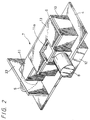
- FIG. 2 is a perspective view of an optical-system-constituting unit;
- FIG. 3 is an illustration showing a configuration of an optical system of an optical block;
- FIG. 4 is a sectional view showing an essential portion of an optical-system-constituting unit;
- FIG. 5 is a sectional view of an essential portion showing a modification of heat radiating means;
- FIG. 6 is a longitudinal sectional view showing a second embodiment obtained by applying the present invention to a liquid-crystal projector system;
- FIG. 7 is a sectional view of an essential portion showing a modification of a method for attaching a radiator;
- FIG. 8 is a longitudinal sectional view showing a third embodiment obtained by applying the present invention to a liquid-crystal projector system;
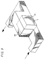
- FIG. 9 is a perspective view showing means for cooling a light source;
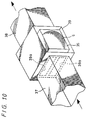
- FIG. 10 is a perspective view showing another example of the means for cooling the light source; and
- FIG. 11 is a perspective view showing a modification of the means in FIG. 10.
-
- Embodiments of display units of the present invention are described below by referring to the accompanying drawings. The embodiments shown in the accompanying drawings are those obtained by applying the present invention to a liquid-crystal projector system.
- FIGS. 1 to 4 show a first embodiment of a display unit according to the present invention.
- A liquid-
crystal projector system 1 is provided with ahousing 2 having a closed structure, in which ascreen 3 is located at the front of thehousing 2 and an optical-system-constitutingunit 7 obtained by arranging alight source 5 and anoptical block 6 on asubstrate 4 is located at the lower portion in thehousing 2. - The light projected from a
projection lens 8 of theoptical block 6 is reflected by amirror 9 diposed at the back side in thehousing 2 and advanced to thescreen 3 at the front side. - As shown in FIG. 2, the optical-system-constituting
unit 7 is constituted by arranging thelight source 5 and theoptical block 6 on thesubstrate 4. - The
optical block 6 is provided with acase 10 and alid 11 for closing the upperside of thecase 10 and aduct 12 is provided below the front end of thecase 10 so that the inside of thecase 10 communicates with theduct 12. Moreover, theduct 12 has an opening 12a. Then, optical components are stored in thecase 10 and adriving circuit 13 for driving a liquid-crystal light bulb to be described later is formed on thelid 11. Furthermore, an opening 11a is formed on thelid 11 so as to be able to perform registration of the liquid-crystal light bulb, that is, overlapping adjustment of an image through the opening 11a. - The
optical block 6 moreover has the internal configuration shown in FIG. 3. That is,lens arrays light source 5 and moreover,dichroic mirrors 15a and 15b andreflectors light source 5 into three color lights of red, green, and blue (R, G, and B) and guiding them to the liquid crystal are arranged. Moreover, condensers 17a, 17b, and 17c, polarizingplates crystal light bulbs prism 20 at the rear stage. Furthermore, aprojection lens 8 for projecting a synthesized light is provided at the rear stage of the light-synthesizingprism 20. - A
partition wall 23 is provided between thecase 10 and thelight source 5 to interrupt the space between thelight source 5 serving as a heat source and theoptical block 6. - The above-mentioned
optical block 6 operates as described below. - The light emitted from the
light source 5 such as a metal halide lamp or the like passes through acut filter 21 for cutting off ultraviolet and infrared rays and enters theoptical block 6. Thecut filter 21 also has a function for closing thecase 10 of theoptical block 6. - The light entering the
optical block 6 passes through thelens arrays condenser 17a and the polarizingplate 18a, and moreover passes through the red liquid-crystal light bulb 19a. - Of green light G and blue light B passing through the dichroic mirror 15a, the green light G is separated and reflected by the
dichroic mirror 15b, passes through thecondenser 17b and the polarizingplate 18b, and moreover passes through the green liquid-crystal light bulb 19b. - Moreover the blue light B passing through the
dichroic mirror 15b is reflected by thereflectors condenser 17c and the polarizingplate 18c, and moreover passes through the blue liquid-crystal light bulb 19c. In the figure,symbols 22a and 22b denote relay lens. - Then, the lights passing through the liquid-
crystal light bulbs prism 20 where the lights are synthesized, and the synthesized light is enlarged and projected on thescreen 3 by theprojection lens 8. Thus, an image is displayed on thescreen 3 by theoptical block 6. - Then, a mechanism for cooling the
optical block 6 will be explained below. - As described above, the optical-
system constituting unit 7 is located at the front lower portion of thehousing 2, a closed path-formingsection 24 is provided at the rear lower-half portion of thehousing 2, apath 25 formed on the path-formingsection 24 opens at the upside and at the front lower portion of the path-formingsection 24, an upside opening 25a communicates with alarge space 26 of thehousing 2, and an opening 25b at the front lower portion is connected with the opening 12a of theduct 12 of theoptical block 6 in a closed state. - Moreover, a
fan 27 is disposed in theduct 12 of theoptical block 6. - When the above-described liquid-crystal projector system operates, the light emitted from the
light source 5 heats the three-color liquid-crystal light bulbs plates optical block 6, the air heated by the heat radiation from these optical components is exhausted from the opening 11a to thespace 26 of thehousing 2 through the forced circulation by thefan 27 provided in theduct 12 of theoptical block 6. - As the air-flow generating means, it is also permitted to use not only the means for performing the forced circulation such as the above-mentioned
fan 27 but also the natural convection that lightweight air heated in thecase 10 of theoptical block 6 goes into thespace 26 from the opening 11a and new air comes in from the opening 12a of theduct 12 instead and thereby the air circulation is naturally generated. - Then, the heated air is exhausted to the
large space 26 as described above and thereby, the heat of the air diffuses in theentire space 26 and moreover, it is exhausted to the outside through the housing 2 (mainly from the upside and back). Therefore, by forming the whole or a part of thehousing 2 such as atilted portion 2a of thehousing 2 facing themirror 9 with a material having a high heat conductivity such as a metal or the like, it is possible to increase the radiation effect. Moreover, by providing a fin for radiation to theportion 2a or other portions, it is possible to further increase the radiation effect. - Then, as described above, the cooled air circulates so that the air enters the
case 10 of theoptical block 6 through theduct 12 after passing through thepath 25 from thespace 26, cools the liquid-crystal light bulbs plates space 26 through the opening 11a (refer to arrows in FIG. 1). - In the case of the
optical block 6, a gap is formed between thereflectors condensers polarizing plates crystal light bulbs prism 20 so that air can pass through the gaps and thereby, these optical components are effectively cooled. - FIG. 5 shows a modification of the heat radiating means to be provided in the
housing 2. - The heat radiating means is a
radiator 28 attached to the tiltedwall 2a of thehousing 2. Theradiator 28 is formed like a pipe and attached to the tiltedwall 2a of thehousing 2 so that the both ends thereof communicates with thespace 26. - Because the above-mentioned
radiator 28 is exposed to the outside of thehousing 2, it has a large surface area contacting with outside air and thereby, it is able to efficiently discharge the heat. Moreover, as illustrated, by attaching radiatingfins radiator 28, it is possible to further increase the radiation effect. - FIG. 6 shows a second embodiment obtained by applying the present invention to a liquid-crystal projector system so as to restrict the flow of the air reaching the upper portion of a
space 26 up to apath 25. - In the case of the liquid-crystal projector system 1A according to the second embodiment, a pipe-shaped
radiator 30 is disposed inside a tiltedportion 2a of ahousing 2 so as to contact with the outside air. Portions of thehousing 2 with which amirror 9 contacts, that is, the tiltedportion 2a and a portion communicating with the upperside of the tiltedportion 2a (portion provided with a translucent pattern in FIG. 6) are made of a material having a high heat conductivity such as a metal or the like. - Moreover, in order to prevent the air cooled after passing through the
radiator 30 from mixing with the air heated by anoptical block 6 and exhausted into aspace 26, apartition wall 31 having a cylindrical rib for surrounding the outside of a cylindrical support portion is provided between theexit 30b of theradiator 30 and theupperside opening 25a of thepath 25 so that theexit 30b of theradiator 30 is communicated with theupperside opening 25a of thepath 25 in a closed state. Thereby, an air-flow restriction path is formed from theentrance 30a of theradiator 30 up to theopening 12a of aduct 12 of theoptical block 6 through theupperside opening 25a of thepath 25 and thepath 25. - Thus, the air heated in the
optical block 6 is exhausted to thespace 26 of thehousing 2 by an air flow generated by afan 27 provided in theoptical block 6 and moreover, moved to the upper portion of thespace 26, and radiated at the upper portion of thehousing 2, and enters theradiator 30. - The air entering the
radiator 30 is cooled while passing through theradiator 30 and then, enters theoptical block 6 through thepath 25 after passing through theduct 12 again. - As described above, the airflow is restricted so that the heated air passes through the
radiator 30 without failure and enters theoptical block 6 again. Thereby, the air exhausted into thespace 26 from theoptical block 6 does not return to theoptical block 6 again without passing through theradiator 30, the air once exhausted from theoptical block 6 always enters theoptical block 6 through the cooling step for passing through theradiator 30 and thereby, a temperature rise of optical components in theoptical block 6 is securely suppressed. - Moreover, it is possible to locate a dust collector in the airflow restriction path or in the middle of the
path 25. Thereby, it is possible to remove dust in the liquid-crystal projector 1A. - No dust enters the
housing 2 and theoptical block 6 having a closed structure from the outside and it is possible to remove dust by thedust collector 32, which has entered thespace 26 and a space of theoptical block 6 while the liquid-crystal projector system 1A is being manufactured as well as to completely eliminate an influence of the dust on an image. - It is preferable that the
dust collector 32 mentioned above can be removed for cleaning and set to the predetermined position after cleaning again. - The
radiator 30 can be disposed so as to contact with themirror 9 as shown in FIG. 7. - Moreover, it is possible to provide a plurality of the
radiators housing 2. Thus, it is possible to further improve the radiation efficiency. - According to each of the above embodiments, because the
spaces 26 of the liquid-crystal projector systems 1 and 1A can be formed into a closed structure, it is possible to prevent any dust from entering thespaces 26 and theoptical block 6 from the outside. - Moreover, because the
optical block 6 is located in the closedspace 26, it is possible to prevent fan noises from leaking to the outside even if thefan 27 is used. - Furthermore, it is possible to improve endothermic and heat radiation effects of the
housing 2 by using a material superior in heat conductivity and heat radiation such as a metal or the like for thehousing 2. - Furthermore, it is possible to improve endothermic and heat radiation effects of the
case 10 of theoptical block 6 by using a material superior in heat conductivity and heat radiation such as a metal or the like for thecase 10 of theoptical block 6 and thereby, further efficiently discharge heat in theoptical block 6 to thespace 26. - FIG. 8 shows a third embodiment constituted by applying the present invention to a liquid-crystal projector system. The liquid-crystal projector system 1B of this embodiment is provided with means for directly discharging the heat of an
optical block 6 to the outside of ahousing 2. - That is, a
radiator 33 constituted by a material superior in heat conductivity is provided to the front lower portion of thehousing 2 so as to be exposed and theradiator 33 and thecase 10 of theoptical block 6 are connected with each other by aconductive member 34 superior in heat conductivity such as a heat-pipe or the like. Thereby, the heat produced in theoptical block 6 and conducted to thecase 10 is radiated to the outside of thehousing 2 by theradiator 33 through theconductive member 34. - Though the above configurations individually have an effect, it is also possible to use a plurality of the configurations by combining them.
- Moreover, in the case of the liquid-
crystal projector systems 1, 1A, and 1B, thescreen 3 is located in thehousing 2. However, it is also permitted to use a structure in which a screen is set outside of a closed structure and attached to the front of a display unit. - Furthermore, the present invention makes it possible to separately provide the first cooling means for cooling the
light source 5 and the second cooling means for cooling theoptical block 6 and thereby, use optimum cooling means respectively corresponding to thelight source 5 and theoptical block 6, and independently perform cooling without receiving an influence of mutual cooling means. - It is possible to use each of the cooling means described above as the second cooling means for cooling the
optical block 6. - Moreover, it is possible to use each of means to be described later as the first cooling means for cooling the
light source 5. - The means shown in FIG. 9 is provided with a
duct 36 through which cooling air passes along a surroundingwall 35 surrounding thelight source 5 such as a halogen lamp or the like. - Moreover, the
light source 5 is cooled by circulating the cooling air through theduct 36 in accordance with natural convection or forced circulation by air-flow generating means such as a fan or the like. - The above-mentioned surrounding
wall 35 is opened at the side from which the light emitted from thelight source 5 is emitted. - The means shown in FIG. 10 is constituted by connecting an
intake duct 37 and anexhaust duct 38 to a fixingmember 39 fixing the surroundingwall 35. - Then, the cooling air is circulated through the
ducts - The above fixing
member 39 is made of a heat-resistant molding resin or the like and has almost-rectangular openings wall 35 through theopenings - Moreover, the surrounding
wall 35 has a plurality ofopenings openings member 39 to thelight source 5 through theopenings - In the case of the above configuration, the light-source section including the surrounding
wall 35 can be attached to or detached from the fixing member 39 (FIG. 11 shows such a state that the light-source section is taken out of the fixing member) and thereby, it is possible to easily replace thelight source 5. - Moreover, it is permitted to constitute the fixing
member 39 so as to have theopening 39a at the side face opposite to the illustrated side face. Furthermore, it is permitted to use only theintake duct 37 so that the air is exhausted through theopenings wall 35 and theopenings member 39. - As described above, by providing the first cooling means for cooling the
light source 5, it is possible to constitute proper cooling means corresponding to thelight source 5 andoptical block 6 which are greatly different from each other in calorific value as compared with the case where thelight source 5 and theoptical block 6 are cooled by the same cooling means. - Therefore, it is possible to improve each of the cooling efficiency of the
light source 5 as well as theoptical block 6. - Moreover, to increase degrees of freedom of design of the
light source 5 andoptical block 6, it is possible to more preferably constitute a display unit by considering various conditions such as operation costs including the manufacturing cost and power consumption of a display unit or the like. - Furthermore, because the
light source 5 is less influenced by attachment of dust than theoptical block 6 is, it is not always necessary to close the light-source section and it is enough for the first cooling means to have the above-described simple structure. - The shape and structure of each section shown for each embodiment described above only represent examples for embodying the present invention. Therefore, the scope of the present invention must not be understood as being so limited.
- Having described preferred embodiments of the present invention with reference to the accompanying drawings, it is to be understood that the present invention is not limited to the above-mentioned embodiments and that various changes and modifications can be effected therein by one skilled in the art without departing from the scope of the present invention as defined by the appended claims.
Claims (11)
- A display unit, comprising:a housing having a screen at its front and constituted by a closed structure;an optical block set in the closed housing; andconnecting means for connecting the housing with the optical block to circulate air.
- The display unit according to claim 1, whereinheat radiating means for radiating the heat of heated air to the outside through the housing is provided.
- The display unit according to claim 2, whereinthe heat radiating means is formed by a good heat-conductive member constituting the housing.
- The display unit according to claim 2, whereinthe heat radiating means is constituted by a pipe body communicating with an internal space of the housing so as to contact with outside air.
- The display unit according to Claim 4, wherein a heat radiating fin is attached to the pipe body.
- The display unit according to claim 1, wherein the housing is provided with an air-flow restriction path for restricting the flow of air circulating through the housing.
- The display unit according to Claim 6, whereina dust collector is provided upstream of the air-flow restriction path.
- The display unit according to claim 1, whereinheat radiating means for exhausting heated air to the inside or outside of a closed space through the Optical block is provided.
- The display unit according to claim 8, whereinthe heat radiating means is formed by a good heat-conductive member constituting the optical block.
- A display unit, comprising:a housing having a screen at its front and Constituted by a closed structure;an optical block set in the closed housing;first cooling means for cooling a light source; andsecond cooling means for cooling the optical block.
- The display unit according to claim 10, whereinconnecting means for circulating air is provided between the optical block and the housing.
Applications Claiming Priority (2)
| Application Number | Priority Date | Filing Date | Title |
|---|---|---|---|
| JP9072099 | 1999-03-31 | ||
| JP11090720A JP2000284701A (en) | 1999-03-31 | 1999-03-31 | Display device |
Publications (2)
| Publication Number | Publication Date |
|---|---|
| EP1041431A2 true EP1041431A2 (en) | 2000-10-04 |
| EP1041431A3 EP1041431A3 (en) | 2003-07-23 |
Family
ID=14006396
Family Applications (1)
| Application Number | Title | Priority Date | Filing Date |
|---|---|---|---|
| EP00302603A Ceased EP1041431A3 (en) | 1999-03-31 | 2000-03-29 | Image projector with cooling means |
Country Status (5)
| Country | Link |
|---|---|
| US (1) | US6450646B1 (en) |
| EP (1) | EP1041431A3 (en) |
| JP (1) | JP2000284701A (en) |
| KR (1) | KR100749287B1 (en) |
| MY (1) | MY125192A (en) |
Cited By (2)
| Publication number | Priority date | Publication date | Assignee | Title |
|---|---|---|---|---|
| GB2414085A (en) * | 2004-05-12 | 2005-11-16 | Samsung Electronics Co Ltd | Image projection apparatus with air cooling |
| WO2007061079A3 (en) * | 2005-11-22 | 2008-01-24 | Casio Computer Co Ltd | Projector system having cooling fan |
Families Citing this family (26)
| Publication number | Priority date | Publication date | Assignee | Title |
|---|---|---|---|---|
| JP2002006394A (en) * | 2000-06-26 | 2002-01-09 | Olympus Optical Co Ltd | Multi-display device |
| US6565214B1 (en) * | 2000-08-31 | 2003-05-20 | Mitsubishi Digital Electronics America, Inc. | Enclosure for projection television sets |
| EP1193982A1 (en) * | 2000-09-20 | 2002-04-03 | Barco N.V. | Projector with system for cooling the light modulators |
| US6840629B2 (en) * | 2000-11-14 | 2005-01-11 | Yamaha Corporation | Ventilating structure and mounting structure for electronic apparatus |
| KR100434170B1 (en) * | 2001-05-15 | 2004-06-04 | 엘지전자 주식회사 | Cooling structure for projection television |
| JP2003152375A (en) * | 2001-11-16 | 2003-05-23 | Sanyo Electric Co Ltd | Display and liquid crystal projector |
| JP4100012B2 (en) * | 2002-03-13 | 2008-06-11 | セイコーエプソン株式会社 | Rear projector |
| JP2003337377A (en) * | 2002-03-13 | 2003-11-28 | Seiko Epson Corp | Rear projector |
| JP2004294781A (en) * | 2003-03-27 | 2004-10-21 | Seiko Epson Corp | Cooling structure of projection TV |
| US7334898B2 (en) * | 2003-10-10 | 2008-02-26 | Seiko Epson Corporation | Projector |
| JP4192882B2 (en) * | 2003-12-26 | 2008-12-10 | セイコーエプソン株式会社 | Optical device and projector |
| KR100588147B1 (en) * | 2004-05-10 | 2006-06-09 | 삼성전자주식회사 | Projection television |
| JP4056504B2 (en) * | 2004-08-18 | 2008-03-05 | Necディスプレイソリューションズ株式会社 | COOLING DEVICE AND ELECTRONIC DEVICE HAVING THE SAME |
| JP2006098887A (en) * | 2004-09-30 | 2006-04-13 | Orion Denki Kk | Rear projection television |
| JP4659466B2 (en) * | 2005-01-25 | 2011-03-30 | キヤノン株式会社 | Projection display |
| JP4428242B2 (en) * | 2005-01-28 | 2010-03-10 | セイコーエプソン株式会社 | Rear projector |
| KR100699259B1 (en) * | 2005-03-08 | 2007-03-27 | 삼성전자주식회사 | Display device |
| JP2006349868A (en) * | 2005-06-14 | 2006-12-28 | Sony Corp | Projection television equipment |
| JP4650681B2 (en) * | 2005-08-16 | 2011-03-16 | ソニー株式会社 | Lighting device and image display device |
| WO2009119442A1 (en) * | 2008-03-25 | 2009-10-01 | 日本電気株式会社 | Liquid crystal display device |
| CN102568986A (en) * | 2011-10-31 | 2012-07-11 | 上海显恒光电科技股份有限公司 | Low-power-consumption laser cathode ray tube (CRT) based on laminar flow electronic gun, and projection system |
| JP6919819B2 (en) * | 2018-12-18 | 2021-08-18 | カシオ計算機株式会社 | Cooling device, light source device and projection device |
| JP7394586B2 (en) * | 2019-11-01 | 2023-12-08 | リコーインダストリアルソリューションズ株式会社 | image projection device |
| CN114253059A (en) * | 2020-09-25 | 2022-03-29 | 中强光电股份有限公司 | Optical machine module and projector |
| CN116339057B (en) * | 2021-12-22 | 2026-01-13 | 中强光电股份有限公司 | Projection lens module |
| CN114777036B (en) * | 2022-05-23 | 2024-09-03 | 弘宇灯饰(深圳)有限公司 | Integrated LED lamp favorable for heat dissipation |
Citations (2)
| Publication number | Priority date | Publication date | Assignee | Title |
|---|---|---|---|---|
| JPH1141547A (en) * | 1997-07-22 | 1999-02-12 | Matsushita Electric Ind Co Ltd | Rear projection device |
| EP0949535A1 (en) * | 1998-04-06 | 1999-10-13 | Sony Corporation | Display apparatus and its cooling method |
Family Cites Families (11)
| Publication number | Priority date | Publication date | Assignee | Title |
|---|---|---|---|---|
| US1954786A (en) * | 1931-03-12 | 1934-04-17 | James J Bright | Stray light eliminating and picture cabinet enlarging device |
| JPH04147291A (en) * | 1990-10-11 | 1992-05-20 | Matsushita Electric Ind Co Ltd | Cooling control device |
| US5278596A (en) * | 1992-05-19 | 1994-01-11 | Machtig Jeffrey S | LCD projection apparatus |
| JP2986297B2 (en) * | 1992-12-28 | 1999-12-06 | 日本信号株式会社 | LED display |
| US5808704A (en) * | 1994-01-17 | 1998-09-15 | Hitachi, Ltd. | Rear projection type image display apparatus |
| JP3659271B2 (en) * | 1995-10-03 | 2005-06-15 | ソニー株式会社 | Rear projection video device |
| EP0939333A4 (en) * | 1996-10-31 | 2003-05-14 | Sanyo Electric Co | Back projection display |
| JPH10254060A (en) * | 1997-03-10 | 1998-09-25 | Sanyo Electric Co Ltd | Back projection type display device |
| JP3313995B2 (en) * | 1997-02-10 | 2002-08-12 | 株式会社日立製作所 | Video display device |
| US6394608B1 (en) * | 1997-06-20 | 2002-05-28 | Hitachi, Ltd. | Display device and display optical system unit |
| JP2001222066A (en) * | 2000-02-09 | 2001-08-17 | Sony Corp | Projector device |
-
1999
- 1999-03-31 JP JP11090720A patent/JP2000284701A/en active Pending
-
2000
- 2000-03-23 MY MYPI20001149A patent/MY125192A/en unknown
- 2000-03-29 EP EP00302603A patent/EP1041431A3/en not_active Ceased
- 2000-03-29 US US09/537,889 patent/US6450646B1/en not_active Expired - Fee Related
- 2000-03-29 KR KR1020000016039A patent/KR100749287B1/en not_active Expired - Fee Related
Patent Citations (2)
| Publication number | Priority date | Publication date | Assignee | Title |
|---|---|---|---|---|
| JPH1141547A (en) * | 1997-07-22 | 1999-02-12 | Matsushita Electric Ind Co Ltd | Rear projection device |
| EP0949535A1 (en) * | 1998-04-06 | 1999-10-13 | Sony Corporation | Display apparatus and its cooling method |
Cited By (3)
| Publication number | Priority date | Publication date | Assignee | Title |
|---|---|---|---|---|
| GB2414085A (en) * | 2004-05-12 | 2005-11-16 | Samsung Electronics Co Ltd | Image projection apparatus with air cooling |
| GB2414085B (en) * | 2004-05-12 | 2006-08-02 | Samsung Electronics Co Ltd | Image projection apparatus with air cooling |
| WO2007061079A3 (en) * | 2005-11-22 | 2008-01-24 | Casio Computer Co Ltd | Projector system having cooling fan |
Also Published As
| Publication number | Publication date |
|---|---|
| JP2000284701A (en) | 2000-10-13 |
| MY125192A (en) | 2006-07-31 |
| US6450646B1 (en) | 2002-09-17 |
| EP1041431A3 (en) | 2003-07-23 |
| KR20000063044A (en) | 2000-10-25 |
| KR100749287B1 (en) | 2007-08-14 |
Similar Documents
| Publication | Publication Date | Title |
|---|---|---|
| US6450646B1 (en) | Display unit | |
| KR100358621B1 (en) | Liquid Crystal Projection Apparatus and Lamp | |
| EP2085819B1 (en) | Projector and cooling system | |
| US6462804B1 (en) | Display apparatus and its cooling method | |
| CN100498513C (en) | Cooling apparatus and a projector having the same | |
| JP5561401B2 (en) | projector | |
| KR20000056980A (en) | Display optical unit and display apparatus using this unit | |
| JPH10221779A (en) | Video display device | |
| JP2003057754A (en) | Cooling device and projector having the same | |
| JP2000269674A (en) | LCD projector | |
| CN205787555U (en) | Projector | |
| JP4572158B2 (en) | Projection display | |
| JP4142161B2 (en) | Spot light source device | |
| JP2000305470A (en) | Display device | |
| US6945655B1 (en) | Convection cooled light projector | |
| JP2004004942A (en) | Projector apparatus | |
| KR200151071Y1 (en) | Cooling assembly for projector | |
| CN223711994U (en) | Projection display device | |
| JP4099037B2 (en) | LCD projector | |
| JP2002150832A (en) | Projection display device | |
| JP2004133304A (en) | Projection display device | |
| KR19990020543U (en) | Heat dissipation structure for the projector | |
| JP2008191531A (en) | Rear projector | |
| JP2004101676A (en) | projector | |
| JP2003084362A (en) | Projector |
Legal Events
| Date | Code | Title | Description |
|---|---|---|---|
| PUAI | Public reference made under article 153(3) epc to a published international application that has entered the european phase |
Free format text: ORIGINAL CODE: 0009012 |
|
| AK | Designated contracting states |
Kind code of ref document: A2 Designated state(s): AT BE CH CY DE DK ES FI FR GB GR IE IT LI LU MC NL PT SE |
|
| AX | Request for extension of the european patent |
Free format text: AL;LT;LV;MK;RO;SI |
|
| PUAL | Search report despatched |
Free format text: ORIGINAL CODE: 0009013 |
|
| AK | Designated contracting states |
Designated state(s): AT BE CH CY DE DK ES FI FR GB GR IE IT LI LU MC NL PT SE |
|
| AX | Request for extension of the european patent |
Extension state: AL LT LV MK RO SI |
|
| RIC1 | Information provided on ipc code assigned before grant |
Ipc: 7H 04N 9/31 B Ipc: 7G 03B 21/16 B Ipc: 7G 03B 21/10 A |
|
| 17P | Request for examination filed |
Effective date: 20040112 |
|
| 17Q | First examination report despatched |
Effective date: 20040212 |
|
| AKX | Designation fees paid |
Designated state(s): DE ES FR GB IT |
|
| 17Q | First examination report despatched |
Effective date: 20040212 |
|
| STAA | Information on the status of an ep patent application or granted ep patent |
Free format text: STATUS: THE APPLICATION HAS BEEN REFUSED |
|
| 18R | Application refused |
Effective date: 20080424 |