EP1041429A1 - Memory module reader for memory modules used with film cassettes - Google Patents
Memory module reader for memory modules used with film cassettes Download PDFInfo
- Publication number
- EP1041429A1 EP1041429A1 EP00201013A EP00201013A EP1041429A1 EP 1041429 A1 EP1041429 A1 EP 1041429A1 EP 00201013 A EP00201013 A EP 00201013A EP 00201013 A EP00201013 A EP 00201013A EP 1041429 A1 EP1041429 A1 EP 1041429A1
- Authority
- EP
- European Patent Office
- Prior art keywords
- memory module
- module
- cam
- memory
- reader
- Prior art date
- Legal status (The legal status is an assumption and is not a legal conclusion. Google has not performed a legal analysis and makes no representation as to the accuracy of the status listed.)
- Withdrawn
Links
- 230000000717 retained effect Effects 0.000 claims abstract description 5
- ZZUFCTLCJUWOSV-UHFFFAOYSA-N furosemide Chemical group C1=C(Cl)C(S(=O)(=O)N)=CC(C(O)=O)=C1NCC1=CC=CO1 ZZUFCTLCJUWOSV-UHFFFAOYSA-N 0.000 claims 1
- 230000000295 complement effect Effects 0.000 description 2
- 238000004519 manufacturing process Methods 0.000 description 2
- 239000011230 binding agent Substances 0.000 description 1
- 230000000694 effects Effects 0.000 description 1
- 238000003780 insertion Methods 0.000 description 1
- 230000037431 insertion Effects 0.000 description 1
- 238000009434 installation Methods 0.000 description 1
- 239000007937 lozenge Substances 0.000 description 1
- 239000000463 material Substances 0.000 description 1
- 239000002184 metal Substances 0.000 description 1
- 238000004382 potting Methods 0.000 description 1
- 238000007493 shaping process Methods 0.000 description 1
Images





Classifications
-
- G—PHYSICS
- G03—PHOTOGRAPHY; CINEMATOGRAPHY; ANALOGOUS TECHNIQUES USING WAVES OTHER THAN OPTICAL WAVES; ELECTROGRAPHY; HOLOGRAPHY
- G03B—APPARATUS OR ARRANGEMENTS FOR TAKING PHOTOGRAPHS OR FOR PROJECTING OR VIEWING THEM; APPARATUS OR ARRANGEMENTS EMPLOYING ANALOGOUS TECHNIQUES USING WAVES OTHER THAN OPTICAL WAVES; ACCESSORIES THEREFOR
- G03B7/00—Control of exposure by setting shutters, diaphragms or filters, separately or conjointly
- G03B7/24—Control of exposure by setting shutters, diaphragms or filters, separately or conjointly automatically in accordance with markings or other means indicating film speed or kind of film on the magazine to be inserted in the camera
-
- G—PHYSICS
- G03—PHOTOGRAPHY; CINEMATOGRAPHY; ANALOGOUS TECHNIQUES USING WAVES OTHER THAN OPTICAL WAVES; ELECTROGRAPHY; HOLOGRAPHY
- G03B—APPARATUS OR ARRANGEMENTS FOR TAKING PHOTOGRAPHS OR FOR PROJECTING OR VIEWING THEM; APPARATUS OR ARRANGEMENTS EMPLOYING ANALOGOUS TECHNIQUES USING WAVES OTHER THAN OPTICAL WAVES; ACCESSORIES THEREFOR
- G03B17/00—Details of cameras or camera bodies; Accessories therefor
- G03B17/28—Locating light-sensitive material within camera
- G03B17/30—Locating spools or other rotatable holders of coiled film
-
- G—PHYSICS
- G03—PHOTOGRAPHY; CINEMATOGRAPHY; ANALOGOUS TECHNIQUES USING WAVES OTHER THAN OPTICAL WAVES; ELECTROGRAPHY; HOLOGRAPHY
- G03B—APPARATUS OR ARRANGEMENTS FOR TAKING PHOTOGRAPHS OR FOR PROJECTING OR VIEWING THEM; APPARATUS OR ARRANGEMENTS EMPLOYING ANALOGOUS TECHNIQUES USING WAVES OTHER THAN OPTICAL WAVES; ACCESSORIES THEREFOR
- G03B2206/00—Systems for exchange of information between different pieces of apparatus, e.g. for exchanging trimming information, for photo finishing
- G03B2206/002—Systems for exchange of information between different pieces of apparatus, e.g. for exchanging trimming information, for photo finishing using detachable memory means
-
- G—PHYSICS
- G03—PHOTOGRAPHY; CINEMATOGRAPHY; ANALOGOUS TECHNIQUES USING WAVES OTHER THAN OPTICAL WAVES; ELECTROGRAPHY; HOLOGRAPHY
- G03B—APPARATUS OR ARRANGEMENTS FOR TAKING PHOTOGRAPHS OR FOR PROJECTING OR VIEWING THEM; APPARATUS OR ARRANGEMENTS EMPLOYING ANALOGOUS TECHNIQUES USING WAVES OTHER THAN OPTICAL WAVES; ACCESSORIES THEREFOR
- G03B2206/00—Systems for exchange of information between different pieces of apparatus, e.g. for exchanging trimming information, for photo finishing
- G03B2206/008—Systems for exchange of information between different pieces of apparatus, e.g. for exchanging trimming information, for photo finishing using holders for the photographic material
Definitions
- the invention relates to photography and more particularly relates to a reader for a removable memory module used in a film cassette.
- some film cassettes have an internal electronic memory, which is written to by a microprocessor in a camera. Good electrical contact must be maintained in the camera between a series of fixed contacts on the memory and a series of leads in the camera. To reduce overall camera and film cassette size, the parts involved are quite small. Misalignment easily occurs unless all parts are precisely made.
- Type 135 film cassettes are defined byte standard: ANSI PH1.14M-1983 promulgated by the American National Standards Institute, Inc. of New York, New York. This standard provides for a substantially cylindrical cassette shell having an exposed spool portion protruding from each end of the shell and a shell slot at each end around the exposed spool portion.
- the slot is open-topped and roughly discoidal in shape having an empty discoidal center to accommodate the spool portion.
- Electronic memory could be mounted to a Type 135 film cassette, however, this is problematic. Film cassettes are not ordinarily returned when Type 135 film is processed. Information recorded in memory, but not used in processing, would be lost if a cassette having electronic memory was discarded. Returning the memory in an empty cassette shell would be possible, but cumbersome. Replacement memory could be provided in some form, but this would be costly or cumbersome or both.
- a memory module reader has a body having a module socket.
- the module socket defines a cylindrical contact site and a site axis.
- a terminal block is joined to the body.
- the terminal block includes a plurality of leads and a cam unit having at least one cam surface.
- the cam unit is aligned with and biased toward the contact site.
- An assembly includes the memory module reader and a memory module removably retained in the module socket
- the memory module has a flexible support and a memory element fixed to the support.
- a film cassette 10 has a memory module 12 that floats within a slot 11 formed by the shell 14 of the cassette 10.
- the memory module 12 has a locator 16 and defines a module axis 15.
- a photographic apparatus 18 receives the film cassette 10 in a cassette station 20.
- the cassette station 20 includes a terminal block 22 that has a cam unit 24.
- the locator 16 and cam unit 24 are in engagement, and the memory module 12 is held in place relative to the photographic apparatus 18 and the cassette shell 14.
- the film cassette 10 is illustrated as being a slightly modified Type 135 film cassette.
- the film cassette 10 is not limited to any particular configuration.
- the film cassette 10 can be a two chambered cassette, similar to a Type 110 film cassette.
- the shell 14 has a side wall 28, to which end caps 30,31 are mounted at either end.
- the module slot 11 is defined by end cap 30. It is not critical which end of the cassette 10 includes slotted end cap 30, but in practice the selected end would be standardized. Alternatively, both ends of the cassette 10 can include a slotted end cap 30.
- the film cassette 10 light-tightly holds the filmstrip 26 in a film space 32, coiled about a cassette spool 34.
- the cassette spool 34 and the coiled filmstrip 26 each define a cassette axis 36 about which the spool 34 is free to rotate.
- the module slot 11 is separate from and external to the film space 32 and not light-tight.
- the shell 14 is preferably open over the end cap 30, but can have an end wall (not illustrated) over the slot 11, if the end wall does not binder access to the module 12 for memory usage and for removal.
- the memory module 12 has roughly the shape of a disk or lozenge with a hollow central passage 38 centered on module axis 15.
- the memory module 12 has outer and inner edges 42,44 and opposed upper and lower surfaces 46,48. (Direction terms such as “upper” and “lower” are used herein solely as relative terms and do not connote absolute orientations.)
- the memory module 12 is generally described herein in terms of a disk-shape like that of a flat washer. It will be understood that like considerations apply to modules of other shapes, such as the module illustrated in Figure 11.
- the memory module 12 has a support 50 and a memory unit 52 mounted on the support 50.
- the memory unit 52 has one or more electronic components (not separately illustrated), which are directly mounted to one or both surfaces of the support 50 or are mounted to a miniature circuit board (not separately illustrated, which is itself mounted to the support 50.
- the memory unit 52 includes an array of electrical contacts 54 that face outward from the upper surface 46.
- the memory unit 52 is an integrated circuit element, which is mounted to a window 55 in the support 50 such that the electrical contacts 54 are exposed on the upper surface 46 of the module 12. At the upper surface 46, the contacts 54 are generally coplanar with the support 50.
- the integrated circuit element is embedded in plastic potting or the like which provides a smooth pad 57 to ensure that the lower surface 48 does not bind against the end cap 30.
- the locator 16 of the memory module 12 includes one or more locating surfaces 58.
- the locator 16 has a pair of opposed subunits 59.
- Each subunit 59 has an opening 60.
- the margins of the openings 60 form the locating surfaces 58.
- One of the locating surfaces 58a is oval in shape; the other locating surface 58b is circular.
- the memory module 12 is loosely-retained in the module slot 11 by the end cap 30.
- the memory module 12 is repeatedly removable and replaceable in a shell 14 or series of shells without damage to the memory module 12 and, preferably, without damage to the shell or shells 14.
- the memory module 12 is held within the module slot 11 by interference features of the shell 14 and memory module 12.
- the interference features allow relatively free motion of the module 12 in a plane (indicated by dashed arrows x-y in Figure 4) perpendicular to the cassette axis 36.
- the memory module 12 can pivot and translation in a plane perpendicular to the cassette axis 36 within the bounds of the slot 11. Axial movement of the module 12 and rotational movement out of that plane is closely limited.
- Terms used herein that refer to an axis, such as "axial” and "radial” do not recite a specific axis where the context indicates the relevant axis or where the indicated directions coincide.
- the module axis 15 and cassette axis 36 are parallel or coincident when the module 12 is loaded in the module slot 11.
- the end cap 30 of the shell 14 has a collar 64 that protrudes radially inward from the side wall 28 and the memory module 12 has a retainer 66 that protrudes radially outward at the outer edge 42 of the module 12.
- the collar 64 is positioned so as to limit the axial dimension of the module slot 11 to no more clearance than is necessary to allow the memory module 12 to move within the slot 11.
- the collar 64 and retainer 66 can each be continuous or segmented, with adjoining segments separated by 180 degrees or less.
- the collar 64 borders and defines an entry 68 for the admission of the memory module 12 into the slot 11.
- the memory module 12 and shell 14 can both be rigid.
- the interference fit can be provided, by an axial overlap of parts achieved by insertion and rotation of the memory module 12 relative to the shell 14.
- the memory module 12 and shell 14 can, alternatively provide a snap fit, in which the module 12, shell 14, or both flex to allow installation and removal of the module 12. It is currently preferred that the shell 14 is rigid and the support 50 of the module 12 flexible, for reasons of ease of manufacture and use and to better protect the enclosed filmstrip 26. When flexed, one or more parts of the support 50 deflect toward the module axis 15, reducing a radial cross-section of the module 12.
- the entry 68 of the module slot 11 has a radial cross-section that is greater than the radial cross-section of the flexed memory module 12 and is less than the radial cross-section of the memory module 12 when the memory module 12 is not flexed.
- the support 50 is made of a slightly flexible sheet material and has a central hub portion 70 and a slightly thicker outer portion 72.
- the outer portion 72 has a pair of cut-outs 74 which locally increase flexibility.
- the cut-outs 74 reduce part of the outer portion 72 to a pair of narrow struts 75 that border and are radially exterior to the cut-outs 74.
- the module 12 is flexed by applying a radial force or forces (indicated by arrows 73) against the module 12 at the struts 75.
- the narrow struts 75 bend (as shown in Figure 1) reducing the radial cross-section of the module 12.
- the cut-outs 74 allow the thickness of the remainder of the support 50 to be relatively thicker so as to better hold the memory unit 52, without an overall loss of needed flexibility.
- the retainer 66 of the support 50 has three equally separated segments 76 (best shown in Figure 3) that protrude from the outer edge 42 of the support 50.
- each segment 76 has an axial dimension that is less than the axial dimension of an upper section 77 of the outer edge 42.
- the collar 64 is continuous around the end cap 30 and has the form of an inwardly directed brim. Below the collar 64, the end cap 30 extends radially outward and forms a circular trough 78 that abuts the inside of the wall 28 of the shell 14. The end cap 30 then turns back inward, that is, from an axial direction to a radial direction, toward the spool 34 forming a radial wall 80.
- the end cap 30 recurves beyond the collar 64 and extends axially along the outside of the side wall 28.
- the upper section 77 is axially aligned with and radially inward from the collar 64 and the retainer 66 is radially aligned with and axially inward from the collar 64.
- the area of contact between the collar 64 and the upper section and between the trough and the retainer 66, can be varied. It is preferred that the collar 64 and trough have closely the same axial dimensions as the upper section and retainer 66, respectively. It is also preferred that the collar 64 and trough have radial dimensions that are closely similar to the radial dimensions of the upper section and retainer 66, respectively.
- the rotational movement or rotational and translational movement of the memory module 12 in the radial plane, within the slot, is preferably limited by bumpers 82,84 formed in the support 50 of the memory module 12 and the end cap 30 of the shell 14, respectively.
- the bumpers 82,84 are complementary in shape.
- the bumpers 82,84 are each disposed in rotationally non-symmetrical relation to the cassette axis 36, that is, each bumper 82 or 84 is not rotationally symmetrical about the respective cassette axis 36 or module axis 15.
- the bumpers 82,84 loosely couple the module 12 against rotation within the module slot 11; that is, the bumpers 82,84 allow the memory module 12 to rotate freely over a limited range within the module slot 11, but interfere with each other so as to block rotation beyond that limited range.
- one bumper 82 is a peak or post that protrudes axially outward from the outer portion 72 of the end cap 30 into the module slot 11 and the other bumper 84 is the inner edge of a circular hole in the support 50.
- the peak and hole can alternatively be provided on the memory module 12 and end cap 30, respectively.
- the bumpers 82,84 can also have other shapes.
- the memory module 12 can be shaped like a disk truncated at a chord that acts as a bumper 84.
- the bumper 82 of the end cap 30 is a section of wall 28 corresponding to the chord.
- the bumpers shown in Figures 1-10 are preferred for use with a shaped metal end cap, since bumper 82 can be easily shaped at the same time as the rest of the end cap 30. More complexly shaped bumpers, requiring additional shaping steps are not preferred.
- the bumpers 82,84 are positioned to limit the range of motion of the memory module 12 in the radial plane such that the locating surfaces 58 of the locator 16 remain, at all times, in at least partial axial alignment with a predetermined access site 61 defined by the shell 14 of the cassette.
- the shell 14 has a film exit 88 that has a predetermined, fixed spatial relationship to the access site (indicated diagrammatically in Figure 4 by a dashed line). This ensures that the cam unit 24 (discussed in detail below) encounters the locating surfaces 58 when the cam unit 24 meets the locator 16.
- the apparatus 18 has the cassette 10, including the memory module 12, and a photographic device 90.
- the illustrated photographic device 90 is a camera, but the photographic device 90 is not limited to cameras.
- the filmstrip 26 in the cassette 10 can be processed film and the photographic device 90 can be a digital scanner or display device.
- the device 90 has a body 92 that includes the cassette station 20 and terminal block 22.
- the cassette station 20 is configured to receive the film cassette 10 in a predetermined, fixed orientation.
- a film transport 93 (illustrated in Figure 6 by sprocket teeth) is positioned in the body 92 so as to move the filmstrip 26 into or both into and out of the shell 14.
- the film cassette 10 has a fixed rotational position within the station 20 within narrow tolerances.
- the film cassette 10 is preferably axially loaded in the station 20.
- the terminal block 22 is mounted in the body 92 at an end of the station 20.
- the terminal block 22 has an array of leads 94, the cam unit 24, and a support structure 96.
- the leads 94 are parallel spaced apart pins that are urged by individual springs 98 (illustrated diagrammatically in Figure 6) in the direction indicated by arrow "Z".
- the leads 94 are conductive and are spaced to electrically contact individual contacts 54 of the memory module 12.
- the cam unit 24 has a pair of opposed cams 100 that are aligned with the leads 94.
- the cams 100 are individually spring biased in the direction "Z" by springs 102.
- the cams 100 are preferably non-conductive.
- the cams 100 each have a conical cam surface 104. In the embodiment shown in the figures, the cam surfaces 104 each have the shape of a regular circular cone.
- the axis 36 of the film cassette 10 When loaded, the axis 36 of the film cassette 10 is coextensive with an axis 106 of the station 20.
- the access site is predetermined and standardized for the cassette 10.
- the terminal block 22 is mounted in the body 88 in the cassette station 20 in alignment with the access site.
- the springs 98,102 bias the leads 94 and cam unit 24 toward engagement with the memory module 12.
- the film cassette 10 is loaded into the cassette station 20 and assumes the predetermined cassette orientation.
- the locator 16 and cam unit 24 are moved relative to each other until the locating surfaces 58 and cam surfaces 104 touch. Further relative movement causes the memory module 12 to pivot within the module slot 11 until the cams 100 are centered as to the respective locating surfaces 58.
- the acceptable range of motion of the module 12 within the slot 11 is determined by the capability of the cam unit 24 to orient the module during engagement of the locating surfaces 58 and cam unit 24 such that each of the leads 94 is biased against a corresponding contact 54 and none of the leads 94 bridge two contacts 54.
- the terminal block 22 When fully seated by the biasing of the springs 98,102, the terminal block 22 is registered with the memory module 12 and the leads 94 and contacts 54 are held together, in alignment. Further rotation of the memory module 12 is arrested, until the film cassette 10 is removed from the device 18.
- the cam surfaces 104 are conical and the locating surfaces 58 are the margins of openings. Other shapes can be provided for these surfaces as long as the combination of cam surfaces 104 and locating surfaces 58 would result in the described reorientation of the memory module 12 in the module slot 11.
- a memory module reader 105 allows use of the memory module 12 when detached from a cassette 10.
- the reader 105 has a body 106 that has a module socket 108 having a circumferential wall 110.
- the module socket 108 defines a cylindrical socket site 112 and a socket axis 114.
- a terminal block 22 having the same features as the terminal block 22 previously described, is joined to the body 106.
- the cam unit 24 of the terminal block 22 is aligned with the socket site 112.
- the springs 98,102 bias the cam unit 24 and leads 94, respectively, toward the socket site 112.
- the reader 105 can have a bumper 82 complementary to a memory module bumper 84, as previously described for the cassette shell 14; but such a reader bumper is optional, since rotation of the memory module 12 within the reader 105 after alignment, is deterred by the cam unit 24 of the terminal block 22.
- the module socket 108 has a collar 64 that extends radially inward from the circumferential wall 110 in the same manner as the collar 64 previously described.
- the collar 64 borders and defines an opening for the admission of the memory module 12 into the socket site 112.
- Below the collar 64, the socket 108 is sized to receive the retainer 66 and permit rotation of the module 12.
- the memory module 12 When the memory module 12 is loaded into the socket 108 the memory module 12 is flexed, inserted past the collar 64, and then released.
- the unflexed memory module 12 fits loosely within the circumferential wall 110 of the module socket 108.
- the leads 94 and cams 100 impinge against the upper surface 46 of the memory module 12 and bias the memory module 12 against the collar 64. (In Figure 9, the upper surface 46 faces the bottom of the drawing.)
- the biasing by the springs 98,102 is easily overcome, allowing manual or automatic rotation of the memory module 12 within the socket site 112. Rotation is needed to bring the locator 16 and cam unit 24 into alignment, unless the memory module 12 was initially loaded in an aligned position.
- the cams 100 engage the locating surfaces 58, and the leads 94 engage corresponding contacts 54 of the memory module 12. Further rotation of the memory module 12 is deterred by the engagement of the locator 16 and cam unit 24.
- the leads 94 are operatively connected by signal paths 116 to a controller 118 which allows the memory of the memory module 12 to be accessed for reading or writing or both.
- a controller 118 which allows the memory of the memory module 12 to be accessed for reading or writing or both.
- Suitable hardware and controllers are well known to those of skill in the art
- the leads can be hard wired to a programmable computer or can be connected by wireless interface or can be remotely connected through a network.
- the memory module 12 can be used to store a variety of information.
- the memory module 12 can store photofinishing information or user recorded information about individual exposures.
- the memory module 12 can be installed on film cassette 10 at the time of manufacture or by a film dealer at the time of purchase or by an end-user.
- the memory module 12 can be retained on the film cassette 10 when the cassette is submitted for photofinishing.
- the information in memory can be read out by the photofinisher with the memory module 12 retained on the cassette shell 14 or the memory module 12 can be removed from the shell 14 prior to reading.
- the memory module 12 can be used once by a purchaser and can then be recycled or disposed of after photofinishing.
- the memory module 12 can alternatively, be returned to the purchaser with processed film.
- the reader 105 can be used to add, remove, or modify information recorded in the memory module 12 at any time the memory module 12 is detached from a cartridge. For example, the reader 105 can be used to write information to the memory module 12 prior to assembly of the memory module 12 into a cartridge and can be used by a user to read out information, such as sounds or lighting conditions, recorded at the time of image capture.
Landscapes
- Physics & Mathematics (AREA)
- General Physics & Mathematics (AREA)
- Exposure Control For Cameras (AREA)
- Camera Data Copying Or Recording (AREA)
Abstract
A memory module reader (105) has a body (106) having a module socket (108). The
module socket defines a cylindrical contact site (112) and a site axis (114). A terminal block (22)
is joined to the body (106). The terminal block (22) includes a plurality of leads (34) and a cam
unit (24) having at least one cam surface (104). The cam unit (24) is aligned with and biased
toward the contact site (112). An assembly includes the memory module reader (105) and a
memory module (12) removably retained in the module socket (108). The memory module (12)
has a flexible support (50) and a memory element (52) fixed to the support (50).
Description
- The invention relates to photography and more particularly relates to a reader for a removable memory module used in a film cassette.
- In order to better record ancillary information about captured images, some film cassettes have an internal electronic memory, which is written to by a microprocessor in a camera. Good electrical contact must be maintained in the camera between a series of fixed contacts on the memory and a series of leads in the camera. To reduce overall camera and film cassette size, the parts involved are quite small. Misalignment easily occurs unless all parts are precisely made.
- A very large number of cameras use Type 135 ("35 mm") film. Type 135 film cassettes are defined byte standard: ANSI PH1.14M-1983 promulgated by the American National Standards Institute, Inc. of New York, New York. This standard provides for a substantially cylindrical cassette shell having an exposed spool portion protruding from each end of the shell and a shell slot at each end around the exposed spool portion. The slot is open-topped and roughly discoidal in shape having an empty discoidal center to accommodate the spool portion.
- Electronic memory could be mounted to a Type 135 film cassette, however, this is problematic. Film cassettes are not ordinarily returned when Type 135 film is processed. Information recorded in memory, but not used in processing, would be lost if a cassette having electronic memory was discarded. Returning the memory in an empty cassette shell would be possible, but cumbersome. Replacement memory could be provided in some form, but this would be costly or cumbersome or both.
- It would thus be desirable to provide means for reading a removable film cassette electronic memory while the memory is separated from the cassette.
- The invention is defined by the claims. The invention, in its broader aspects, provides a memory module reader has a body having a module socket. The module socket defines a cylindrical contact site and a site axis. A terminal block is joined to the body. The terminal block includes a plurality of leads and a cam unit having at least one cam surface. The cam unit is aligned with and biased toward the contact site. An assembly includes the memory module reader and a memory module removably retained in the module socket The memory module has a flexible support and a memory element fixed to the support.
- It is an advantageous effect of at least some of the embodiments of the invention that an apparatus is provided for reading a removable film cassette electronic memory while the memory is separated from the cassette.
- The above-mentioned and other features and objects of this invention and the manner of attaining them will become more apparent and the invention itself will be better understood by reference to the following description of an embodiment of the invention taken in conjunction with the accompanying figures wherein:
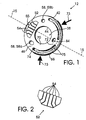
- Figure 1 is top perspective view of an embodiment of the memory module. The struts are shown unflexed with solid lines and flexed with dashed lines.
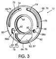
- Figure 2 is a top perspective view of the memory unit of the memory module of Figure 1.
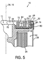
- Figure 3 is a bottom perspective view of the memory module of Figure 1.
- Figure 4 is a perspective of an embodiment of the film cassette, including the memory module of Figure 1. The location of the access site is indicated diagrammatically by a dashed line.
- Figure 5 is a partial cross-sectional view of the film cassette of Figure 4 taken substantially along line A-A of Figure 4.
- Figure 6 is a perspective view of a photographic apparatus including the film cassette of Figure 4. A controller (shown in dashed lines) and signal paths are illustrated diagrammatically.
- Figure 7 is a perspective view of the film cassette and terminal block of Figure 6.
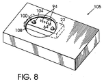
- Figure 8 is a perspective view of the module reader. The position of parts of the terminal block within the body of the reader is indicated by dashed lines.
- Figure 9 is a partially cut-away perspective view of the reader of Figure 8. The memory module of Figure 1 is loaded in the module socket of the reader.
- Figure 10 is a partial cross-sectional view of the reader and module of Figure 9. The controller of the reader and signal paths are illustrated diagrammatically.
- Figure 11 is a perspective view of another embodiment of the memory module.
-
- Referring initially to Figures 1-7 and 11, a
film cassette 10 has amemory module 12 that floats within a slot 11 formed by theshell 14 of thecassette 10. Thememory module 12 has alocator 16 and defines amodule axis 15. - A
photographic apparatus 18 receives thefilm cassette 10 in acassette station 20. Thecassette station 20 includes aterminal block 22 that has acam unit 24. When thefilm cassette 10 is loaded in thecassette station 20, thelocator 16 andcam unit 24 are in engagement, and thememory module 12 is held in place relative to thephotographic apparatus 18 and thecassette shell 14. - Referring now primarily to Figures 4-5, a
filmstrip 26 is coiled within theshell 14. Thefilm cassette 10 is illustrated as being a slightly modified Type 135 film cassette. Thefilm cassette 10 is not limited to any particular configuration. For example, thefilm cassette 10 can be a two chambered cassette, similar to a Type 110 film cassette. - The
shell 14 has aside wall 28, to whichend caps end cap 30. It is not critical which end of thecassette 10 includes slottedend cap 30, but in practice the selected end would be standardized. Alternatively, both ends of thecassette 10 can include aslotted end cap 30. Thefilm cassette 10 light-tightly holds thefilmstrip 26 in afilm space 32, coiled about acassette spool 34. Thecassette spool 34 and thecoiled filmstrip 26 each define a cassette axis 36 about which thespool 34 is free to rotate. - The module slot 11 is separate from and external to the
film space 32 and not light-tight. Theshell 14 is preferably open over theend cap 30, but can have an end wall (not illustrated) over the slot 11, if the end wall does not binder access to themodule 12 for memory usage and for removal. - Referring now primarily to Figures 1-3 and 11, the
memory module 12 has roughly the shape of a disk or lozenge with a hollowcentral passage 38 centered onmodule axis 15. Thememory module 12 has outer andinner edges lower surfaces memory module 12 is generally described herein in terms of a disk-shape like that of a flat washer. It will be understood that like considerations apply to modules of other shapes, such as the module illustrated in Figure 11. - The
memory module 12 has asupport 50 and amemory unit 52 mounted on thesupport 50. Thememory unit 52 has one or more electronic components (not separately illustrated), which are directly mounted to one or both surfaces of thesupport 50 or are mounted to a miniature circuit board (not separately illustrated, which is itself mounted to thesupport 50. Thememory unit 52 includes an array ofelectrical contacts 54 that face outward from theupper surface 46. In the embodiment shown in the figures, thememory unit 52 is an integrated circuit element, which is mounted to awindow 55 in thesupport 50 such that theelectrical contacts 54 are exposed on theupper surface 46 of themodule 12. At theupper surface 46, thecontacts 54 are generally coplanar with thesupport 50. The integrated circuit element is embedded in plastic potting or the like which provides a smooth pad 57 to ensure that thelower surface 48 does not bind against theend cap 30. - The
locator 16 of thememory module 12 includes one or more locating surfaces 58. In thememory modules 12 shown in the figures, thelocator 16 has a pair ofopposed subunits 59. Eachsubunit 59 has anopening 60. The margins of theopenings 60 form the locating surfaces 58. One of the locatingsurfaces 58a is oval in shape; the other locatingsurface 58b is circular. - Referring now primarily to Figures 1-5 and 11, the
memory module 12 is loosely-retained in the module slot 11 by theend cap 30. Thememory module 12 is repeatedly removable and replaceable in ashell 14 or series of shells without damage to thememory module 12 and, preferably, without damage to the shell orshells 14. - The
memory module 12 is held within the module slot 11 by interference features of theshell 14 andmemory module 12. The interference features allow relatively free motion of themodule 12 in a plane (indicated by dashed arrows x-y in Figure 4) perpendicular to the cassette axis 36. Thememory module 12 can pivot and translation in a plane perpendicular to the cassette axis 36 within the bounds of the slot 11. Axial movement of themodule 12 and rotational movement out of that plane is closely limited. (Terms used herein that refer to an axis, such as "axial" and "radial" do not recite a specific axis where the context indicates the relevant axis or where the indicated directions coincide. For example, themodule axis 15 and cassette axis 36 are parallel or coincident when themodule 12 is loaded in the module slot 11.) - In preferred embodiments, the
end cap 30 of theshell 14 has acollar 64 that protrudes radially inward from theside wall 28 and thememory module 12 has aretainer 66 that protrudes radially outward at theouter edge 42 of themodule 12. Thecollar 64 is positioned so as to limit the axial dimension of the module slot 11 to no more clearance than is necessary to allow thememory module 12 to move within the slot 11. Thecollar 64 andretainer 66 can each be continuous or segmented, with adjoining segments separated by 180 degrees or less. Thecollar 64 borders and defines anentry 68 for the admission of thememory module 12 into the slot 11. Thememory module 12 andshell 14 can both be rigid. In this case, the interference fit can be provided, by an axial overlap of parts achieved by insertion and rotation of thememory module 12 relative to theshell 14. Thememory module 12 andshell 14 can, alternatively provide a snap fit, in which themodule 12,shell 14, or both flex to allow installation and removal of themodule 12. It is currently preferred that theshell 14 is rigid and thesupport 50 of themodule 12 flexible, for reasons of ease of manufacture and use and to better protect theenclosed filmstrip 26. When flexed, one or more parts of thesupport 50 deflect toward themodule axis 15, reducing a radial cross-section of themodule 12. Theentry 68 of the module slot 11 has a radial cross-section that is greater than the radial cross-section of the flexedmemory module 12 and is less than the radial cross-section of thememory module 12 when thememory module 12 is not flexed. - In the embodiment shown in the figures, the
support 50 is made of a slightly flexible sheet material and has acentral hub portion 70 and a slightly thickerouter portion 72. Theouter portion 72 has a pair of cut-outs 74 which locally increase flexibility. The cut-outs 74 reduce part of theouter portion 72 to a pair ofnarrow struts 75 that border and are radially exterior to the cut-outs 74. Themodule 12 is flexed by applying a radial force or forces (indicated by arrows 73) against themodule 12 at thestruts 75. When themodule 12 is flexed, thenarrow struts 75 bend (as shown in Figure 1) reducing the radial cross-section of themodule 12. The cut-outs 74 allow the thickness of the remainder of thesupport 50 to be relatively thicker so as to better hold thememory unit 52, without an overall loss of needed flexibility. - The
retainer 66 of thesupport 50 has three equally separated segments 76 (best shown in Figure 3) that protrude from theouter edge 42 of thesupport 50. Referring particularly to Figure 5, each segment 76 has an axial dimension that is less than the axial dimension of anupper section 77 of theouter edge 42. Thecollar 64 is continuous around theend cap 30 and has the form of an inwardly directed brim. Below thecollar 64, theend cap 30 extends radially outward and forms acircular trough 78 that abuts the inside of thewall 28 of theshell 14. Theend cap 30 then turns back inward, that is, from an axial direction to a radial direction, toward thespool 34 forming aradial wall 80. Theend cap 30 recurves beyond thecollar 64 and extends axially along the outside of theside wall 28. When themodule 12 is in the slot 11, theupper section 77 is axially aligned with and radially inward from thecollar 64 and theretainer 66 is radially aligned with and axially inward from thecollar 64. The area of contact between thecollar 64 and the upper section and between the trough and theretainer 66, can be varied. It is preferred that thecollar 64 and trough have closely the same axial dimensions as the upper section andretainer 66, respectively. It is also preferred that thecollar 64 and trough have radial dimensions that are closely similar to the radial dimensions of the upper section andretainer 66, respectively. - The rotational movement or rotational and translational movement of the
memory module 12 in the radial plane, within the slot, is preferably limited bybumpers support 50 of thememory module 12 and theend cap 30 of theshell 14, respectively. Thebumpers bumpers bumper module axis 15. Thebumpers module 12 against rotation within the module slot 11; that is, thebumpers memory module 12 to rotate freely over a limited range within the module slot 11, but interfere with each other so as to block rotation beyond that limited range. In the embodiment shown in the figures, onebumper 82 is a peak or post that protrudes axially outward from theouter portion 72 of theend cap 30 into the module slot 11 and theother bumper 84 is the inner edge of a circular hole in thesupport 50. The peak and hole can alternatively be provided on thememory module 12 andend cap 30, respectively. Thebumpers memory module 12 can be shaped like a disk truncated at a chord that acts as abumper 84. Thebumper 82 of theend cap 30 is a section ofwall 28 corresponding to the chord. The bumpers shown in Figures 1-10 are preferred for use with a shaped metal end cap, sincebumper 82 can be easily shaped at the same time as the rest of theend cap 30. More complexly shaped bumpers, requiring additional shaping steps are not preferred. - The
bumpers memory module 12 in the radial plane such that the locating surfaces 58 of thelocator 16 remain, at all times, in at least partial axial alignment with a predetermined access site 61 defined by theshell 14 of the cassette. Looking at Figure 4, theshell 14 has afilm exit 88 that has a predetermined, fixed spatial relationship to the access site (indicated diagrammatically in Figure 4 by a dashed line). This ensures that the cam unit 24 (discussed in detail below) encounters the locating surfaces 58 when thecam unit 24 meets thelocator 16. - Referring now primarily to Figures 6-7, the
apparatus 18 has thecassette 10, including thememory module 12, and aphotographic device 90. The illustratedphotographic device 90 is a camera, but thephotographic device 90 is not limited to cameras. For example, thefilmstrip 26 in thecassette 10 can be processed film and thephotographic device 90 can be a digital scanner or display device. Thedevice 90 has abody 92 that includes thecassette station 20 andterminal block 22. Thecassette station 20 is configured to receive thefilm cassette 10 in a predetermined, fixed orientation. A film transport 93 (illustrated in Figure 6 by sprocket teeth) is positioned in thebody 92 so as to move thefilmstrip 26 into or both into and out of theshell 14. Thefilm cassette 10 has a fixed rotational position within thestation 20 within narrow tolerances. Thefilm cassette 10 is preferably axially loaded in thestation 20. - The
terminal block 22 is mounted in thebody 92 at an end of thestation 20. Theterminal block 22 has an array ofleads 94, thecam unit 24, and asupport structure 96. In the embodiment shown in the figures, theleads 94 are parallel spaced apart pins that are urged by individual springs 98 (illustrated diagrammatically in Figure 6) in the direction indicated by arrow "Z". The leads 94 are conductive and are spaced to electrically contactindividual contacts 54 of thememory module 12. - The
cam unit 24 has a pair ofopposed cams 100 that are aligned with theleads 94. Thecams 100 are individually spring biased in the direction "Z" bysprings 102. Thecams 100 are preferably non-conductive. Thecams 100 each have aconical cam surface 104. In the embodiment shown in the figures, the cam surfaces 104 each have the shape of a regular circular cone. - When loaded, the axis 36 of the
film cassette 10 is coextensive with anaxis 106 of thestation 20. The access site is predetermined and standardized for thecassette 10. Thus, when thecassette 10 is loaded in thestation 20, a corresponding access site in thestation 20 is also defined. Theterminal block 22 is mounted in thebody 88 in thecassette station 20 in alignment with the access site. The springs 98,102 bias theleads 94 andcam unit 24 toward engagement with thememory module 12. - In use, the
film cassette 10 is loaded into thecassette station 20 and assumes the predetermined cassette orientation. Thelocator 16 andcam unit 24 are moved relative to each other until the locating surfaces 58 and cam surfaces 104 touch. Further relative movement causes thememory module 12 to pivot within the module slot 11 until thecams 100 are centered as to the respective locating surfaces 58. The acceptable range of motion of themodule 12 within the slot 11 is determined by the capability of thecam unit 24 to orient the module during engagement of the locating surfaces 58 andcam unit 24 such that each of theleads 94 is biased against a correspondingcontact 54 and none of theleads 94 bridge twocontacts 54. - When fully seated by the biasing of the springs 98,102, the
terminal block 22 is registered with thememory module 12 and theleads 94 andcontacts 54 are held together, in alignment. Further rotation of thememory module 12 is arrested, until thefilm cassette 10 is removed from thedevice 18. In the embodiments shown in the figures, the cam surfaces 104 are conical and the locating surfaces 58 are the margins of openings. Other shapes can be provided for these surfaces as long as the combination of cam surfaces 104 and locatingsurfaces 58 would result in the described reorientation of thememory module 12 in the module slot 11. - Referring now to Figures 8-10, a
memory module reader 105 allows use of thememory module 12 when detached from acassette 10. Thereader 105 has abody 106 that has amodule socket 108 having a circumferential wall 110. Themodule socket 108 defines acylindrical socket site 112 and asocket axis 114. Aterminal block 22 having the same features as theterminal block 22 previously described, is joined to thebody 106. Thecam unit 24 of theterminal block 22 is aligned with thesocket site 112. The springs 98,102 bias thecam unit 24 and leads 94, respectively, toward thesocket site 112. Thereader 105 can have abumper 82 complementary to amemory module bumper 84, as previously described for thecassette shell 14; but such a reader bumper is optional, since rotation of thememory module 12 within thereader 105 after alignment, is deterred by thecam unit 24 of theterminal block 22. - The
module socket 108 has acollar 64 that extends radially inward from the circumferential wall 110 in the same manner as thecollar 64 previously described. Thecollar 64 borders and defines an opening for the admission of thememory module 12 into thesocket site 112. Below thecollar 64, thesocket 108 is sized to receive theretainer 66 and permit rotation of themodule 12. - When the
memory module 12 is loaded into thesocket 108 thememory module 12 is flexed, inserted past thecollar 64, and then released. Theunflexed memory module 12 fits loosely within the circumferential wall 110 of themodule socket 108. The leads 94 andcams 100 impinge against theupper surface 46 of thememory module 12 and bias thememory module 12 against thecollar 64. (In Figure 9, theupper surface 46 faces the bottom of the drawing.) The biasing by the springs 98,102 is easily overcome, allowing manual or automatic rotation of thememory module 12 within thesocket site 112. Rotation is needed to bring thelocator 16 andcam unit 24 into alignment, unless thememory module 12 was initially loaded in an aligned position. Once thememory module 12 andterminal block 22 are aligned within thesocket site 112, thecams 100 engage the locating surfaces 58, and theleads 94 engage correspondingcontacts 54 of thememory module 12. Further rotation of thememory module 12 is deterred by the engagement of thelocator 16 andcam unit 24. - In both the
apparatus 18 andreader 105, theleads 94 are operatively connected bysignal paths 116 to acontroller 118 which allows the memory of thememory module 12 to be accessed for reading or writing or both. Suitable hardware and controllers are well known to those of skill in the art For example, the leads can be hard wired to a programmable computer or can be connected by wireless interface or can be remotely connected through a network. - The
memory module 12 can be used to store a variety of information. For example, thememory module 12 can store photofinishing information or user recorded information about individual exposures. Thememory module 12 can be installed onfilm cassette 10 at the time of manufacture or by a film dealer at the time of purchase or by an end-user. Thememory module 12 can be retained on thefilm cassette 10 when the cassette is submitted for photofinishing. The information in memory can be read out by the photofinisher with thememory module 12 retained on thecassette shell 14 or thememory module 12 can be removed from theshell 14 prior to reading. Thememory module 12 can be used once by a purchaser and can then be recycled or disposed of after photofinishing. Thememory module 12 can alternatively, be returned to the purchaser with processed film. Since with Type 135 film the cassette is not returned, thememory module 12 is separated from the cassette during photofinishing. The returnedmemory module 12 can be kept by the user to retain information recorded by the user or relating to photofinishing. Thememory module 12 can alternatively, be installed by the user on a new film unit. For reuse, necessary memory must be cleared at photofinishing or later by the user. Thereader 105 can be used to add, remove, or modify information recorded in thememory module 12 at any time thememory module 12 is detached from a cartridge. For example, thereader 105 can be used to write information to thememory module 12 prior to assembly of thememory module 12 into a cartridge and can be used by a user to read out information, such as sounds or lighting conditions, recorded at the time of image capture.
Claims (10)
- A memory module reader for use with a memory module, said reader comprising:a body having a module socket, said module socket defining a cylindrical contact site and a site axis;a terminal block joined to said body, said terminal block including a plurality of leads and a cam unit having at least one cam surface, said cam unit being aligned with said contact site, said cam unit being biased toward said contact site.
- The reader of claim 1 wherein said cam unit includes a pair of spaced apart cams, each said cam having a cam surface.
- The reader of claim 1 or 2 wherein said leads are resiliently biased toward said contact site independent of said cams.
- The reader of claim 1, 2, or 3 wherein said module socket has a circumferential wall and a collar extending radially inward from said circumferential wall.
- An assembly comprising:a memory module reader including:a body having a module socket, said module socket defining a cylindrical contact site and a site axis;a terminal block joined to said body, said terminal block including a plurality of leads and a cam unit having at least one cam surface, said cam unit being aligned with said contact site, said cam unit being biased toward said contact site; anda memory module removably retained in said module socket, said memory module including:a flexible support; anda memory element fixed to said support.
- The assembly of claim 5 wherein said support is discoid.
- The assembly of claim 5 or 6 wherein said memory module has a locator and a plurality of contacts aligned with said locator.
- The assembly of claim 7 wherein said locator has a pair of opposed subunits, each said subunit having a locating surface, one of said locating surfaces having an oval shape and the other of said surfaces having a circular shape.
- The assembly of claim 5, 6, 7, or 8 wherein said cam unit includes a pair of spaced apart cams, each said cam having a cam surface, said cams being resiliently biased toward said contact site.
- The assembly of claim 5, 6, 7, 8, or 9 wherein said memory module is arrested and rotationally oriented relative to said axis by said cam unit, said cam unit includes a pair of spaced apart cams, each said cam having a cam surface, and said locator has a pair of opposed subunits, each said subunit having a locating surface.
Applications Claiming Priority (2)
| Application Number | Priority Date | Filing Date | Title |
|---|---|---|---|
| US285159 | 1988-12-16 | ||
| US09/285,159 US6104883A (en) | 1999-04-01 | 1999-04-01 | Memory module reader |
Publications (1)
| Publication Number | Publication Date |
|---|---|
| EP1041429A1 true EP1041429A1 (en) | 2000-10-04 |
Family
ID=23093008
Family Applications (1)
| Application Number | Title | Priority Date | Filing Date |
|---|---|---|---|
| EP00201013A Withdrawn EP1041429A1 (en) | 1999-04-01 | 2000-03-20 | Memory module reader for memory modules used with film cassettes |
Country Status (3)
| Country | Link |
|---|---|
| US (1) | US6104883A (en) |
| EP (1) | EP1041429A1 (en) |
| JP (1) | JP2000315380A (en) |
Cited By (1)
| Publication number | Priority date | Publication date | Assignee | Title |
|---|---|---|---|---|
| EP4043956A1 (en) * | 2021-02-16 | 2022-08-17 | Canon Kabushiki Kaisha | Electronic apparatus capable of communicating with external device mounted thereon, and external device |
Citations (6)
| Publication number | Priority date | Publication date | Assignee | Title |
|---|---|---|---|---|
| US4306795A (en) * | 1980-03-10 | 1981-12-22 | U.S. Philips Corporation | Safety-latching mechanism for a camera magazine, and camera and magazine provided with such a mechanism |
| US4509258A (en) * | 1982-07-08 | 1985-04-09 | Amp Incorporated | Connector centering device and method for using |
| DE3812667A1 (en) * | 1988-04-15 | 1989-10-26 | Siemens Ag | LIGHT HOUSING FOR STREET LIGHTS |
| US4932889A (en) * | 1988-03-25 | 1990-06-12 | Amphenol Corporation | Chipcard reader |
| DE4310517A1 (en) * | 1993-03-31 | 1994-10-06 | Wolfgang Neifer | Device for reading chip (smart) cards |
| EP1014167A2 (en) * | 1998-12-23 | 2000-06-28 | Eastman Kodak Company | Film cartridge with a memory module and camera for recording information in said module |
Family Cites Families (8)
| Publication number | Priority date | Publication date | Assignee | Title |
|---|---|---|---|---|
| JPS57202524A (en) * | 1981-06-08 | 1982-12-11 | Minolta Camera Co Ltd | Equipment for automatically setting sensitivity of film |
| JPS60103332A (en) * | 1983-11-11 | 1985-06-07 | Canon Inc | Information input device of camera |
| US4693574A (en) * | 1984-07-27 | 1987-09-15 | Canon Kabushiki Kaisha | Film information reading device |
| JPH01289948A (en) * | 1988-05-17 | 1989-11-21 | Minolta Camera Co Ltd | Film container |
| US5526084A (en) * | 1991-09-12 | 1996-06-11 | Fuji Photo Film Co., Ltd. | Photographic film cassette which is easily removed from a camera and camera for use with the same |
| US5349401A (en) * | 1993-06-04 | 1994-09-20 | Eastman Kodak Company | Orientation independent, detachable film cartridge, memory module |
| US5394206A (en) * | 1993-06-04 | 1995-02-28 | Eastman Kodak Company | Orientation independent, detachable film cartridge, memory module |
| JP3371405B2 (en) * | 1994-04-15 | 2003-01-27 | 富士写真フイルム株式会社 | Film cartridge and film image input device |
-
1999
- 1999-04-01 US US09/285,159 patent/US6104883A/en not_active Expired - Lifetime
-
2000
- 2000-03-20 EP EP00201013A patent/EP1041429A1/en not_active Withdrawn
- 2000-03-23 JP JP2000082330A patent/JP2000315380A/en active Pending
Patent Citations (6)
| Publication number | Priority date | Publication date | Assignee | Title |
|---|---|---|---|---|
| US4306795A (en) * | 1980-03-10 | 1981-12-22 | U.S. Philips Corporation | Safety-latching mechanism for a camera magazine, and camera and magazine provided with such a mechanism |
| US4509258A (en) * | 1982-07-08 | 1985-04-09 | Amp Incorporated | Connector centering device and method for using |
| US4932889A (en) * | 1988-03-25 | 1990-06-12 | Amphenol Corporation | Chipcard reader |
| DE3812667A1 (en) * | 1988-04-15 | 1989-10-26 | Siemens Ag | LIGHT HOUSING FOR STREET LIGHTS |
| DE4310517A1 (en) * | 1993-03-31 | 1994-10-06 | Wolfgang Neifer | Device for reading chip (smart) cards |
| EP1014167A2 (en) * | 1998-12-23 | 2000-06-28 | Eastman Kodak Company | Film cartridge with a memory module and camera for recording information in said module |
Cited By (3)
| Publication number | Priority date | Publication date | Assignee | Title |
|---|---|---|---|---|
| EP4043956A1 (en) * | 2021-02-16 | 2022-08-17 | Canon Kabushiki Kaisha | Electronic apparatus capable of communicating with external device mounted thereon, and external device |
| CN114945065A (en) * | 2021-02-16 | 2022-08-26 | 佳能株式会社 | Electronic apparatus and external device capable of communicating with external device mounted thereon |
| US11805307B2 (en) | 2021-02-16 | 2023-10-31 | Canon Kabushiki Kaisha | Electronic apparatus capable of wirelessly communicating with external device mounted thereon, and external device |
Also Published As
| Publication number | Publication date |
|---|---|
| JP2000315380A (en) | 2000-11-14 |
| US6104883A (en) | 2000-08-15 |
Similar Documents
| Publication | Publication Date | Title |
|---|---|---|
| US4194822A (en) | Photographic film cartridge assembly and camera | |
| JP4141910B2 (en) | Single reel tape cartridge and method for providing a memory element | |
| EP0423691A2 (en) | Camera | |
| US5870642A (en) | Panoramic support for camera permits horizontal-format and vertical-format image recordings | |
| US20020012535A1 (en) | Film unit having radio-frequency identification transponder | |
| US6157784A (en) | Film cassette having loosely-retained, reversibly separable memory module, and photographic apparatus | |
| US6104883A (en) | Memory module reader | |
| JPH0339768Y2 (en) | ||
| JPH0713302A (en) | Memory module for attachable and detachable film cartridge | |
| US6731869B2 (en) | Electrical connecting structure in lens barrels of cameras | |
| EP1014167A2 (en) | Film cartridge with a memory module and camera for recording information in said module | |
| JP2001051177A (en) | Photographing lens holding method | |
| US6393224B1 (en) | E-film cartridge with sensor avoidance feature | |
| US5659826A (en) | Lens-fitted photographic film unit with picture frame size changing device | |
| US5447828A (en) | Photographic film | |
| JP2823949B2 (en) | Photo film patrone | |
| KR0133723Y1 (en) | Photographic elements moving device of a camera | |
| JPS6159976A (en) | Electronic camera | |
| CN220543186U (en) | Lens, lens mounting module and image acquisition equipment thereof | |
| CA2054884A1 (en) | Image bearing template for instant film assemblages | |
| KR100488320B1 (en) | Photo film unit with lens | |
| US6287022B1 (en) | Indicated state changing pin and method of bending indicating pieces | |
| JPH036896Y2 (en) | ||
| JPH0421852B2 (en) | ||
| JPH06186465A (en) | Code plate structure for lens barrel |
Legal Events
| Date | Code | Title | Description |
|---|---|---|---|
| PUAI | Public reference made under article 153(3) epc to a published international application that has entered the european phase |
Free format text: ORIGINAL CODE: 0009012 |
|
| AK | Designated contracting states |
Kind code of ref document: A1 Designated state(s): AT BE CH CY DE DK ES FI FR GB GR IE IT LI LU MC NL PT SE |
|
| AX | Request for extension of the european patent |
Free format text: AL;LT;LV;MK;RO;SI |
|
| AKX | Designation fees paid | ||
| REG | Reference to a national code |
Ref country code: DE Ref legal event code: 8566 |
|
| STAA | Information on the status of an ep patent application or granted ep patent |
Free format text: STATUS: THE APPLICATION IS DEEMED TO BE WITHDRAWN |
|
| 18D | Application deemed to be withdrawn |
Effective date: 20010405 |