EP1041424A2 - Integrated optical Mach Zehnder structures - Google Patents
Integrated optical Mach Zehnder structures Download PDFInfo
- Publication number
- EP1041424A2 EP1041424A2 EP00301124A EP00301124A EP1041424A2 EP 1041424 A2 EP1041424 A2 EP 1041424A2 EP 00301124 A EP00301124 A EP 00301124A EP 00301124 A EP00301124 A EP 00301124A EP 1041424 A2 EP1041424 A2 EP 1041424A2
- Authority
- EP
- European Patent Office
- Prior art keywords
- mach zehnder
- optical
- mach
- central
- zehnder
- Prior art date
- Legal status (The legal status is an assumption and is not a legal conclusion. Google has not performed a legal analysis and makes no representation as to the accuracy of the status listed.)
- Withdrawn
Links
- 230000003287 optical effect Effects 0.000 title claims abstract description 100
- 230000008878 coupling Effects 0.000 claims description 44
- 238000010168 coupling process Methods 0.000 claims description 44
- 238000005859 coupling reaction Methods 0.000 claims description 44
- 230000001419 dependent effect Effects 0.000 claims description 12
- 230000000694 effects Effects 0.000 claims description 11
- 238000000034 method Methods 0.000 claims description 6
- 230000035945 sensitivity Effects 0.000 claims description 4
- 230000003595 spectral effect Effects 0.000 claims description 2
- 238000010521 absorption reaction Methods 0.000 claims 1
- 238000012886 linear function Methods 0.000 claims 1
- 238000005253 cladding Methods 0.000 description 13
- 239000011521 glass Substances 0.000 description 13
- VYPSYNLAJGMNEJ-UHFFFAOYSA-N Silicium dioxide Chemical compound O=[Si]=O VYPSYNLAJGMNEJ-UHFFFAOYSA-N 0.000 description 12
- 238000010561 standard procedure Methods 0.000 description 10
- 239000000463 material Substances 0.000 description 9
- 239000000758 substrate Substances 0.000 description 9
- 238000010438 heat treatment Methods 0.000 description 8
- XUIMIQQOPSSXEZ-UHFFFAOYSA-N Silicon Chemical compound [Si] XUIMIQQOPSSXEZ-UHFFFAOYSA-N 0.000 description 6
- 229910052710 silicon Inorganic materials 0.000 description 6
- 239000010703 silicon Substances 0.000 description 6
- 239000000377 silicon dioxide Substances 0.000 description 6
- 238000010586 diagram Methods 0.000 description 4
- 239000000470 constituent Substances 0.000 description 3
- 238000004458 analytical method Methods 0.000 description 2
- 238000010276 construction Methods 0.000 description 2
- 238000005516 engineering process Methods 0.000 description 2
- 238000005530 etching Methods 0.000 description 2
- 230000010363 phase shift Effects 0.000 description 2
- VYZAMTAEIAYCRO-UHFFFAOYSA-N Chromium Chemical compound [Cr] VYZAMTAEIAYCRO-UHFFFAOYSA-N 0.000 description 1
- 230000033228 biological regulation Effects 0.000 description 1
- 229910052804 chromium Inorganic materials 0.000 description 1
- 239000011651 chromium Substances 0.000 description 1
- 230000008021 deposition Effects 0.000 description 1
- 239000000835 fiber Substances 0.000 description 1
- 230000009477 glass transition Effects 0.000 description 1
- PCHJSUWPFVWCPO-UHFFFAOYSA-N gold Chemical compound [Au] PCHJSUWPFVWCPO-UHFFFAOYSA-N 0.000 description 1
- 239000010931 gold Substances 0.000 description 1
- 229910052737 gold Inorganic materials 0.000 description 1
- 238000004519 manufacturing process Methods 0.000 description 1
- 229910052751 metal Inorganic materials 0.000 description 1
- 239000002184 metal Substances 0.000 description 1
- 229910021421 monocrystalline silicon Inorganic materials 0.000 description 1
- 230000007935 neutral effect Effects 0.000 description 1
- 230000001902 propagating effect Effects 0.000 description 1
- 230000001629 suppression Effects 0.000 description 1
- 239000010409 thin film Substances 0.000 description 1
Images


Classifications
-
- G—PHYSICS
- G02—OPTICS
- G02F—OPTICAL DEVICES OR ARRANGEMENTS FOR THE CONTROL OF LIGHT BY MODIFICATION OF THE OPTICAL PROPERTIES OF THE MEDIA OF THE ELEMENTS INVOLVED THEREIN; NON-LINEAR OPTICS; FREQUENCY-CHANGING OF LIGHT; OPTICAL LOGIC ELEMENTS; OPTICAL ANALOGUE/DIGITAL CONVERTERS
- G02F1/00—Devices or arrangements for the control of the intensity, colour, phase, polarisation or direction of light arriving from an independent light source, e.g. switching, gating or modulating; Non-linear optics
- G02F1/01—Devices or arrangements for the control of the intensity, colour, phase, polarisation or direction of light arriving from an independent light source, e.g. switching, gating or modulating; Non-linear optics for the control of the intensity, phase, polarisation or colour
- G02F1/21—Devices or arrangements for the control of the intensity, colour, phase, polarisation or direction of light arriving from an independent light source, e.g. switching, gating or modulating; Non-linear optics for the control of the intensity, phase, polarisation or colour by interference
- G02F1/225—Devices or arrangements for the control of the intensity, colour, phase, polarisation or direction of light arriving from an independent light source, e.g. switching, gating or modulating; Non-linear optics for the control of the intensity, phase, polarisation or colour by interference in an optical waveguide structure
-
- G—PHYSICS
- G02—OPTICS
- G02F—OPTICAL DEVICES OR ARRANGEMENTS FOR THE CONTROL OF LIGHT BY MODIFICATION OF THE OPTICAL PROPERTIES OF THE MEDIA OF THE ELEMENTS INVOLVED THEREIN; NON-LINEAR OPTICS; FREQUENCY-CHANGING OF LIGHT; OPTICAL LOGIC ELEMENTS; OPTICAL ANALOGUE/DIGITAL CONVERTERS
- G02F1/00—Devices or arrangements for the control of the intensity, colour, phase, polarisation or direction of light arriving from an independent light source, e.g. switching, gating or modulating; Non-linear optics
- G02F1/29—Devices or arrangements for the control of the intensity, colour, phase, polarisation or direction of light arriving from an independent light source, e.g. switching, gating or modulating; Non-linear optics for the control of the position or the direction of light beams, i.e. deflection
- G02F1/31—Digital deflection, i.e. optical switching
- G02F1/313—Digital deflection, i.e. optical switching in an optical waveguide structure
- G02F1/3136—Digital deflection, i.e. optical switching in an optical waveguide structure of interferometric switch type
-
- G—PHYSICS
- G02—OPTICS
- G02F—OPTICAL DEVICES OR ARRANGEMENTS FOR THE CONTROL OF LIGHT BY MODIFICATION OF THE OPTICAL PROPERTIES OF THE MEDIA OF THE ELEMENTS INVOLVED THEREIN; NON-LINEAR OPTICS; FREQUENCY-CHANGING OF LIGHT; OPTICAL LOGIC ELEMENTS; OPTICAL ANALOGUE/DIGITAL CONVERTERS
- G02F1/00—Devices or arrangements for the control of the intensity, colour, phase, polarisation or direction of light arriving from an independent light source, e.g. switching, gating or modulating; Non-linear optics
- G02F1/01—Devices or arrangements for the control of the intensity, colour, phase, polarisation or direction of light arriving from an independent light source, e.g. switching, gating or modulating; Non-linear optics for the control of the intensity, phase, polarisation or colour
- G02F1/0147—Devices or arrangements for the control of the intensity, colour, phase, polarisation or direction of light arriving from an independent light source, e.g. switching, gating or modulating; Non-linear optics for the control of the intensity, phase, polarisation or colour based on thermo-optic effects
-
- G—PHYSICS
- G02—OPTICS
- G02F—OPTICAL DEVICES OR ARRANGEMENTS FOR THE CONTROL OF LIGHT BY MODIFICATION OF THE OPTICAL PROPERTIES OF THE MEDIA OF THE ELEMENTS INVOLVED THEREIN; NON-LINEAR OPTICS; FREQUENCY-CHANGING OF LIGHT; OPTICAL LOGIC ELEMENTS; OPTICAL ANALOGUE/DIGITAL CONVERTERS
- G02F1/00—Devices or arrangements for the control of the intensity, colour, phase, polarisation or direction of light arriving from an independent light source, e.g. switching, gating or modulating; Non-linear optics
- G02F1/01—Devices or arrangements for the control of the intensity, colour, phase, polarisation or direction of light arriving from an independent light source, e.g. switching, gating or modulating; Non-linear optics for the control of the intensity, phase, polarisation or colour
- G02F1/015—Devices or arrangements for the control of the intensity, colour, phase, polarisation or direction of light arriving from an independent light source, e.g. switching, gating or modulating; Non-linear optics for the control of the intensity, phase, polarisation or colour based on semiconductor elements having potential barriers, e.g. having a PN or PIN junction
- G02F1/025—Devices or arrangements for the control of the intensity, colour, phase, polarisation or direction of light arriving from an independent light source, e.g. switching, gating or modulating; Non-linear optics for the control of the intensity, phase, polarisation or colour based on semiconductor elements having potential barriers, e.g. having a PN or PIN junction in an optical waveguide structure
Definitions
- This invention relates to integrated optical Mach Zehnder structures, and in particular to such structures constructed in integrated optical waveguide format.
- a format typically, but not necessarily, comprises a silicon substrate upon which has been grown, in succession, a dielectric layer of buffer material, a waveguide layer of higher refractive index material, and a cladding layer which is not deposited until after the waveguide layer has been patterned and selectively etched to produce a pattern of ribs (cores) of waveguide layer material.
- the invention is particularly concerned with the regulation of birefringence in integrated optical waveguide format dynamically controllable Mach Zehnders, and is also concerned with the use of such Mach Zehnders as wavelength selective controllable attenuators.
- Birefringence is significant in such Mach Zehnders because such birefringence has the effect of making the optical attenuation exhibited by such a structure different for the two principal states of polarisation (principal SOPs).
- the integrated optical waveguides that were initially produced using silica on single crystal silicon technology exhibited significant birefringence which has been attributed to the effects of anisotropic strain resulting from thermal expansion coefficient mismatch between that of the material of the waveguide cores and that of the underlying silicon substrate. More recently, it has been possible to produce integrated optical waveguides with much reduced birefringence.
- One method for producing such low birefringence integrated optical waveguides involves choosing for the material of the cladding layer a material having a thermal expansion coefficient matched with that of the material of the substrate, as is described in the specifications of United States Patent Application No. 08/942189, and its European counterpart, European Patent Application No. 98306084.9.
- thermo-optic phase-shifters to adjust the relative optical path length of the two interference arms of an integrated optical waveguide Mach Zehnder is known and is, for instance, described in the invited paper by Masao Kawachi entitled, 'Silica waveguides on silicon and their applications to integrated-optic components', Optical and Quantum Electronics, Vol. 22, (1990) pp391 - 416.
- phase-shifter employs a thin-film Joule-effect heating strip on the cladding layer above and in registration with a portion of underlying waveguide core.
- thermo-optic constants of the constituent parts of an integrated optical waveguide are such that, when an electric current is passed through a heating strip overlying such a waveguide, the effective refractive index of the underlying waveguide is increased. Hence the optical path length of that waveguide is increased.
- the heating also has a mechanical effect due to the thermal expansion coefficient mismatch between these constituent parts. This effect is to introduce stress birefringence because the locally heated material is more readily able to expand in the direction extending normal to the plane of the substrate than in any direction lying in the plane of that substrate.
- This stress-induced birefringence can be reduced by the etching of grooves into the integrated optics structure on either side of the heating strip in the same manner as is described in the above-mentioned paper for reducing the stress-induced birefringence in integrated optics waveguides employed in other types of integrated optics device.
- thermo-optic phase-shifter This groove etching method of reducing the value of stress-induced birefringence in a thermo-optic phase-shifter is not susceptible of adjustment after the creation of the phase-shifter. If, for a specific integrated optics Mach Zehnder structure incorporating one or more such phase-shifters, the particular dimensions of the or each phase-shifter are found in practice not to provide adequate suppression of birefringence, there is no obvious way of remedying the situation in respect of that specific structure
- the present invention is directed to the provision of an integrated optical waveguide format Mach Zehnder with increased flexibility of adjustment affording the possibility of adjustment not only of the differential optical path length of the interference arms, but also of their differential birefringence.
- thermo-optic phase-shifter in each interference arm of the Mach Zehnder, and furnishing one of these phase-shifters with a structure that provides it with a temperature coefficient of birefringence different from that of the other.
- thermo-optic phase-shifter components of such Mach Zehnders In this way not only can there be compensation for birefringence effects of thermo-optic phase-shifter components of such Mach Zehnders, but in certain circumstances compensation also for birefringence effects in other components, such as those of the splitter/combiners by which the interference arms of the Mach Zehnder are coupled with its input and output.
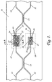
- an integrated optical waveguide structure 10 is provided with a pair of single mode optical waveguides 11 and 12 which have two regions 13 and 14 of close approach where the two waveguides are so close together that the evanescent fields of the zero order guided modes overlap significantly.
- the length of each of these regions 13 and 14 of close approach is such as to provide a desired level of coupling between the two waveguides 11 and 12 at that region, typically 3dB coupling.
- an integrated optics Mach Zehnder waveguide configuration is provided, in which the portions 15 and 16 of waveguides 11 and 12 that extend between the two couplers 13 and 14 constitute the two interference arms of the Mach Zehnder.
- thermo-optic phase-shifters 17 and 18 Into these two interference arms are inserted two thermo-optic phase-shifters 17 and 18. An understanding of the construction of the phase-shifters 17 and 18 is facilitated by reference to Figure 2 in conjunction with Figure 1, Figure 2 schematically depicting a cross-section through phase-shifter 17 on the line A A'.
- the substructure of the integrated optics waveguide structure 10 was built upon a silicon substrate 20. On this substrate was formed a silica buffer layer 21. On the buffer layer was deposited a layer of core glass, which was subsequently patterned and selectively etched to leave the waveguide cores 11 and 12 (core 12 not shown in Figure 2). These cores were covered with a layer 22 of cladding glass.
- the buffer and cladding glass layers 21 and 22 have matching refractive indices, a value that is less than that of the core glass of the waveguide cores 11 and 12.
- the relative glass transition temperatures of the buffer, core glass and cladding glass layers are chosen to keep the distortion of the cores, consequent upon deposition of the cladding glass, within acceptable bounds.
- the thermal expansion coefficient of the cladding glass is preferably matched with that of the silicon substrate.
- the waveguides 11 and 12 had a 5 ⁇ m wide by 6 ⁇ m high rectangular cross-section, and the cladding glass layer 22 provided an overcladding 12 ⁇ m thick.
- the two waveguides were separated by approximately 4 ⁇ m in the coupling regions 13 and 14 of close approach.
- the core/cladding refractive index difference was 0.011, and the minimum bend radius of the curved portions of the waveguides was 5mm.
- thermo-optic phase-shifter In order to form a thermo-optic phase-shifter, a layer of electrically resistive material, such as chromium, is deposited upon the cladding glass, is patterned and etched to leave a heating strip 23 together with areas 24a, 25a and 26a to which contact pads 24 and 25, and low resistance links 26 between the heater strip and those contact pads may be respectively bonded.
- the pads 24 and 25, and their links 26 are formed in a subsequently deposited, patterned and etched layer of contact metal, such as gold.
- phase-shifter 18 When the phase-shifter 18 is energised to raise the temperature of that portion of the core 12 underlying its heating strip 23 by a predetermined amount above its surroundings, the effect of the thermal expansion coefficient mismatch of that core glass is to subject the core to anisotropic stress because the geometry of its environment is such that the core is more constrained against lateral expansion in the plane of the cladding glass layer 22 than it is constrained against expansion in the direction normal to that layer.
- This anisotropic stress produces birefringence.
- the anisotropic stress is not so great because the core is, by virtue of the etched wells 27, less constrained against lateral expansion. Accordingly, for any given temperature rise, the induced value of birefringence per unit length is less in phase-shifter 17 than in phase-shifter 18.
- phase-shifter 17 of waveguide 11 has an effective length of d 1 over which the temperature is raised by t 1
- phase-shifter 18 of waveguide 12 has an effective length of d 2 over which the temperature is raised by t 2 .
- the corresponding optical path length increment, l 1ll (k + k') d 1 t 1 where k' is a constant that characterises the birefringence per unit length, per unit temperature rise of phase-shifter 17, and has a smaller modulus than k.
- the Mach Zehnder of figures 1 and 2 is as a dynamically controllable optical attenuator.
- the device is essentially a four-port device, and so provides attenuation of light launched into the Mach Zehnder by way of either waveguide 11 or 12 to emerge from the far end of the Mach Zehnder by way of the same waveguide (straight-through attenuation), and also of light launched into the Mach Zehnder by way of either one of waveguides 11 and 12 to emerge from the far end of the Mach Zehnder by way of the other waveguide (cross-over attenuation).
- each of the coupling regions 13 and 14 is provided by a region of close approach of the two waveguides 11 and 12, these close approach regions each thereby forming a four-port directional coupler.
- Power input on either waveguide is shared by the coupling region between the two waveguides.
- An alternative way of sharing power between the two waveguides is by the use of a Y-junction or Y-directional coupler.
- the Mach Zehnder of Figure 3 is distinguished from that of Figure 1 solely in that a pair of symmetrical Y-directional couplers 33 and 34, with associated single mode waveguides 30 and 31 have been substituted for the four-port directional couplers 13 and 14.
- Optical power that is launched into the Mach Zehnder by way of the guided mode of waveguide 30 is divided in equal proportions between the waveguides 11 and 12 by Y-directional coupler 33.
- the proportion of the power that is coherently launched into Y-directional coupler 34 from waveguides 11 and 12 that is then launched by that Y-directional coupler into the guided mode of its waveguide 31 depends upon the phase relationship between the power propagating in the two waveguides at the point of entry into the Y-directional coupler.
- the Mach Zehnder of Figures 2 and 3 can also be used as an optical attenuator.
- the Mach Zehnder has only two ports, and so provides attenuation of light launched into the Mach Zehnder by way of the guided mode of waveguide 30 to emerge from the far end by way of the guided mode of waveguide 31.
- the Mach Zehnder of Figures 1 and 2 When the Mach Zehnder of Figures 1 and 2 is used as an optical attenuator the amount of straight-through attenuation varies sinusoidally as the length of one interference arm is increased with respect to that of the other arm. In the absence of any losses within the Mach Zehnder, the theoretical minimum value of straight-through attenuation is zero, while the maximum value depends upon the strength of coupling afforded by the two couplers 13 and 14. In the absence of any losses within the Mach Zehnder, the theoretical maximum value of straight-through attenuation is infinity, and this occurs when the coupling strength is 3dB.
- the Mach Zehnders of Figures 1, 2 and 3 are stand-alone Mach Zehnders, but the invention is applicable also to more complex Mach Zehnder structures having a series combination of two or more component Mach Zehnders that are close coupled by having the second directional coupler of one component Mach Zehnder of the complex structure constitute the first directional coupler of the next component Mach Zehnder of the complex structure.
- a complex Mach Zehnder of particular interest is the triple Mach Zehnder in which the three component Mach Zehnders of the structure comprise a central Mach Zehnder sandwiched between two matched end Mach Zehnders having interference arms with matching optical path differences of a value that is in general different from that of the central Mach Zehnder.
- This triple Mach Zehnder is capable of having features incorporated into it to reduce both its polarisation-dependence and its wavelength-dependence as compared with the corresponding dependencies of the single stand-alone Mach Zehnder of Figures 1 and 2.
- the central Mach Zehnder of the triple Mach Zehnder of Figure 4 has all the components of the stand-alone Mach Zehnder of Figures 1 and 2, and these components have been assigned the same index numerals in Figure 4 as in Figure 2. To these components are added two further coupling regions 43 and 44 similar to coupling regions 13 and 14. Coupling regions 43 and 44 respectively form the outer coupling regions of the end Mach Zehnders of the triple Mach Zehnder.
- the coupling regions 13 and 14 correspondingly form the inner coupling regions of the two end Mach Zehnders while at the same time functioning as the end coupling regions of the central Mach Zehnder.
- the portions of the two waveguides 11 and 12 extending between coupling regions 13 and 43, and between coupling regions 14 and 44, constitute the interference arms of these two end Mach Zehnders, and in each instance the two interference arms differ in optical path length by an amount that corresponds at least approximately to a phase shift of ⁇ /2 for a particular wavelength of interest, ⁇ 0 , this phase shift feature being indicated respectively at 45 and 46.
- This particular wavelength of interest, ⁇ 0 is typically the centre wavelength of a spectral spread of wavelengths for which the attenuator has been designed to operate.
- the provision of the fixed amount of differential birefringence is represented by a fixed birefringence element 47, while the provision of the fixed amount of differential optical path length is represented by an incremental fixed length element 48.
- the fixed birefringence element 47 is represented in broken outline because, though its function can be provided by a discrete element, it is typically more convenient to incorporate its function into the operation of the phase shifters 17 and 18.
- the incremental fixed length element 48 is represented in full outline because, though its function can be incorporated into the operation of the phase shifters 17 and 18, it is typically more convenient to provide it as a discrete element.
- the value of attenuation provided by such a stand-alone Mach Zehnder is dependent not only upon the difference in optical path length of its two interference arms, but also upon the coupling strength presented by its component couplers. Therefore the attenuation provided by such a Mach Zehnder is generally polarisation dependent by virtue of the fact that the coupling strength of its component couplers is polarisation dependent though, under certain specific conditions, the attenuation is the same for both principal SOPs of its component couplers.
- the division of power between the two output ports of a stand-alone Mach Zehnder with a ⁇ /2 phase difference in its interference arms is less sensitive to small departures from 3dB in the coupling strength of its couplers than is a single one of its couplers existing as a stand-alone element.
- This reduction in power sharing sensitivity is, however, realised at the expense of the introduction of a sensitivity of the phase relationship between the signals in the two output ports of the stand-alone Mach Zehnder to changes in the coupling strength exhibited by its two couplers.
- the triple Mach Zehnder of Figure 4 its couplers 13, 14, 43 and 44 will exhibit a coupling strength of 3dB for light of one of their principal SOPs and a particular wavelength.
- the outputs from the input and Mach Zehnder will therefore be in phase quadrature for light of this wavelength and SOP. Accordingly, if the interference arms of the central Mach Zehnder are of identical optical path length, the inputs to the output end Mach Zehnder will also be in phase quadrature, and hence the triple Mach Zehnder will operate to provide maximum straight-through attenuation for light of this wavelength and SOP.
- phase relationship that is required for the output end Mach Zehnder to operate to maximise the straight-through attenuation presented by the triple Mach Zehnder is not ( ⁇ /2 + ⁇ ), but is ( ⁇ /2 - ⁇ ).
- the interference arms of the central Mach Zehnder of the triple Mach Zehnder should have a difference in optical path length providing a zero phase difference for one principal SOP, and a 2 ⁇ phase difference for the other SOP.
- This is provided by the birefringence of birefringence element 47.
- this birefringence could be provided by an element separate and distinct from the phase adjusters 17 and 18, it will generally be preferred to provide such birefringence as part of the birefringence provided by those phase adjusters 17 and 18.
- the condition required for the triple Mach Zehnder to retain the maximised straight-through attenuation state is the requirement that the interference arms of its central Mach Zehnder should have a difference in optical path length providing a 2 ⁇ phase difference.
- This phase difference is provided by the incremental fixed length element 48.
- the optimised value of the incremental fixed length element 48 depends upon the particular construction of the couplers 13, 14, 43 and 44, and amounts to between three and five wavelengths ⁇ 0 .
- a use for triple Mach Zehnders that is related to their use as substantially neutral density optical attenuators over a particular wavelength range of interest, is use as harmonic optical filters that are dynamically tuneable both in respect of wavelength and optical density.
- Such use is for instance described by K Inoue et al in an article entitled, 'Tunable Gain Equalization Using a Mach-Zehnder Optical Filter in Multistage Fiber Amplifiers', IEEE Photonics Technology Letters, vol. 3, no. 8, pp 718 - 720.
- a facility for phase adjustment is provided in the pair of interference arms of each of the three constituent Mach Zehnders of the triple Mach Zehnder.
- a triple Mach Zehnder with this facility, and that embodies the present invention in a preferred form, is depicted in Figure 5.
- the triple Mach Zehnder of this Figure 5 differs from its counterpart triple Mach Zehnder of Figure 4 primarily in that its end Mach Zehnders have variable optical path length interference arms instead of fixed length ones.
- This variability is given by the provision, in the end Mach Zehnders, of further pairs of phase-shifters 57a, 57b, 58a and 58b similar respectively to phase-shifters 17 and 18 of the central Mach Zehnder.
- the operation of phase-shifters 57a and 57b is ganged, and so is that of phase-shifters 58a and 58b.
- the difference (under zero bias conditions of the phase shifters) in optical path length of the interference arms of the centre Mach Zehnder is made large, while the difference in optical path length of the interference arms of the two end Mach Zehnders is made small (typically corresponding to a phase difference of not more than 2 ⁇ ).
- the difference in optical path length of the interference arms of the centre Mach Zehnder is made small, while the difference in optical path length of the interference arms of the two end Mach Zehnders is made large.
- the end Mach Zehnders and their optical path length modifying heaters are constructed so that their interference arm optical path length differences are variable in the range from ⁇ /2 to ⁇ .
- the interference arm optical path length difference of the end Mach Zehnders has a value corresponding to a phase difference of ⁇ /2
- the effects of the polarisation dependence properties of the directional couplers can be compensated by introducing a length increment in one of the interference arms of the central Mach Zehnder.
Landscapes
- Physics & Mathematics (AREA)
- Nonlinear Science (AREA)
- General Physics & Mathematics (AREA)
- Optics & Photonics (AREA)
- Optical Integrated Circuits (AREA)
- Optical Modulation, Optical Deflection, Nonlinear Optics, Optical Demodulation, Optical Logic Elements (AREA)
Abstract
Description
Claims (11)
- An integrated optical waveguide format optical device including at least one Mach Zehnder structure constituted by an optical input optically coupled with an optical output via two optical interference arms (15, 16) constituted respectively by first and second optical waveguides (11, 12) optically in parallel providing optical coupling between first and second optical waveguide splitter/combiners (13, 14, 33, 34), characterised in that a first length portion of the first optical waveguide, and a second length portion of the second optical waveguide, are provided respectively with first and second optical path length modifying heaters (23), and wherein the first length portion is furnished with a structure (27) that provides the first length portion with a temperature coefficient of birefringence different from that of the second length portion.
- An integrated optical waveguide format optical device as claimed in claim 1, wherein the optical input and the optical output are optically coupled with the two interference arms by respective first and second four-port directional couplers (13, 14).
- An integrated optical waveguide format optical device as claimed in claim 1, wherein the optical input and the optical output are optically coupled with the two interference arms by respective first and second Y-directional couplers (33, 34).
- An integrated optical waveguide format optical device as claimed in claim 1, wherein said at least one Mach Zehnder structure onstitutes the central Mach Zehnder of a triple Mach Zehnder comprising said central Mach Zehnder close coupled between a matched pair of Mach Zehnders consisting of an input end Mach Zehnder and an output end Mach Zehnder, each of said central and end Mach Zehnders having first and second waveguides that are optically coupled in an input coupling region and an output coupling region and having first and second interference arms constituted respectively by the regions of the first and second waveguides extending between the input and output coupling regions, wherein, to provide the close coupling between the central and end Mach Zehnders, the input coupling region of the central Mach Zehnder also constitutes the output coupling region (13) of the input end Mach Zehnder, and the output coupling region (14) of the central Mach Zehnder also constitutes the input coupling region of the output end Mach Zehnder.
- An integrated optical waveguide format triple Mach Zehnder as claimed in claim 4, wherein the input end, and the output end, Mach Zehnders each have first and second interference arms of fixed optical path length difference.
- A method of attenuating in a dynamically adjustable manner an optical signal having a spectral spread about a central wavelength, in which method the signal is transmitted through a triple Mach Zehnder as claimed in claim 5, wherein, in respect of the interference arms of the input end and output end Mach Zehnders, the fixed optical path difference is substantially equal to a value corresponding to a phase difference of π/2 at the central wavelength.
- A method as claimed in claim 6, wherein, in the absence of the application of any drive to the first and second optical path length modifying heaters (23), the interference arms of the central Mach Zehnder differ in optical path length by and amount that compensates at least partially the wavelength sensitivity of the triple Mach Zehnder that results from wavelength dependent coupling strength effects in its optical waveguide splitter/combiners.
- A method as claimed in claim 7, wherein the first and second optical path length modifying heaters (23) are differentially driven in a manner providing the interference arms of the central Mach Zehnder with a differential birefringence that compensates at least partially the polarisation state sensitivity of the triple Mach Zehnder that results from polarisation state dependent coupling strength effects in its optical waveguide splitter/combiners.
- An integrated optical waveguide format triple Mach Zehnder as claimed in claim 4 wherein, in respect of each end Mach Zehnder, a first length portion of the first interference arm, and a second length portion of the second interference arm, are provided respectively with first and second optical path length modifying heaters, and wherein the first length portion is furnished with a structure that provides the first length portion with a temperature coefficient of birefringence different from that of the second length portion.
- An integrated optical waveguide format triple Mach Zehnder as claimed in claim 9 wherein, in respect of each end Mach Zehnder, the first and second interference arms differ in optical path length by an amount corresponding to a phase difference that is adjustable, by means of the optical path length modifying heaters of that end Mach Zehnder, within a range lying between π/2 and π.
- A method of operating an integrated optical waveguide format triple Mach Zehnder as claimed in claim 10 to provide it with an optical filter characteristic having an absorption characteristic of desired centre wavelength and optical density, wherein first and second drives are applied to the optical path length modifying heaters respectively of the central and end Mach Zehnders respectively for controlling the centre frequency and the optical density, and wherein polarisation dependent effects in the end Mach Zehnders are compensated at least in part by adding, to the application of the first drive to the optical path length modifying heaters of the central Mach Zehnder, a third drive that is a linear function of the second drive.
Applications Claiming Priority (2)
| Application Number | Priority Date | Filing Date | Title |
|---|---|---|---|
| US09/280,360 US6240221B1 (en) | 1999-03-29 | 1999-03-29 | Integrated optical mach zehnder structures |
| US280360 | 1999-03-29 |
Publications (2)
| Publication Number | Publication Date |
|---|---|
| EP1041424A2 true EP1041424A2 (en) | 2000-10-04 |
| EP1041424A3 EP1041424A3 (en) | 2004-02-04 |
Family
ID=23072746
Family Applications (1)
| Application Number | Title | Priority Date | Filing Date |
|---|---|---|---|
| EP00301124A Withdrawn EP1041424A3 (en) | 1999-03-29 | 2000-02-14 | Integrated optical Mach Zehnder structures |
Country Status (3)
| Country | Link |
|---|---|
| US (1) | US6240221B1 (en) |
| EP (1) | EP1041424A3 (en) |
| CA (1) | CA2299794A1 (en) |
Cited By (9)
| Publication number | Priority date | Publication date | Assignee | Title |
|---|---|---|---|---|
| EP1150157A1 (en) * | 2000-04-26 | 2001-10-31 | Sumitomo Electric Industries, Ltd. | Optical filter for gain equalizing |
| WO2002075978A1 (en) * | 2001-03-16 | 2002-09-26 | Lightwave Microsystems Corporation | Optical mach-zehnder interferometers with low polarization dependence |
| GB2383424A (en) * | 2001-11-30 | 2003-06-25 | Marconi Optical Components Ltd | Photonic integrated device |
| WO2003089984A1 (en) * | 2002-04-16 | 2003-10-30 | Bookham Technology Plc | Integrated mach-zehnder modulator |
| EP1278098A3 (en) * | 2001-07-17 | 2005-02-02 | Sumitomo Electric Industries, Ltd. | Planar lightwave circuit type variable optical attenuator |
| EP1806557A2 (en) * | 2001-01-26 | 2007-07-11 | Nippon Telegraph And Telephone Corporation | Interferometer and its fabrication method |
| WO2009038662A3 (en) * | 2007-09-14 | 2009-05-22 | Lucent Technologies Inc | Monolithic dqpsk receiver |
| DE102012019407A1 (en) | 2012-10-04 | 2014-04-10 | Leoni Kabel Holding Gmbh | Optical sensor arrangement and method for detecting a measured variable with the aid of an optical sensor arrangement |
| CN111061010A (en) * | 2020-01-09 | 2020-04-24 | 中山大学 | Thermal-adjustment bias silicon-lithium niobate hybrid integrated modulator and preparation method thereof |
Families Citing this family (17)
| Publication number | Priority date | Publication date | Assignee | Title |
|---|---|---|---|---|
| JP4356210B2 (en) * | 2000-08-03 | 2009-11-04 | 住友電気工業株式会社 | Optical filter |
| JP4449236B2 (en) * | 2001-03-13 | 2010-04-14 | 住友電気工業株式会社 | Optical device |
| CA2357991C (en) * | 2001-09-28 | 2009-04-21 | Itf Technologies Optiques Inc.- Itf Optical Technologies Inc. | Optical phase shifting, splitting and combining device |
| FR2834400A1 (en) * | 2002-01-03 | 2003-07-04 | Cit Alcatel | OPTICAL FILTER AND FILTERING METHOD |
| US6735365B2 (en) * | 2002-04-16 | 2004-05-11 | Corning, Incorporated | Fused fiber interleaver |
| US7376310B2 (en) * | 2002-12-20 | 2008-05-20 | International Business Machines Corporation | Optical waveguide element with controlled birefringence |
| US7609931B2 (en) * | 2003-04-18 | 2009-10-27 | Enablence, Inc. | Planar waveguide structure with tightly curved waveguides |
| US7335862B2 (en) * | 2003-05-30 | 2008-02-26 | Nec Corporation | Resistance heater having a thin-line-shaped resistor |
| WO2005017611A1 (en) * | 2003-08-13 | 2005-02-24 | The Furukawa Electric Co., Ltd. | Flat optical waveguide circuit type optical variable attenuator |
| US20060002653A1 (en) * | 2004-06-30 | 2006-01-05 | Anders Grunnet-Jepsen | Apparatus for an optical circuit having a flat wavelength response |
| US7421156B1 (en) * | 2006-02-09 | 2008-09-02 | Lightwave Microsystems Corporation | Methods to reduce polarization dependent loss in planar lightwave circuits |
| US8582929B2 (en) * | 2010-10-15 | 2013-11-12 | Northwestern University | Ultra-sensitive electric field detection device |
| US8970844B2 (en) * | 2011-08-24 | 2015-03-03 | The United States Of America As Represented By The Secretary Of The Navy | Signal amplifier by triple Mach-Zehnder interferometers |
| US11156774B2 (en) | 2017-10-04 | 2021-10-26 | Lpkf Laser & Electronics Ag | Optical component and method for the production thereof |
| US11815780B2 (en) * | 2020-12-31 | 2023-11-14 | Alpine Optoelectronics, Inc. | Differential thermo-optic phase shifter |
| WO2023286200A1 (en) * | 2021-07-14 | 2023-01-19 | 日本電信電話株式会社 | Optical modulator |
| CN115061241B (en) * | 2022-08-04 | 2022-11-18 | 上海羲禾科技有限公司 | Wavelength division multiplexer |
Family Cites Families (6)
| Publication number | Priority date | Publication date | Assignee | Title |
|---|---|---|---|---|
| US4781424A (en) * | 1986-07-28 | 1988-11-01 | Nippon Telegraph And Telephone Corporation | Single mode channel optical waveguide with a stress-induced birefringence control region |
| JPH0718964B2 (en) * | 1987-06-29 | 1995-03-06 | 日本電信電話株式会社 | Integrated optical device and manufacturing method thereof |
| US5881199A (en) * | 1996-12-02 | 1999-03-09 | Lucent Technologies Inc. | Optical branching device integrated with tunable attenuators for system gain/loss equalization |
| US5930439A (en) | 1997-10-01 | 1999-07-27 | Northern Telecom Limited | Planar optical waveguide |
| US5970185A (en) * | 1997-10-31 | 1999-10-19 | Northern Telecom Limited | Optical switches, modulators and transmitters |
| US5956437A (en) * | 1997-12-24 | 1999-09-21 | Northern Telecom Limited | Electrically controllable optical attenuator |
-
1999
- 1999-03-29 US US09/280,360 patent/US6240221B1/en not_active Expired - Lifetime
-
2000
- 2000-02-14 EP EP00301124A patent/EP1041424A3/en not_active Withdrawn
- 2000-02-28 CA CA002299794A patent/CA2299794A1/en not_active Abandoned
Cited By (13)
| Publication number | Priority date | Publication date | Assignee | Title |
|---|---|---|---|---|
| EP1150157A1 (en) * | 2000-04-26 | 2001-10-31 | Sumitomo Electric Industries, Ltd. | Optical filter for gain equalizing |
| US6633698B2 (en) | 2000-04-26 | 2003-10-14 | Sumitomo Electric Industries, Ltd. | Optical filter |
| EP1806557A2 (en) * | 2001-01-26 | 2007-07-11 | Nippon Telegraph And Telephone Corporation | Interferometer and its fabrication method |
| WO2002075978A1 (en) * | 2001-03-16 | 2002-09-26 | Lightwave Microsystems Corporation | Optical mach-zehnder interferometers with low polarization dependence |
| EP1278098A3 (en) * | 2001-07-17 | 2005-02-02 | Sumitomo Electric Industries, Ltd. | Planar lightwave circuit type variable optical attenuator |
| GB2383424B (en) * | 2001-11-30 | 2004-12-22 | Marconi Optical Components Ltd | Photonic integrated device |
| US7035486B2 (en) | 2001-11-30 | 2006-04-25 | Bookham Technology, Plc | Photonic integrated device |
| GB2383424A (en) * | 2001-11-30 | 2003-06-25 | Marconi Optical Components Ltd | Photonic integrated device |
| WO2003089984A1 (en) * | 2002-04-16 | 2003-10-30 | Bookham Technology Plc | Integrated mach-zehnder modulator |
| WO2009038662A3 (en) * | 2007-09-14 | 2009-05-22 | Lucent Technologies Inc | Monolithic dqpsk receiver |
| DE102012019407A1 (en) | 2012-10-04 | 2014-04-10 | Leoni Kabel Holding Gmbh | Optical sensor arrangement and method for detecting a measured variable with the aid of an optical sensor arrangement |
| WO2014053234A2 (en) | 2012-10-04 | 2014-04-10 | Leoni Kabel Holding Gmbh | Optical sensor arrangement and method for detecting a measured variable with the aid of an optical sensor arrangement |
| CN111061010A (en) * | 2020-01-09 | 2020-04-24 | 中山大学 | Thermal-adjustment bias silicon-lithium niobate hybrid integrated modulator and preparation method thereof |
Also Published As
| Publication number | Publication date |
|---|---|
| US6240221B1 (en) | 2001-05-29 |
| EP1041424A3 (en) | 2004-02-04 |
| CA2299794A1 (en) | 2000-09-29 |
Similar Documents
| Publication | Publication Date | Title |
|---|---|---|
| US6240221B1 (en) | Integrated optical mach zehnder structures | |
| US7590312B2 (en) | Interferometer optical switch and variable optical attenuator | |
| Okuno et al. | Birefringence control of silica waveguides on Si and its application to a polarization-beam splitter/switch | |
| Jinguji et al. | Two-port optical wavelength circuits composed of cascaded Mach-Zehnder interferometers with point-symmetrical configurations | |
| Takato et al. | Silica-based integrated optic Mach-Zehnder multi/demultiplexer family with channel spacing of 0.01-250 nm | |
| US20030039461A1 (en) | Polarization-insensitive variable optical attenuator | |
| EP1302793A2 (en) | A polarization beam splitter | |
| EP1150157B1 (en) | Optical filter for gain equalizing | |
| US7376310B2 (en) | Optical waveguide element with controlled birefringence | |
| EP0926532A2 (en) | Electrically controllable optical attenuator | |
| US20030165295A1 (en) | Low-loss integrated optical coupler and optical switch | |
| JPH0672964B2 (en) | Waveguide optical interferometer | |
| US20030169964A1 (en) | Power splitter/combiner with parameter tolerance and design process therefor | |
| EP2447761B1 (en) | Planar lightwave circuit type variable optical attenuator | |
| US20020159702A1 (en) | Optical mach-zehnder interferometers with low polarization dependence | |
| US5526439A (en) | Optical filter using electro-optic material | |
| JPH05313109A (en) | Waveguide type polarization controller | |
| US6819859B2 (en) | Planar lightwave circuit type variable optical attenuator | |
| US20260050183A1 (en) | Gain Equalizer | |
| US6728463B2 (en) | Optical attenuator using multi-mode interference | |
| Takato et al. | Silica-based single-mode guided-wave devices | |
| JPS63182608A (en) | Waveguide type polarized light separating element | |
| JP2004286830A (en) | Waveguide type optical variable attenuator | |
| JP3800039B2 (en) | Thermo-optic optical attenuator | |
| JP2011232458A (en) | Phase control circuit |
Legal Events
| Date | Code | Title | Description |
|---|---|---|---|
| PUAI | Public reference made under article 153(3) epc to a published international application that has entered the european phase |
Free format text: ORIGINAL CODE: 0009012 |
|
| AK | Designated contracting states |
Kind code of ref document: A2 Designated state(s): AT BE CH CY DE DK ES FI FR GB GR IE IT LI LU MC NL PT SE |
|
| AX | Request for extension of the european patent |
Free format text: AL;LT;LV;MK;RO;SI |
|
| RAP1 | Party data changed (applicant data changed or rights of an application transferred) |
Owner name: BOOKHAM TECHNOLOGY PLC |
|
| PUAL | Search report despatched |
Free format text: ORIGINAL CODE: 0009013 |
|
| AK | Designated contracting states |
Kind code of ref document: A3 Designated state(s): AT BE CH CY DE DK ES FI FR GB GR IE IT LI LU MC NL PT SE |
|
| AX | Request for extension of the european patent |
Extension state: AL LT LV MK RO SI |
|
| RIC1 | Information provided on ipc code assigned before grant |
Ipc: 7G 02F 1/01 B Ipc: 7G 02F 1/225 B Ipc: 7G 02F 1/313 A |
|
| 111Z | Information provided on other rights and legal means of execution |
Free format text: ATBECHCYDEDKESFIFRGBGRIEITLILUMCNLPTSE Effective date: 20031030 |
|
| AKX | Designation fees paid | ||
| REG | Reference to a national code |
Ref country code: DE Ref legal event code: 8566 |
|
| STAA | Information on the status of an ep patent application or granted ep patent |
Free format text: STATUS: THE APPLICATION IS DEEMED TO BE WITHDRAWN |
|
| 18D | Application deemed to be withdrawn |
Effective date: 20040805 |