EP1041412A2 - Opto-electric common jack type connector - Google Patents
Opto-electric common jack type connector Download PDFInfo
- Publication number
- EP1041412A2 EP1041412A2 EP00103720A EP00103720A EP1041412A2 EP 1041412 A2 EP1041412 A2 EP 1041412A2 EP 00103720 A EP00103720 A EP 00103720A EP 00103720 A EP00103720 A EP 00103720A EP 1041412 A2 EP1041412 A2 EP 1041412A2
- Authority
- EP
- European Patent Office
- Prior art keywords
- type connector
- jack type
- electric
- retainer
- signal transmission
- Prior art date
- Legal status (The legal status is an assumption and is not a legal conclusion. Google has not performed a legal analysis and makes no representation as to the accuracy of the status listed.)
- Granted
Links
Images




Classifications
-
- G—PHYSICS
- G02—OPTICS
- G02B—OPTICAL ELEMENTS, SYSTEMS OR APPARATUS
- G02B6/00—Light guides; Structural details of arrangements comprising light guides and other optical elements, e.g. couplings
- G02B6/24—Coupling light guides
- G02B6/42—Coupling light guides with opto-electronic elements
- G02B6/4292—Coupling light guides with opto-electronic elements the light guide being disconnectable from the opto-electronic element, e.g. mutually self aligning arrangements
-
- G—PHYSICS
- G02—OPTICS
- G02B—OPTICAL ELEMENTS, SYSTEMS OR APPARATUS
- G02B6/00—Light guides; Structural details of arrangements comprising light guides and other optical elements, e.g. couplings
- G02B6/24—Coupling light guides
- G02B6/36—Mechanical coupling means
- G02B6/38—Mechanical coupling means having fibre to fibre mating means
- G02B6/3807—Dismountable connectors, i.e. comprising plugs
- G02B6/381—Dismountable connectors, i.e. comprising plugs of the ferrule type, e.g. fibre ends embedded in ferrules, connecting a pair of fibres
- G02B6/3825—Dismountable connectors, i.e. comprising plugs of the ferrule type, e.g. fibre ends embedded in ferrules, connecting a pair of fibres with an intermediate part, e.g. adapter, receptacle, linking two plugs
-
- G—PHYSICS
- G02—OPTICS
- G02B—OPTICAL ELEMENTS, SYSTEMS OR APPARATUS
- G02B6/00—Light guides; Structural details of arrangements comprising light guides and other optical elements, e.g. couplings
- G02B6/24—Coupling light guides
- G02B6/36—Mechanical coupling means
- G02B6/38—Mechanical coupling means having fibre to fibre mating means
- G02B6/3807—Dismountable connectors, i.e. comprising plugs
- G02B6/381—Dismountable connectors, i.e. comprising plugs of the ferrule type, e.g. fibre ends embedded in ferrules, connecting a pair of fibres
- G02B6/3826—Dismountable connectors, i.e. comprising plugs of the ferrule type, e.g. fibre ends embedded in ferrules, connecting a pair of fibres characterised by form or shape
-
- G—PHYSICS
- G02—OPTICS
- G02B—OPTICAL ELEMENTS, SYSTEMS OR APPARATUS
- G02B6/00—Light guides; Structural details of arrangements comprising light guides and other optical elements, e.g. couplings
- G02B6/24—Coupling light guides
- G02B6/36—Mechanical coupling means
- G02B6/38—Mechanical coupling means having fibre to fibre mating means
- G02B6/3807—Dismountable connectors, i.e. comprising plugs
- G02B6/3833—Details of mounting fibres in ferrules; Assembly methods; Manufacture
- G02B6/385—Accessories for testing or observation of connectors
-
- G—PHYSICS
- G02—OPTICS
- G02B—OPTICAL ELEMENTS, SYSTEMS OR APPARATUS
- G02B6/00—Light guides; Structural details of arrangements comprising light guides and other optical elements, e.g. couplings
- G02B6/24—Coupling light guides
- G02B6/36—Mechanical coupling means
- G02B6/38—Mechanical coupling means having fibre to fibre mating means
- G02B6/3807—Dismountable connectors, i.e. comprising plugs
- G02B6/3895—Dismountable connectors, i.e. comprising plugs identification of connection, e.g. right plug to the right socket or full engagement of the mating parts
-
- G—PHYSICS
- G02—OPTICS
- G02B—OPTICAL ELEMENTS, SYSTEMS OR APPARATUS
- G02B6/00—Light guides; Structural details of arrangements comprising light guides and other optical elements, e.g. couplings
- G02B6/24—Coupling light guides
- G02B6/36—Mechanical coupling means
- G02B6/38—Mechanical coupling means having fibre to fibre mating means
- G02B6/3807—Dismountable connectors, i.e. comprising plugs
- G02B6/3897—Connectors fixed to housings, casing, frames or circuit boards
Definitions
- the present invention relates to an opto-electric combination jack type connector for connecting between digital audio systems and between information systems which use a disk or a cassette tape as a recording medium.
- the retainer includes a resin molded body having a bottom wall of a reduced thickness for size reduction thereof.
- the terminals to be used for mounting the jack type connector onto the board typically each have a straight configuration or an L-shaped bent configuration. Since the terminals include a movable terminal, phosphor bronze is commonly used as the material for the terminals in consideration of the movability of the movable terminal.
- the movable terminal generally has a slightly greater length than the other terminals for prevention of the flexure of the movable terminal at the insertion of the plug.
- the retainer has to accommodate therein the movable terminal with a sufficient room for movement of the longer movable terminal, resulting in an increase in the size of the opto-electric common jack type connector.
- Another problem associated with the conventional opto-electric common jack type connector is that the resin molded body of the retainer has a great wall thickness to prevent a soldering flux from creeping up into the jack type connector from the surface of the printed board when the jack type connector is mounted onto the printed board by soldering.
- the jack type connector should be designed so that the wall thickness of the resin molded body of the retainer is reduced as much as possible with the terminals being exposed to the outside.
- the exposure of the terminals permits the soldering flux to creep into the jack type connector, making it impossible to establish an electrical connection between the plug and the terminals and locking the movable terminal.
- the present invention is directed to providing an opto-electric common jack type connector, which has a smaller size and a smaller set total thickness after the mounting of the jack type connector on the board and ensures easier soldering operation.
- an opto-electric common jack type connector adapted to be mounted on a printed board for selectively receiving an optical signal transmission plug and an electric signal transmission plug for connecting thereto
- the jack type connector comprising: an optical-to-electric converter or an electric-to-optical converter which receives and transmits an optical signal from/to the optical signal transmission plug when the optical signal transmission plug is connected to the jack type connector; a first terminal extending from the converter and adapted to be fixed onto a surface of the printed board for receiving and transmitting an electric signal; a second terminal adapted to be fixed onto the surface of the printed board for receiving and transmitting an electric signal from/to the electric signal transmission plug when the electric signal transmission plug is connected to the jack type connector; a retainer holding the converter and the first and second terminals; and a plurality of ribs projecting from a peripheral portion of the retainer; wherein the retainer is fitted in a cutaway portion formed in the printed board and having a configuration conformal to a profile of the retainer
- the optical signal transmission plug to be employed in the present invention is a commercially available one which is adapted to be attached to an end of a fiber optic cable and has substantially the same size and exterior configuration as a common electric signal transmission plug as shown in Fig. 18.
- the electric signal transmission plug is, for example, a commercially available stereo plug.
- the ribs may be formed integrally with the retainer when the retainer is molded from a resin, and are preferably configured as extending from an upper portion of the retainer to abut against an upper surface of the printed board when the retainer is mounted on the board.
- the ribs may be configured as extending from a lower portion of the retainer to abut against a lower surface of the printed board or as horizontally extending from the peripheral portion of the retainer to abut against the upper surface of the printed board.
- the ribs may have any shape that ensures firm and stable attachment to the printed board.
- At least one of the first terminal and the second terminal preferably projects from the peripheral portion of the retainer so as to be brought into contact with the surface of the printed board when the retainer is fitted in the cutaway portion.
- the first terminal and the second terminal not only serve to receive and transmit an electric signal from/to circuitry of the printed board but also have the same function as the aforesaid ribs.
- the retainer can more firmly be fixed to the printed board.
- At least one of the first terminal and the second terminal preferably projects from the peripheral portion of the retainer and includes a bent portion having an angle of greater than 90 degrees so that a distal end thereof is inserted through a hole formed in the board when the retainer is fitted in the cutaway portion.
- the first or second terminal functions as a stay between the retainer and the printed board (hereinafter, this arrangement is referred to as "triangular configuration").
- the triangular configuration improves the strength of the first and second terminals and the fixing strength of the retainer with respect to the printed board.
- first and second terminals each including the bent portion angled at greater than 90 degrees may extend from either an upper side or a lower side of the retainer.
- the configuration defined as described above is not limited to the triangular configuration but may be any other configuration such as rectangle.
- the first and second terminals are preferably formed of a titanium-copper material for improvement of the strength (rigidity) thereof.
- the size reduction of the first and second terminals is required for the size reduction of the overall connector jack.
- the employment of the titanium-copper material allows for the size reduction as well as the improvement of the strength of the terminals.
- the fixing strength of the retainer with respect to the printed board can be improved and, at the same time, the flexure of the terminals can be prevented.
- the titanium-copper material may be a quenched titanium-copper material.
- the quenched titanium-copper material is capable of memorizing its initial shape, the use of the quenched titanium-copper material for the terminals is effective for prevention of the flexure of the terminals and particularly useful for the size reduction of a movable terminal.
- first and second terminals are required to be formed of the titanium-copper material or the quenched titanium-copper material, but other materials such as phosphor bronze may be used depending upon required properties and strength of the terminals.
- the opto-electric common jack type connector is preferably coated with a coating resin (e.g., a fluororesin) before the jack type connector is fixed onto the circuitry of the printed board by soldering, so that a resin coating prevents a soldering flux from adhering onto an unintended portion of the jack type connector.
- a coating resin e.g., a fluororesin
- the formation of the resin coating is achieved by dipping the opto-electric common jack type connector in a fluororesin solution and drying the jack type connector.
- an adhesive tape e.g., a fluororesin adhesive tape
- a fluororesin adhesive tape may be applied onto the retainer before the jack type connector is fixed onto the printed board by soldering, so that the tape prevents the soldering flux from adhering onto the unintended portion of the jack type connector.
- the coating of the jack type connector with the coating resin or the adhesive tape prevents creeping-up of the soldering flux into the jack type connector which is problematic in the size and thickness reduction of the opto-electric common jack type connector.
- soldering flux is prevented from adhering onto the terminals so as not to hinder the electrical connection between the plug and the terminals nor to lock the movable terminal. This ensures stable reception and transmission of an optical signal and an electric signal.
- the ribs may be adapted to abut against the surface of the board to prevent the retainer from tilting with respect to the board when the retainer is mounted onto the board.
- the jack type connector may be mounted onto the board in a conventional manner.
- an opto-electric common jack type connector which is selectively applicable to an optical signal system and an electric signal system, comprises: an optical-to-electric converter 10 for receiving and transmitting an optical signal from/to an optical signal transmission plug 101 (Fig. 17) provided at an end of a fiber optic cable (not shown) for optical signal transmission when the optical signal transmission plug 101 is connected to the connector; first terminals 11a, 11b, 11c extending from the optical-to-electric converter 10 and adapted to be fixed onto circuitry of a printed board 12 (Fig.
- second terminals 5, 6, 7, 8, 9 adapted to be fixed onto the circuitry of the printed board 12 for receiving and transmitting an electric signal from/to an electric signal transmission plug 111 (Fig. 18) when the electric signal transmission plug 111 is connected to the connector; a retainer 2 holding the optical-to-electric converter 10, the first terminals 11a, 11b, 11c and the second terminals 5, 6, 7, 8, 9; and a plurality of ribs 4 projecting from a peripheral portion of the retainer 2.
- the connector 1 of this embodiment includes the optical-to-electric converter 10 for inputting an optical signal to a digital audio system (not shown) from the fiber optic cable.
- the conversion of the electric signal to the optical signal can be achieved by providing an electric-to-optical converter instead of the optical-to-electric converter 10.
- the retainer 2 of the connector 1 shown in Fig. 1 has a height H1 of 4.2mm.
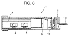
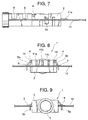
- the opto-electric common jack type connector 1 is fixed to the printed board 12 with a generally middle portion of the retainer 2 between an upper face and a lower face thereof being fitted in a cutaway portion formed in the printed board 12. That is, the thickness of the connector 1 mounted on the printed board 12 is only 4.2mm, as shown in Figs. 7 to 9, which is equal to the height of the retainer 2.
- the set total thickness of the connector 1 is smaller by the thickness of the board than the set total thickness of the conventional connector.
- the retainer 2 of the connector 1 is formed with two ribs on a right face and two ribs on a left face, a total of four ribs, which have been formed of a resin integrally with the retainer 2.
- portions 5a, 5b of the second terminal 5 of the connector 1 which are used to fix the connector 1 onto the printed board 12 each have a bent portion 14 (Fig. 3), and form a triangular configuration between the surface of the printed board 12 and the upper surface of the opto-electric common jack type connector 1.
- the second terminals 5, 6, 7, 8, 9 shown in Fig. 4 are each formed of a titanium-copper material which is superior in strength (e.g., rigidity) to the conventional material such as phosphor bronze.
- the second terminal 7 which is a movable terminal has been subjected to a quenching process. Since the second terminal 7 memorizes its initial shape, the second terminal 7 has a movability which is equivalent to that of the conventional movable terminal formed of phosphor bronze.
- the second terminals 5, 6, 7, 8, 9 of the connector 1 of Fig. 4 which are each formed of the titanium-copper material are less liable to be bent even if the optical signal transmission plug 101 (Fig. 17) or the electric signal transmission plug 111 (Fig. 18) is squeezed into or wrenched out of the connector 1 through an insertion port 3 of the connector 1 (Figs. 6 and 9).
- the connector 1 has a durability sufficient to withstand more than 5,000-time insertion and withdrawal. In addition, the fixing strength of the connector 1 with respect to the printed board 12 can be improved.
- the second terminals 5, 6, 7, 8, 9 typically have a thickness of 0.2mm or 0.25mm.
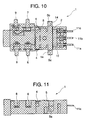
- the connector 1 has a resin coating formed on a cross-hatched portion thereof as seen in Figs. 10 and 11 by dipping the entire connector 1 in a fluororesin solution for a given period and drying the connector 1.
- the resin coating repels a soldering flux which is used when the connector 1 is fixed to the printed board 12 as shown in Figs. 7 to 9.
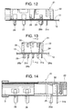
- the connector 21 shown in Figs. 12 to 14 is mounted on the printed board 12 with its second terminals 25, 26, 27, 28, 29 and first terminals 31a, 31b, 31c of an optical-to-electric converter 30 each extending straight from the bottom face of a retainer 22 perpendicularly to the surface of the board.
- the retainer 22 of the connector 21 is inverted with ribs 24 being located in different positions.
- the connector 21 shown in Figs. 12 to 14 is applicable to a non-portable digital audio system, a DVD player or the like which does not significantly require the size and thickness reduction thereof, and can firmly be fixed to the printed board.
- a fluororesin adhesive tape 13 is applied on the bottom face of the retainer 22 to prevent the soldering flux from creeping up into the connector 21 when the connector 21 is fixed to the printed board 12.
- the adhesive tape 13 forms a film repellent to the soldering flux between the printed board 12 and the opto-electric common jack type connector 21.
- solder flux will never creep up from the first terminals 31a, 31b, 31c nor from the second terminals 25, 26, 27, 28, 29.
- the use of the adhesive tape 13 is advantageous in that the connector 21 is applicable to a product which employs an IC chip, because the adhesive tape 13 is excellent in heat resistance, chemical resistance, water resistance and the like and is not static-prone.
- the connector 21 includes ribs 24 integrally formed with the retainer 22.
- the connector 21 is firmly fixed to the printed board 12.
- the connector 1 shown in Fig. 1 has a smaller size and thickness than the conventional connector, the connector 1 has substantially the same function as the conventional connector.
- the connector 1 is selectively connected to the optical signal transmission plug 101 shown in Fig. 17 and to the electric signal transmission plug 111 shown in Fig. 18 thereby to serve for the optical transmission as well as for the electrical transmission.
- the optical signal transmission plug 101 shown in Fig. 17 has substantially the same exterior configuration as the commercially available existing electric signal transmission plug 111 shown in Fig. 18.
- the optical signal transmission plug 101 includes a single head portion 102 and a base portion 103 which have the same shapes as those of the electric signal transmission plug 111, and further includes a neck portion 104 provided between the single head portion 102 and the base portion 103.
- a portion of the optical signal transmission plug 101 of Fig. 17 extending from the neck portion 104 to the base portion 103 is covered with an insulative resin portion 105.
- the optical signal transmission plug 101 is different from the electric signal transmission plug 111 shown in Fig. 18 in that the plug 101 does not have electrodes 116, 117, 118.
- the electric signal transmission plug 111 of Fig. 18 further includes annular insulating portions 112, 115 which electrically isolate the electrodes 116, 117, 118 from each other.
- the second terminals 5, 6, 7, 8, 9 of the connector are laid out as shown in Fig. 15. This allows for detection of insertion of the plug and identification of the inserted plug (i.e., the optical signal transmission plug 101 or the electric signal transmission plug 111).
- the second terminal 7 serves as a ground terminal which is connected to the ground (GND), and the second terminals 8, 9 are connected to a constant voltage power source Vref via resistor elements (pull-up resistors) R1 and R2, respectively, as shown in Fig. 15.
- resistor elements pulse-up resistors
- the second terminal 9 is disconnected from the second terminal 7, so that the voltage V 1 of the second terminal 9 is high.
- the detection of the plug is achieved by sensing the voltage V 1 of the second terminal 9 and determining the voltage level by means of an external system such as a microprocessor provided on a mount substrate.
- the identification of the inserted plug i.e., the optical signal transmission plug 101 or the electric signal transmission plug 111 can be achieved by sensing the voltage V 2 of the second terminal 8 and determining the voltage level by means of an external system such as a microprocessor provided on the mount substrate.
- the connector 21 shown in Figs. 12 to 14 also functions in the aforesaid manner.
- the set total thickness of the opto-electric common jack type connector mounted on the printed board can be reduced, and the fixing strength of the opto-electric common jack type connector with respect to the board can be improved.
Landscapes
- Physics & Mathematics (AREA)
- General Physics & Mathematics (AREA)
- Optics & Photonics (AREA)
- Coupling Device And Connection With Printed Circuit (AREA)
- Optical Couplings Of Light Guides (AREA)
- Connector Housings Or Holding Contact Members (AREA)
- Mechanical Coupling Of Light Guides (AREA)
- Light Receiving Elements (AREA)
- Details Of Connecting Devices For Male And Female Coupling (AREA)
Abstract
Description
Claims (8)
- An opto-electric common jack type connector adapted to be mounted on a printed board for selectively receiving an optical signal transmission plug and an electric signal transmission plug for connecting thereto, the jack type connector comprising:an optical-to-electric converter or an electric-to-optical converter which receives and transmits an optical signal from/to the optical signal transmission plug when the optical signal transmission plug is connected to the jack type connector;a first terminal extending from the converter and adapted to be fixed onto a surface of the printed board for receiving and transmitting an electric signal;a second terminal adapted to be fixed onto the surface of the printed board for receiving and transmitting an electric signal from/to the electric signal transmission plug when the electric signal transmission plug is connected to the jack type connector;a retainer holding the converter and the first and second terminals; anda plurality of ribs projecting from a peripheral portion of the retainer;
wherein the retainer is fitted in a cutaway portion formed in the printed board and having a configuration conformal to a profile of the retainer with the ribs abutting against the surface of the printed board for engagement with the printed board. - The opto-electric common jack type connector of claim 1, wherein at least one of the first terminal and the second terminal projects from the peripheral portion of the retainer so as to be brought into contact with the surface of the board when the retainer is fitted in the cutaway portion.
- The opto-electric common jack type connector of claim 1, wherein at least one of the first terminal and the second terminal projects from the peripheral portion of the retainer and includes a bent portion having an angle of greater than 90 degrees so that a distal end thereof is inserted through a hole formed in the board when the retainer is fitted in the cutaway portion.
- The opto-electric common jack type connector of claim 1, wherein the first and second terminals are formed of a titanium-copper material.
- The opto-electric common jack type connector of claim 1, wherein the first and second terminals are formed of a quenched titanium-copper material.
- The opto-electric common jack type connector of claim 1, wherein the jack type connector is coated with a coating resin before the jack type connector is fixed onto the circuitry of the printed board by soldering, so that a resin coating prevents a soldering flux from adhering onto an unintended portion of the jack type connector.
- The opto-electric common jack type connector of claim 1, wherein an adhesive tape is applied onto the retainer before the jack type connector is fixed onto the printed board by soldering, so that the tape prevents the soldering flux from adhering onto the unintended portion of the jack type connector.
- An opto-electric common jack type connector adapted to be mounted on a printed board for selectively receiving an optical signal transmission plug and an electric signal transmission plug for connecting thereto, the jack type connector comprising:an optical-to-electric converter or an electric-to-optical converter which receives and transmits an optical signal from/to the optical signal transmission plug when the optical signal transmission plug is connected to the jack type connector;a first terminal extending from the converter and adapted to be fixed onto a surface of the printed board for receiving and transmitting an electric signal;a second terminal adapted to be fixed onto the surface of the printed board for receiving and transmitting an electric signal from/to the electric signal transmission plug when the electric signal transmission plug is connected to the jack type connector;a retainer holding the converter and the first and second terminals; anda plurality of ribs projecting from a peripheral portion of the retainer;
wherein the ribs are adapted to abut against the surface of the board to prevent the retainer from tilting with respect to the board when the retainer is mounted onto the board.
Applications Claiming Priority (2)
| Application Number | Priority Date | Filing Date | Title |
|---|---|---|---|
| JP08888799A JP3445944B2 (en) | 1999-03-30 | 1999-03-30 | Jack type photoelectric sharing connection device |
| JP8888799 | 1999-03-30 |
Publications (3)
| Publication Number | Publication Date |
|---|---|
| EP1041412A2 true EP1041412A2 (en) | 2000-10-04 |
| EP1041412A3 EP1041412A3 (en) | 2003-04-02 |
| EP1041412B1 EP1041412B1 (en) | 2005-01-12 |
Family
ID=13955497
Family Applications (1)
| Application Number | Title | Priority Date | Filing Date |
|---|---|---|---|
| EP00103720A Expired - Lifetime EP1041412B1 (en) | 1999-03-30 | 2000-02-22 | Opto-electric common jack type connector |
Country Status (6)
| Country | Link |
|---|---|
| US (1) | US6238249B1 (en) |
| EP (1) | EP1041412B1 (en) |
| JP (1) | JP3445944B2 (en) |
| KR (1) | KR100334515B1 (en) |
| DE (1) | DE60017308T2 (en) |
| TW (1) | TW465144B (en) |
Cited By (1)
| Publication number | Priority date | Publication date | Assignee | Title |
|---|---|---|---|---|
| EP1203970A3 (en) * | 2000-11-01 | 2003-05-28 | Hosiden Corporation | Ultraminiature optical jack |
Families Citing this family (23)
| Publication number | Priority date | Publication date | Assignee | Title |
|---|---|---|---|---|
| JP3467460B2 (en) | 2000-09-05 | 2003-11-17 | シャープ株式会社 | Jack type photoelectric sharing connection device |
| JP2003186322A (en) | 2001-10-09 | 2003-07-04 | Canon Inc | Fixing device and image forming device |
| US20030142984A1 (en) * | 2002-01-25 | 2003-07-31 | Yoshifumi Masuda | Optical communication circuit chip, optical/electrical common transmission apparatus, optical transmission apparatus, and electric apparatus using same |
| TWM251361U (en) * | 2003-07-25 | 2004-11-21 | Hon Hai Prec Ind Co Ltd | Connector assembly |
| CN2689511Y (en) * | 2003-11-06 | 2005-03-30 | 富士康(昆山)电脑接插件有限公司 | Assembly of connector |
| CN2682647Y (en) * | 2003-11-19 | 2005-03-02 | 富士康(昆山)电脑接插件有限公司 | Connector assembly |
| CN100372187C (en) * | 2004-06-21 | 2008-02-27 | 宣得股份有限公司 | Connecting device with photoelectric detection function and using method thereof |
| US8183498B2 (en) * | 2006-05-01 | 2012-05-22 | Tcz, Llc | Systems and method for optimization of laser beam spatial intensity profile |
| JP4919340B2 (en) * | 2006-11-24 | 2012-04-18 | Fdk株式会社 | Winding parts |
| US7912501B2 (en) | 2007-01-05 | 2011-03-22 | Apple Inc. | Audio I/O headset plug and plug detection circuitry |
| US20080166908A1 (en) * | 2007-01-10 | 2008-07-10 | Speed Tech Corp. | Terminal positioning device for socket connector |
| US8651750B2 (en) * | 2009-11-19 | 2014-02-18 | Apple Inc. | Audio connectors with optical structures and electrical contacts |
| US8223986B2 (en) * | 2009-11-19 | 2012-07-17 | Apple Inc. | Electronic device and external equipment with digital noise cancellation and digital audio path |
| US8573861B2 (en) * | 2009-11-19 | 2013-11-05 | Apple Inc. | Audio jacks with optical and electrical paths |
| US8577195B2 (en) * | 2009-11-19 | 2013-11-05 | Apple Inc. | Interface accessories with optical and electrical paths |
| US8682003B2 (en) * | 2009-11-19 | 2014-03-25 | Apple Inc. | Equipment with optical paths for noise cancellation signals |
| US8718294B2 (en) * | 2009-11-19 | 2014-05-06 | Apple Inc. | Audio connectors with wavelength-division-multiplexing capabilities |
| US8620162B2 (en) | 2010-03-25 | 2013-12-31 | Apple Inc. | Handheld electronic device with integrated transmitters |
| KR101923472B1 (en) * | 2011-12-06 | 2018-11-29 | 엘지전자 주식회사 | Socket module and terminal having the same |
| US8568172B1 (en) * | 2012-04-12 | 2013-10-29 | Cheng Uei Precision Industry Co., Ltd. | Electrical connector |
| US20160339486A1 (en) * | 2015-05-21 | 2016-11-24 | Illinois Tool Works Inc. | Reflow oven liner, system and method |
| KR102314683B1 (en) * | 2017-07-12 | 2021-10-20 | 삼성전자주식회사 | Optical connector and control method of display apparatus |
| DE102024201702A1 (en) * | 2024-02-23 | 2025-08-28 | Zf Friedrichshafen Ag | Connector and printed circuit board with connector for automotive applications |
Family Cites Families (13)
| Publication number | Priority date | Publication date | Assignee | Title |
|---|---|---|---|---|
| JPS5141222B2 (en) * | 1972-12-06 | 1976-11-09 | ||
| US4548447A (en) * | 1984-04-05 | 1985-10-22 | Magnetic Controls Company | Electrical jack |
| US4880004A (en) | 1988-06-07 | 1989-11-14 | Intermedics, Inc. | Implantable cardiac stimulator with automatic gain control and bandpass filtering in feedback loop |
| US5167511A (en) * | 1990-11-27 | 1992-12-01 | Cray Research, Inc. | High density interconnect apparatus |
| JP3075306B2 (en) | 1990-12-26 | 2000-08-14 | オリンパス光学工業株式会社 | Bendable flexible tube |
| US5108317A (en) * | 1991-03-21 | 1992-04-28 | Amp Incorporated | Sealed metal shell connector and method of molding a plastic insert within a metal shell |
| US5685726A (en) * | 1992-07-17 | 1997-11-11 | Berg Technology, Inc. | Flat back card connector |
| JP3001750B2 (en) * | 1992-09-09 | 2000-01-24 | シャープ株式会社 | Plug / Jack type shared optical transmission equipment |
| US5338215A (en) * | 1993-03-19 | 1994-08-16 | Molex Incorporated | Jack assembly including a contact switching system |
| US5376022A (en) * | 1993-12-06 | 1994-12-27 | Safco Corporation | Electrical connector |
| US5823796A (en) * | 1996-04-02 | 1998-10-20 | Itt Manufacturing Enterprises, Inc. | Audio/power jack for IC card |
| US6116961A (en) * | 1998-11-12 | 2000-09-12 | Adc Telecommunications, Inc. | Jack assembly |
| US6126465A (en) * | 1999-01-25 | 2000-10-03 | Franks, Jr.; George J. | Electrical connector system having dual purpose jack |
-
1999
- 1999-03-30 JP JP08888799A patent/JP3445944B2/en not_active Expired - Fee Related
-
2000
- 2000-02-09 TW TW089102079A patent/TW465144B/en active
- 2000-02-22 EP EP00103720A patent/EP1041412B1/en not_active Expired - Lifetime
- 2000-02-22 DE DE60017308T patent/DE60017308T2/en not_active Expired - Lifetime
- 2000-03-07 US US09/520,322 patent/US6238249B1/en not_active Expired - Fee Related
- 2000-03-28 KR KR1020000015879A patent/KR100334515B1/en not_active Expired - Fee Related
Cited By (1)
| Publication number | Priority date | Publication date | Assignee | Title |
|---|---|---|---|---|
| EP1203970A3 (en) * | 2000-11-01 | 2003-05-28 | Hosiden Corporation | Ultraminiature optical jack |
Also Published As
| Publication number | Publication date |
|---|---|
| TW465144B (en) | 2001-11-21 |
| DE60017308D1 (en) | 2005-02-17 |
| JP3445944B2 (en) | 2003-09-16 |
| EP1041412B1 (en) | 2005-01-12 |
| KR100334515B1 (en) | 2002-04-26 |
| JP2000285996A (en) | 2000-10-13 |
| EP1041412A3 (en) | 2003-04-02 |
| KR20000063040A (en) | 2000-10-25 |
| DE60017308T2 (en) | 2005-12-22 |
| US6238249B1 (en) | 2001-05-29 |
Similar Documents
| Publication | Publication Date | Title |
|---|---|---|
| US6238249B1 (en) | Opto-electric common jack type connector | |
| US11631945B2 (en) | Connector assembly | |
| KR900008801Y1 (en) | Connector socket | |
| KR100319177B1 (en) | Plug-jack type transmitter and plug jack type photoelectric common transmitter | |
| US6648695B1 (en) | Electrical adapter for connecting connectors of different interface | |
| AU756003B2 (en) | Low crosstalk connector configuration | |
| US5310360A (en) | Circuit board mounted modular phone jack | |
| JPH058405B2 (en) | ||
| US7537488B2 (en) | Communication cable connector and communication cable | |
| CA2504858A1 (en) | Network connection sensing module | |
| US6948969B2 (en) | Electrical connector assembly with a cable guiding member | |
| EP1248325A2 (en) | Insulator coring and contact configuration to prevent pin stubbing in the throat of tuning fork socket connector contacts | |
| US4717344A (en) | Connector for circuit boards | |
| EP1037314B1 (en) | Receptacle and printed circuit assembly for receiving a plug | |
| JPS63226608A (en) | Optical connector | |
| US6994591B2 (en) | Electrical connector for use with flexible printed circuit | |
| EP0393251B1 (en) | Modular connector system with high contact element density surface mounted connectors | |
| JP3194215B2 (en) | Electrical connector assembly and method of adjusting its mating holding force | |
| JP2000252020A (en) | connector | |
| US6517252B2 (en) | Optical connector | |
| US6932642B2 (en) | Low insertion force connector | |
| US7154752B2 (en) | Optical module and optical hub system | |
| US20040043668A1 (en) | Shared electrical and optical transmission equipment of plug-and-jack type, and electronic device equipped therewith | |
| US6719590B1 (en) | Electrical adapter | |
| JP3292911B2 (en) | Cable connector |
Legal Events
| Date | Code | Title | Description |
|---|---|---|---|
| PUAI | Public reference made under article 153(3) epc to a published international application that has entered the european phase |
Free format text: ORIGINAL CODE: 0009012 |
|
| AK | Designated contracting states |
Kind code of ref document: A2 Designated state(s): AT BE CH CY DE DK ES FI FR GB GR IE IT LI LU MC NL PT SE |
|
| AX | Request for extension of the european patent |
Free format text: AL;LT;LV;MK;RO;SI |
|
| PUAL | Search report despatched |
Free format text: ORIGINAL CODE: 0009013 |
|
| AK | Designated contracting states |
Kind code of ref document: A3 Designated state(s): AT BE CH CY DE DK ES FI FR GB GR IE IT LI LU MC NL PT SE |
|
| AX | Request for extension of the european patent |
Extension state: AL LT LV MK RO SI |
|
| 17P | Request for examination filed |
Effective date: 20030808 |
|
| 17Q | First examination report despatched |
Effective date: 20030904 |
|
| AKX | Designation fees paid |
Designated state(s): DE NL |
|
| GRAP | Despatch of communication of intention to grant a patent |
Free format text: ORIGINAL CODE: EPIDOSNIGR1 |
|
| GRAS | Grant fee paid |
Free format text: ORIGINAL CODE: EPIDOSNIGR3 |
|
| GRAA | (expected) grant |
Free format text: ORIGINAL CODE: 0009210 |
|
| AK | Designated contracting states |
Kind code of ref document: B1 Designated state(s): DE NL |
|
| REF | Corresponds to: |
Ref document number: 60017308 Country of ref document: DE Date of ref document: 20050217 Kind code of ref document: P |
|
| REG | Reference to a national code |
Ref country code: IE Ref legal event code: FG4D |
|
| PLBE | No opposition filed within time limit |
Free format text: ORIGINAL CODE: 0009261 |
|
| STAA | Information on the status of an ep patent application or granted ep patent |
Free format text: STATUS: NO OPPOSITION FILED WITHIN TIME LIMIT |
|
| 26N | No opposition filed |
Effective date: 20051013 |
|
| PGFP | Annual fee paid to national office [announced via postgrant information from national office to epo] |
Ref country code: DE Payment date: 20100303 Year of fee payment: 11 |
|
| PGFP | Annual fee paid to national office [announced via postgrant information from national office to epo] |
Ref country code: NL Payment date: 20100218 Year of fee payment: 11 |
|
| REG | Reference to a national code |
Ref country code: NL Ref legal event code: V1 Effective date: 20110901 |
|
| PG25 | Lapsed in a contracting state [announced via postgrant information from national office to epo] |
Ref country code: NL Free format text: LAPSE BECAUSE OF NON-PAYMENT OF DUE FEES Effective date: 20110901 |
|
| REG | Reference to a national code |
Ref country code: DE Ref legal event code: R119 Ref document number: 60017308 Country of ref document: DE Effective date: 20110901 |
|
| PG25 | Lapsed in a contracting state [announced via postgrant information from national office to epo] |
Ref country code: DE Free format text: LAPSE BECAUSE OF NON-PAYMENT OF DUE FEES Effective date: 20110901 |