EP1041259A1 - Combustion chamber structure of in-cylinder direct fuel injection engine - Google Patents
Combustion chamber structure of in-cylinder direct fuel injection engine Download PDFInfo
- Publication number
- EP1041259A1 EP1041259A1 EP00302294A EP00302294A EP1041259A1 EP 1041259 A1 EP1041259 A1 EP 1041259A1 EP 00302294 A EP00302294 A EP 00302294A EP 00302294 A EP00302294 A EP 00302294A EP 1041259 A1 EP1041259 A1 EP 1041259A1
- Authority
- EP
- European Patent Office
- Prior art keywords
- cylinder
- axis
- piston
- center
- exhaust port
- Prior art date
- Legal status (The legal status is an assumption and is not a legal conclusion. Google has not performed a legal analysis and makes no representation as to the accuracy of the status listed.)
- Granted
Links
- 239000000446 fuel Substances 0.000 title claims abstract description 90
- 238000002485 combustion reaction Methods 0.000 title claims abstract description 39
- 238000002347 injection Methods 0.000 title claims abstract description 29
- 239000007924 injection Substances 0.000 title claims abstract description 29
- 230000002000 scavenging effect Effects 0.000 claims description 41
- 239000000203 mixture Substances 0.000 abstract description 16
- 239000007921 spray Substances 0.000 description 8
- 238000009792 diffusion process Methods 0.000 description 5
- 230000000630 rising effect Effects 0.000 description 5
- 238000000889 atomisation Methods 0.000 description 3
- 239000002826 coolant Substances 0.000 description 2
- 238000005461 lubrication Methods 0.000 description 2
- 230000007257 malfunction Effects 0.000 description 2
- OKTJSMMVPCPJKN-UHFFFAOYSA-N Carbon Chemical compound [C] OKTJSMMVPCPJKN-UHFFFAOYSA-N 0.000 description 1
- 229910052799 carbon Inorganic materials 0.000 description 1
- 230000006835 compression Effects 0.000 description 1
- 238000007906 compression Methods 0.000 description 1
- 238000001816 cooling Methods 0.000 description 1
- 238000007599 discharging Methods 0.000 description 1
- 238000001704 evaporation Methods 0.000 description 1
- 230000008020 evaporation Effects 0.000 description 1
- 238000000034 method Methods 0.000 description 1
- 238000012986 modification Methods 0.000 description 1
- 230000004048 modification Effects 0.000 description 1
- 230000001737 promoting effect Effects 0.000 description 1
- 230000000717 retained effect Effects 0.000 description 1
- 238000013517 stratification Methods 0.000 description 1
- 238000011144 upstream manufacturing Methods 0.000 description 1
- 238000009736 wetting Methods 0.000 description 1
Images




Classifications
-
- F—MECHANICAL ENGINEERING; LIGHTING; HEATING; WEAPONS; BLASTING
- F02—COMBUSTION ENGINES; HOT-GAS OR COMBUSTION-PRODUCT ENGINE PLANTS
- F02B—INTERNAL-COMBUSTION PISTON ENGINES; COMBUSTION ENGINES IN GENERAL
- F02B17/00—Engines characterised by means for effecting stratification of charge in cylinders
- F02B17/005—Engines characterised by means for effecting stratification of charge in cylinders having direct injection in the combustion chamber
-
- F—MECHANICAL ENGINEERING; LIGHTING; HEATING; WEAPONS; BLASTING
- F02—COMBUSTION ENGINES; HOT-GAS OR COMBUSTION-PRODUCT ENGINE PLANTS
- F02B—INTERNAL-COMBUSTION PISTON ENGINES; COMBUSTION ENGINES IN GENERAL
- F02B23/00—Other engines characterised by special shape or construction of combustion chambers to improve operation
- F02B23/08—Other engines characterised by special shape or construction of combustion chambers to improve operation with positive ignition
- F02B23/10—Other engines characterised by special shape or construction of combustion chambers to improve operation with positive ignition with separate admission of air and fuel into cylinder
- F02B23/104—Other engines characterised by special shape or construction of combustion chambers to improve operation with positive ignition with separate admission of air and fuel into cylinder the injector being placed on a side position of the cylinder
-
- F—MECHANICAL ENGINEERING; LIGHTING; HEATING; WEAPONS; BLASTING
- F02—COMBUSTION ENGINES; HOT-GAS OR COMBUSTION-PRODUCT ENGINE PLANTS
- F02B—INTERNAL-COMBUSTION PISTON ENGINES; COMBUSTION ENGINES IN GENERAL
- F02B23/00—Other engines characterised by special shape or construction of combustion chambers to improve operation
- F02B23/08—Other engines characterised by special shape or construction of combustion chambers to improve operation with positive ignition
- F02B23/10—Other engines characterised by special shape or construction of combustion chambers to improve operation with positive ignition with separate admission of air and fuel into cylinder
- F02B2023/106—Tumble flow, i.e. the axis of rotation of the main charge flow motion is horizontal
- F02B2023/107—Reverse tumble flow, e.g. having substantially vertical intake ports
-
- F—MECHANICAL ENGINEERING; LIGHTING; HEATING; WEAPONS; BLASTING
- F02—COMBUSTION ENGINES; HOT-GAS OR COMBUSTION-PRODUCT ENGINE PLANTS
- F02B—INTERNAL-COMBUSTION PISTON ENGINES; COMBUSTION ENGINES IN GENERAL
- F02B75/00—Other engines
- F02B75/02—Engines characterised by their cycles, e.g. six-stroke
- F02B2075/022—Engines characterised by their cycles, e.g. six-stroke having less than six strokes per cycle
- F02B2075/025—Engines characterised by their cycles, e.g. six-stroke having less than six strokes per cycle two
-
- F—MECHANICAL ENGINEERING; LIGHTING; HEATING; WEAPONS; BLASTING
- F02—COMBUSTION ENGINES; HOT-GAS OR COMBUSTION-PRODUCT ENGINE PLANTS
- F02B—INTERNAL-COMBUSTION PISTON ENGINES; COMBUSTION ENGINES IN GENERAL
- F02B75/00—Other engines
- F02B75/12—Other methods of operation
- F02B2075/125—Direct injection in the combustion chamber for spark ignition engines, i.e. not in pre-combustion chamber
-
- F—MECHANICAL ENGINEERING; LIGHTING; HEATING; WEAPONS; BLASTING
- F02—COMBUSTION ENGINES; HOT-GAS OR COMBUSTION-PRODUCT ENGINE PLANTS
- F02B—INTERNAL-COMBUSTION PISTON ENGINES; COMBUSTION ENGINES IN GENERAL
- F02B2275/00—Other engines, components or details, not provided for in other groups of this subclass
- F02B2275/48—Tumble motion in gas movement in cylinder
-
- F—MECHANICAL ENGINEERING; LIGHTING; HEATING; WEAPONS; BLASTING
- F02—COMBUSTION ENGINES; HOT-GAS OR COMBUSTION-PRODUCT ENGINE PLANTS
- F02B—INTERNAL-COMBUSTION PISTON ENGINES; COMBUSTION ENGINES IN GENERAL
- F02B23/00—Other engines characterised by special shape or construction of combustion chambers to improve operation
- F02B23/08—Other engines characterised by special shape or construction of combustion chambers to improve operation with positive ignition
- F02B23/10—Other engines characterised by special shape or construction of combustion chambers to improve operation with positive ignition with separate admission of air and fuel into cylinder
- F02B23/101—Other engines characterised by special shape or construction of combustion chambers to improve operation with positive ignition with separate admission of air and fuel into cylinder the injector being placed on or close to the cylinder centre axis, e.g. with mixture formation using spray guided concepts
-
- F—MECHANICAL ENGINEERING; LIGHTING; HEATING; WEAPONS; BLASTING
- F02—COMBUSTION ENGINES; HOT-GAS OR COMBUSTION-PRODUCT ENGINE PLANTS
- F02F—CYLINDERS, PISTONS OR CASINGS, FOR COMBUSTION ENGINES; ARRANGEMENTS OF SEALINGS IN COMBUSTION ENGINES
- F02F3/00—Pistons
- F02F3/26—Pistons having combustion chamber in piston head
-
- Y—GENERAL TAGGING OF NEW TECHNOLOGICAL DEVELOPMENTS; GENERAL TAGGING OF CROSS-SECTIONAL TECHNOLOGIES SPANNING OVER SEVERAL SECTIONS OF THE IPC; TECHNICAL SUBJECTS COVERED BY FORMER USPC CROSS-REFERENCE ART COLLECTIONS [XRACs] AND DIGESTS
- Y02—TECHNOLOGIES OR APPLICATIONS FOR MITIGATION OR ADAPTATION AGAINST CLIMATE CHANGE
- Y02T—CLIMATE CHANGE MITIGATION TECHNOLOGIES RELATED TO TRANSPORTATION
- Y02T10/00—Road transport of goods or passengers
- Y02T10/10—Internal combustion engine [ICE] based vehicles
- Y02T10/12—Improving ICE efficiencies
Definitions
- the present invention relates to a structure of a combustion chamber for an in-cylinder fuel injection engine in which fuel is injected directly into the cylinder.
- the engine employing the stratified charge combustion strategy has an excellent fuel economy performance.
- An engine 1 shown in Fig. 8 is an example of an in-cylinder fuel injection two cycle engine intended to realize the stratified charge combustion according to the prior art.
- the engine 1 comprises a cylinder block 3 having a cylinder 2, a piston 4 reciprocating in the cylinder 2 and a cylinder head 5.
- a combustion chamber is formed by the cylinder 1, the top surface of the piston 4 and the cylinder head 5.
- a cavity 4a is formed on the top surface of the piston 4, a fuel injector 6 is disposed approximately coaxially with the center line CL of the cylinder bore, and a spark plug 7 is disposed slightly diagonally in the vicinity of the fuel injector 6.
- booster port 2a There are provided a booster port 2a, a scavenging port 2b and an exhaust port 2c on the wall surface of the cylinder 2 and these ports are opened and closed respectively by the reciprocating motion of the piston 4.
- the booster port 2a and the scavenging port 2b are ports for introducing a fresh air including lubrication oil into the cylinder 2.
- the exhaust port 2c is a passage for discharging exhaust gas therethrough and it is provided opposite to the booster port 2a.
- the spark plug 7 ignites the rear end of the fuel spray in a first stage diffusion.
- the fuel spray in the first stage diffusion is a fuel at a stage of diffusing and not reaching the top surface of the rising piston 4.
- the fuel injector 6 is close to the spark plug 7, so that the rear end of the sprayed fuel is ignited by the spark plug 7 before the sprayed fuel collides with the top surface of the rising piston 4.
- This disposition of the spark plug 7 adjacent to the fuel injector 6 incurs a temperature-rise of the fuel injector 6 itself, this causing the malfunction of the fuel injector 6, an increase of carbon deposits and the like.
- the ignition of the fuel spray in the first stage diffusion tends to provide an inadequate atomization in the sprayed fuel and this inadequate atomization causes a wetting in the spark plug 7, this often leading to a spark plug fouling.
- supposing a case of the ignition of the fuel spray in a second stage diffusion that is, a state of the fuel spray after a collision against the piston 4, since the flow of scavenging acts as carrying the fuel spray away from the spark plug 7, this strategy of combustion makes it difficult to realize the stratified charge combustion.
- an in-cylinder fuel injection engine having a cylinder, a piston movably disposed in the cylinder for reciprocal motion, a cylinder head secured over the cylinder and piston to form a combustion chamber, an exhaust port, a booster port disposed on an opposite side of the exhaust port with respect to a cylinder bore center axis to strengthen a scavenging flow of fresh air, a plurality of scavenging ports arranged symmetrically with respect to a first axis connecting a center of the exhaust port with a center of the booster port, a spark plug mounted in the cylinder head and a fuel injector mounted in the cylinder head to inject a fuel into the cylinder, comprises a piston cavity having a concavely spherical surface and disposed on a top surface of the piston such that a center of the piston cavity is located approximately on the first axis in an offset position on the exhaust port side, a combustion chamber dome disposed opposite to the piston cavity at the back surface of the cylinder head, an electrode of the
- reference numeral 10 denotes an in-cylinder direct fuel injection 2-cycle engine introducing a reverse scavenging flow method.
- the engine 10 comprises a cylinder block 12 having a cylinder 11, a piston 13 reciprocating in the cylinder 11 and a cylinder head 14 which forms a combustion chamber together with the cylinder 11 and the top of the piston 13.
- a booster port 11a There are provided a booster port 11a, a plurality of scavenging ports 11b and an exhaust port 11c, which open and close by the reciprocating motion of the piston 13, in the wall of the cylinder 11. Further, the exhaust port 11c and the booster port 11a are disposed in diametrically opposed locations of the cylinder. The exhaust port 11c is located slightly higher than the booster port 11a. Further, as shown in Fig. 2, the scavenging ports 11b are arranged in a bilaterally symmetrical manner with respect to an axis L1 connecting the booster port 11a with the exhaust port 11c. In this case, the booster port 11a is one of scavenging ports and acts as promoting an inverse tumble flow (see Fig. 3a) of the fresh air in the cylinder 11.
- the booster port 11a is located at approximately the same level as the scavenging ports 11b and these ports 11a, 11b communicate with a crankcase (not shown) formed in the lower part of the cylinder block 12. Also, an intake port (not shown) communicates with the crankcase to introduce the fresh air including lubrication oil into the crankcase. The fresh air introduced into the crankcase is fed to the combustion chamber 22 through the booster port 11a and scavenging ports 11b.
- the top of the piston 13 is shaped convexly and further a concave piston cavity 13a is formed with a spherical wall surface 13b on a part of that convex surface.
- the piston cavity 13a is shaped round when viewed from top.
- the center of the piston cavity 13a is located approximately on the axis L1 when viewed from top and is slightly offset on the exhaust port 11c side with respect to a cylinder bore center line CL.
- the cylinder head 14 is mounted on the cylinder block 12 and secured thereto by a plurality of bolts (not shown).
- a squish area 14a is formed along the top surface of the piston 13 and a combustion chamber dome 14b having a spherical surface is provided at a position opposite to the piston cavity 13a.
- the center of the dome 14b approximately coincides with the center axis of the piston cavity 13a, when viewed from top. Further, the diameter of the edge circle of the dome 14b is designed so as to be slightly larger than that of the edge circle of the piston cavity 13a.
- a spark plug bore 17 is provided in the cylinder head 14 such that an electrode 16 of a spark plug 15 is positioned on the cylinder bore center CL.
- a fuel injector bore 19 for mounting a fuel injector 18 is provided at the outer periphery edge of the dome 14b on the exhaust port side 11c so as to obtain a maximal distance between the spark plug 15 and the fuel injector 18 in the dome 14b. That is, an injection nozzle of the fuel injector 18 is positioned approximately at a point of intersection of the outer periphery edge of the dome 14b and the axis L1 connecting the center of the booster port 11a with the center of the exhaust port 11c.
- the fuel injector bore 19 is bored such that the fuel is injected toward the booster port 11a.
- the fuel is sprayed along the spherical wall surface 13b of the piston cavity 13a.
- the spark plug 15 is threaded into the spark plug bore 17 and the fuel injector 18 is mounted onto the fuel injector bore 19.
- the fuel injector 18 is controlled by a control section (not shown) so as to inject fuel into the combustion chamber based on the fuel injection amount and the fuel injection time which are optimally determined according to engine loads and engine speeds.
- a plurality of coolant passages 20 are provided in the cylinder head 14 so as to circulate therethrough for the purpose of cooling the cylinder wall 11 and the combustion chamber.
- the fresh air is compressed by the squish area 14a, the dome 14b, the cylinder 11 and the piston cavity 13a of the rising piston 13 and then the fuel is injected towards the compressed fresh air.
- the sprayed fuel collides against the wall surface 13b of the piston cavity 13a, it goes upward along the wall surface 13b and forms a locally combustible mixture in the combustion chamber.
- the spark plug 15 ignites thus formed combustible mixture, the combustion expands to overall mixture layers, the stratified charge combustion being accomplished.
- the fuel is optimized in the fuel injection amount and the fuel injection time and is injected toward the piston cavity 13a of the rising piston 13 (Fig. 3b).
- the sprayed fuel collides with the piston cavity 13a, travels upward along the surface configuration of the piston cavity 13a while it is mixed with the reverse tumble flow of the fresh air (Fig. 3c), and reaches immediately beneath the electrode 16 of the spark plug 15 to form a locally rich (stratified) and combustible mixture in the vicinity of the spark plug 15 (Fig. 3d).
- the skirt of the piston 13 starts to open the intake port to introduce the fresh air.
- the piston 13 further continues to rise and comes close to the top dead center.
- the mixture is ignited by the electrode 16 of the spark plug 15.
- the ignitablity is enhanced, thereby a good stratified charge combustion can be secured.
- the spark plug 15 is located as far from the fuel injector 18 as possible in the dome 14b, the fuel injector 18 can be less affected by heat from the spark plug 15.
- the combustion strategy changes from the stratified charge combustion to the homogeneous charge combustion.
- the fuel injector 18 is directed to the booster port 11a and the scavenging ports 11b, it is possible to inject fuel toward the upstream of the incoming fresh air and as a result it is possible to make more time for diffusion, evaporation and atomization of the injected fuel.
- the fuel injector 18 is arranged above the exhaust port 11c and extends in the same direction as the exhaust port 11c, the fuel injector 18 is easily influenced by heat.
- the second embodiment contemplates to reduce the influence of heat on the fuel injector 18 by arranging the fuel injector 18 as apart from the exhaust port 11c as possible.
- the piston 13' has a piston cavity 13a' in an offset position on the exhaust port 11c side with respect to the cylinder bore center CL and on the upper side with respect to the axis L1.
- an angle ⁇ contained by the axes L1 and L2 is within a range of 0 ⁇ ⁇ ⁇ 90 degrees.
- the angle ⁇ is more preferably 30 degrees or thereabout, in consideration of a degree of freedom in designing a cylinder head 14'.
- the piston cavity 13a' has the same configuration as the piston cavity 13a of the first embodiment.
- Fig. 5 shows an undersuface of the cylinder head 14' which is mounted on the cylinder block 12.
- a dome 14b' in a squish area 14a' of the cylinder head 14'.
- the dome 14b' is positioned opposite to the piston cavity 13a'and its center is located on the axis L2 meeting the axis L1 at an angle ⁇ .
- an injector bore 19 is provided approximately at a point of intersection of the axis L1 and the outer periphery edge of the dome 14b' such that the fuel spray from the fuel injector 18 threaded into the injector bore 19 is directed to the wall surface 13b' of the piston cavity 13a'.
- a spark plug bore 17 is provided in the dome 14b'in the vicinity of the cylinder bore center axis CL such that the electrode 16 of the spark plug 15 threaded into the spark plug bore 17 is positioned approximately on the cylinder bore center axis CL.
- reference numeral 20 denotes coolant passages and numeral 21 denotes bolt through holes for the tightening bolts 21 of the cylinder head 14'.
- the reverse tumble flow is generated, the sprayed fuel travels upwards along the spherical wall surface 13b' toward the cylinder bore center axis CL and the rich, combustible mixture is formed in the vicinity of the spark plug 15.
- the mixture is ignited by the spark plug 15 to make the stratified charge combustion.
- the fuel injector 18 can be mounted as apart from the exhaust port 11c as possible. This can protect the fuel injector 18 from being heated by the exhaust port 11c.
- a plurality of scavenging ports 11b are formed on the wall surface of the cylinder block 12 in a bilaterally symmetrical manner with respect to the axis L1.
- the symmetrical structure of the scavenging ports does not always provide a stable scavenging flow around the spark plug 15.
- the third embodiment contemplates to form a stable scavenging flow in the vicinity of the spark plug 15.
- a plurality of scavenging ports 11b are disposed on the upper side of the axis L1 and a plurality of scavenging ports 11d are disposed on the lower side of the axis L1.
- the scavenging ports 11b are in an unsymmetrical relationship with the scavenging ports 11d. That is, the opening area of the scavenging ports 11d is larger (or smaller) than that of the scavenging ports 11b and the discharge direction of the scavenging ports 11d are different from that of the scavenging ports 11b.
- the scavenging flow introduced into the cylinder 11 from thus unsymmetrically disposed scavenging ports has a definite directivity and, as a result, when the fuel injector 18 injects fuel toward the scavenging flow, a steady combustible mixture can be formed securedly in the vicinity of the spark plug 15.
- the piston 13 has the piston cavity 13a shaped into a spherical surface 13b.
- the piston cavity 13a' is shaped partially into a spherical surface and partially into a steep cliff. That is, the piston cavity 13a' according to the fourth embodiment is shaped into a spherical surface from the outer periphery edge to the central part of the piston 13 and a steep cliff 13b' at the central part of the piston 13.
- the steep cliff 13b' has a more definite directivity toward the electrode 16 of the spark plug 15 than the spherical surface 13b of the first embodiment. That is, since the fuel spray is concentratedly guided by the steep cliff 13b' toward the electrode 16, a rich mixture can be more easily formed around the electrode 16. In other words, the magnitude of the stratification of mixture can be intensified.
Landscapes
- Engineering & Computer Science (AREA)
- Chemical & Material Sciences (AREA)
- Combustion & Propulsion (AREA)
- Mechanical Engineering (AREA)
- General Engineering & Computer Science (AREA)
- Combustion Methods Of Internal-Combustion Engines (AREA)
Abstract
Description
- The present invention relates to a structure of a combustion chamber for an in-cylinder fuel injection engine in which fuel is injected directly into the cylinder.
- Generally, since the stratified charge combustion strategy provides a readily ignitable rich air-fuel mixture in the vicinity of the spark plug with the overall air-fuel ratio retained in the lean condition, the engine employing the stratified charge combustion strategy has an excellent fuel economy performance.
- An
engine 1 shown in Fig. 8 is an example of an in-cylinder fuel injection two cycle engine intended to realize the stratified charge combustion according to the prior art. Theengine 1 comprises acylinder block 3 having acylinder 2, apiston 4 reciprocating in thecylinder 2 and acylinder head 5. A combustion chamber is formed by thecylinder 1, the top surface of thepiston 4 and thecylinder head 5. - A
cavity 4a is formed on the top surface of thepiston 4, afuel injector 6 is disposed approximately coaxially with the center line CL of the cylinder bore, and aspark plug 7 is disposed slightly diagonally in the vicinity of thefuel injector 6. - There are provided a
booster port 2a, ascavenging port 2b and anexhaust port 2c on the wall surface of thecylinder 2 and these ports are opened and closed respectively by the reciprocating motion of thepiston 4. Thebooster port 2a and thescavenging port 2b are ports for introducing a fresh air including lubrication oil into thecylinder 2. Theexhaust port 2c is a passage for discharging exhaust gas therethrough and it is provided opposite to thebooster port 2a. - In this type of the combustion chamber, the
spark plug 7 ignites the rear end of the fuel spray in a first stage diffusion. The fuel spray in the first stage diffusion is a fuel at a stage of diffusing and not reaching the top surface of the risingpiston 4. - As described before, according to this prior art, the
fuel injector 6 is close to thespark plug 7, so that the rear end of the sprayed fuel is ignited by thespark plug 7 before the sprayed fuel collides with the top surface of the risingpiston 4. This disposition of thespark plug 7 adjacent to thefuel injector 6 incurs a temperature-rise of thefuel injector 6 itself, this causing the malfunction of thefuel injector 6, an increase of carbon deposits and the like. - Further, the ignition of the fuel spray in the first stage diffusion tends to provide an inadequate atomization in the sprayed fuel and this inadequate atomization causes a wetting in the
spark plug 7, this often leading to a spark plug fouling. Further, supposing a case of the ignition of the fuel spray in a second stage diffusion, that is, a state of the fuel spray after a collision against thepiston 4, since the flow of scavenging acts as carrying the fuel spray away from thespark plug 7, this strategy of combustion makes it difficult to realize the stratified charge combustion. - It is an object of the present invention to provide a combustion chamber structure of an in-cylinder direct fuel injection engine capable of realizing the stratified charge combustion and it is a further object of the present invention to provide an internal combustion engine free from serious malfunctions like misfires.
- To attain these objects, an in-cylinder fuel injection engine having a cylinder, a piston movably disposed in the cylinder for reciprocal motion, a cylinder head secured over the cylinder and piston to form a combustion chamber, an exhaust port, a booster port disposed on an opposite side of the exhaust port with respect to a cylinder bore center axis to strengthen a scavenging flow of fresh air, a plurality of scavenging ports arranged symmetrically with respect to a first axis connecting a center of the exhaust port with a center of the booster port, a spark plug mounted in the cylinder head and a fuel injector mounted in the cylinder head to inject a fuel into the cylinder, comprises a piston cavity having a concavely spherical surface and disposed on a top surface of the piston such that a center of the piston cavity is located approximately on the first axis in an offset position on the exhaust port side,
a combustion chamber dome disposed opposite to the piston cavity at the back surface of the cylinder head, an electrode of the spark plug positioned in vicinity of the cylinder bore center axis and an injection nozzle of the fuel injector positioned approximately at a point of intersection of the first axis and an outer periphery edge line of the dome. -
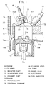
- Fig. 1 is a side cross sectional view of an in-cylinder direct fuel injection 2-cycle engine according to a first embodiment of the present invention;
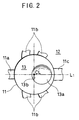
- Fig. 2 is a partially top view of the engine shown in Fig. 1;
- Fig. 3a is an explanatory view showing a flow of scavenging air when scavenging ports are opened;
- Fig. 3b is an explanatory view showing a state of a fuel injected from a fuel injector toward a piston cavity when a piston comes near the top dead center;
- Fig. 3c is an explanatory view showing a state of a fuel going upward while being mixed with the fresh air;
- Fig. 3d is an explanatory view showing a state of a fuel stratified around a spark plug;
- Fig. 4 is a partially top view of an in-cylinder direct fuel injection 2-cycle engine according to a second embodiment of the present invention;
- Fig. 5 is a bottom view of a cylinder head of the engine according to the second embodiment;
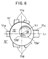
- Fig. 6 is a partially top view of an in-cylinder direct fuel injection 2-cycle engine according to a third embodiment of the present invention;
- Fig. 7 is a side cross sectional view of an in-cylinder direct fuel injection 2-cycle engine according to a fourth embodiment of the present invention; and
- Fig. 8 is a side cross sectional view of an in-cylinder direct fuel injection 2-cycle engine according to a prior art.
-
- Referring now to Fig. 1,
reference numeral 10 denotes an in-cylinder direct fuel injection 2-cycle engine introducing a reverse scavenging flow method. Theengine 10 comprises acylinder block 12 having acylinder 11, apiston 13 reciprocating in thecylinder 11 and acylinder head 14 which forms a combustion chamber together with thecylinder 11 and the top of thepiston 13. - There are provided a
booster port 11a, a plurality ofscavenging ports 11b and anexhaust port 11c, which open and close by the reciprocating motion of thepiston 13, in the wall of thecylinder 11. Further, theexhaust port 11c and thebooster port 11a are disposed in diametrically opposed locations of the cylinder. Theexhaust port 11c is located slightly higher than thebooster port 11a. Further, as shown in Fig. 2, thescavenging ports 11b are arranged in a bilaterally symmetrical manner with respect to an axis L1 connecting thebooster port 11a with theexhaust port 11c. In this case, thebooster port 11a is one of scavenging ports and acts as promoting an inverse tumble flow (see Fig. 3a) of the fresh air in thecylinder 11. - Further, the
booster port 11a is located at approximately the same level as thescavenging ports 11b and theseports cylinder block 12. Also, an intake port (not shown) communicates with the crankcase to introduce the fresh air including lubrication oil into the crankcase. The fresh air introduced into the crankcase is fed to thecombustion chamber 22 through thebooster port 11a and scavengingports 11b. - As illustrated in Fig. 1, the top of the
piston 13 is shaped convexly and further aconcave piston cavity 13a is formed with aspherical wall surface 13b on a part of that convex surface. Thepiston cavity 13a is shaped round when viewed from top. The center of thepiston cavity 13a is located approximately on the axis L1 when viewed from top and is slightly offset on theexhaust port 11c side with respect to a cylinder bore center line CL. - The
cylinder head 14 is mounted on thecylinder block 12 and secured thereto by a plurality of bolts (not shown). - On the back surface of the
cylinder head 14, asquish area 14a is formed along the top surface of thepiston 13 and acombustion chamber dome 14b having a spherical surface is provided at a position opposite to thepiston cavity 13a. - The center of the
dome 14b approximately coincides with the center axis of thepiston cavity 13a, when viewed from top. Further, the diameter of the edge circle of thedome 14b is designed so as to be slightly larger than that of the edge circle of thepiston cavity 13a. - Further, a
spark plug bore 17 is provided in thecylinder head 14 such that anelectrode 16 of aspark plug 15 is positioned on the cylinder bore center CL. Further, a fuel injector bore 19 for mounting afuel injector 18 is provided at the outer periphery edge of thedome 14b on theexhaust port side 11c so as to obtain a maximal distance between thespark plug 15 and thefuel injector 18 in thedome 14b. That is, an injection nozzle of thefuel injector 18 is positioned approximately at a point of intersection of the outer periphery edge of thedome 14b and the axis L1 connecting the center of thebooster port 11a with the center of theexhaust port 11c. - Further, the
fuel injector bore 19 is bored such that the fuel is injected toward thebooster port 11a. On an actual fuel injection, since the fuel is injected at the latter period of the compression stroke, the fuel is sprayed along thespherical wall surface 13b of thepiston cavity 13a. - The
spark plug 15 is threaded into thespark plug bore 17 and thefuel injector 18 is mounted onto thefuel injector bore 19. Thefuel injector 18 is controlled by a control section (not shown) so as to inject fuel into the combustion chamber based on the fuel injection amount and the fuel injection time which are optimally determined according to engine loads and engine speeds. Further, a plurality ofcoolant passages 20 are provided in thecylinder head 14 so as to circulate therethrough for the purpose of cooling thecylinder wall 11 and the combustion chamber. - In thus constituted
engine 10, the fresh air is compressed by thesquish area 14a, thedome 14b, thecylinder 11 and thepiston cavity 13a of the risingpiston 13 and then the fuel is injected towards the compressed fresh air. The sprayed fuel collides against thewall surface 13b of thepiston cavity 13a, it goes upward along thewall surface 13b and forms a locally combustible mixture in the combustion chamber. When thespark plug 15 ignites thus formed combustible mixture, the combustion expands to overall mixture layers, the stratified charge combustion being accomplished. - In operation of thus constituted
engine 10, when thepiston 13 goes down from the top dead center toward the bottom dead center, first the top of thedescending piston 13 opens theexhaust port 11c to discharge exhaust gas. Next, thepiston 13 opens thebooster port 11a and the scavengingport 11b which are located slightly below theexhaust port 11c. At this moment, the fresh air compressed within the crankcase is sent into thecylinder 11 through thebooster port 11a and the scavengingport 11b to fill thecylinder 11 while it squeezes the residual exhaust gas out of thecylinder 11 through theexhaust port 11c. - This scavenging operation continues due to the inertia force of the incoming fresh air until the
booster port 11a and the scavengingport 11b are closed by the top surface of the risingpiston 13. When thepiston 13 closes theexhaust port 11c, a reverse tumble flow of the fresh air is generated in the cylinder 11 (Fig. 3a). - Further, when the
piston 13 continues to rise toward the top dead center after the respective ports are closed, the fuel is optimized in the fuel injection amount and the fuel injection time and is injected toward thepiston cavity 13a of the rising piston 13 (Fig. 3b). The sprayed fuel collides with thepiston cavity 13a, travels upward along the surface configuration of thepiston cavity 13a while it is mixed with the reverse tumble flow of the fresh air (Fig. 3c), and reaches immediately beneath theelectrode 16 of thespark plug 15 to form a locally rich (stratified) and combustible mixture in the vicinity of the spark plug 15 (Fig. 3d). At this moment, the skirt of thepiston 13 starts to open the intake port to introduce the fresh air. - The
piston 13 further continues to rise and comes close to the top dead center. At an optimum timing before thepiston 13 reaches the top dead center, the mixture is ignited by theelectrode 16 of thespark plug 15. At this moment, since the rich, combustible mixture is formed around theelectrode 16, the ignitablity is enhanced, thereby a good stratified charge combustion can be secured. - Further, when the combustible mixture is ignited, since the
electrode 16 is positioned approximately on the cylinder bore center line CL, the combustion speed of the combustible mixture can be increased and as a result the combustion time can be reduced. Further, since thespark plug 15 is located as far from thefuel injector 18 as possible in thedome 14b, thefuel injector 18 can be less affected by heat from thespark plug 15. - When thus ignited mixture is burned in the
combustion chamber 22, the high pressure gas generated by the combustion pushes thepiston 13 downward, thereby the aforesaid cycle is repeated. The movement of thepiston 13 is transmitted to a crank shaft (not shown) from which the rotational force is produced. - When the
engine 10 is operated in a high load condition, the combustion strategy changes from the stratified charge combustion to the homogeneous charge combustion. Under this condition, since thefuel injector 18 is directed to thebooster port 11a and the scavengingports 11b, it is possible to inject fuel toward the upstream of the incoming fresh air and as a result it is possible to make more time for diffusion, evaporation and atomization of the injected fuel. - Next, an engine according to a second embodiment of the present invention will be described by reference to Figs. 4 and 5.
- According to the first embodiment, as described before, since the
fuel injector 18 is arranged above theexhaust port 11c and extends in the same direction as theexhaust port 11c, thefuel injector 18 is easily influenced by heat. - To solve this problem, the second embodiment contemplates to reduce the influence of heat on the
fuel injector 18 by arranging thefuel injector 18 as apart from theexhaust port 11c as possible. - Referring to Fig. 4, the piston 13' has a
piston cavity 13a' in an offset position on theexhaust port 11c side with respect to the cylinder bore center CL and on the upper side with respect to the axis L1. Assuming an axis L2 connecting the cylinder bore center CL with a center of thepiston cavity 13a', an angle contained by the axes L1 and L2 is within a range of 0 < < 90 degrees. The angle is more preferably 30 degrees or thereabout, in consideration of a degree of freedom in designing a cylinder head 14'. Thepiston cavity 13a' has the same configuration as thepiston cavity 13a of the first embodiment. - Fig. 5 shows an undersuface of the cylinder head 14' which is mounted on the
cylinder block 12. In the drawing, there is provided adome 14b' in asquish area 14a' of the cylinder head 14'. Thedome 14b' is positioned opposite to the piston cavity 13a'and its center is located on the axis L2 meeting the axis L1 at an angle . Further, an injector bore 19 is provided approximately at a point of intersection of the axis L1 and the outer periphery edge of thedome 14b' such that the fuel spray from thefuel injector 18 threaded into the injector bore 19 is directed to thewall surface 13b' of thepiston cavity 13a'. - Further, a spark plug bore 17 is provided in the dome 14b'in the vicinity of the cylinder bore center axis CL such that the
electrode 16 of thespark plug 15 threaded into the spark plug bore 17 is positioned approximately on the cylinder bore center axis CL. In the drawing,reference numeral 20 denotes coolant passages and numeral 21 denotes bolt through holes for the tighteningbolts 21 of the cylinder head 14'. - In the combustion chamber thus constituted, in the same manner as in the first embodiment, the reverse tumble flow is generated, the sprayed fuel travels upwards along the
spherical wall surface 13b' toward the cylinder bore center axis CL and the rich, combustible mixture is formed in the vicinity of thespark plug 15. The mixture is ignited by thespark plug 15 to make the stratified charge combustion. - On the other hand, since the centers of the
piston cavity 13a' and the dome 14b'are offset from the axis L1 respectively, thefuel injector 18 can be mounted as apart from theexhaust port 11c as possible. This can protect thefuel injector 18 from being heated by theexhaust port 11c. - Next, a third embodiment of the present invention will be described by reference to Fig. 6.
- Generally, a plurality of scavenging
ports 11b are formed on the wall surface of thecylinder block 12 in a bilaterally symmetrical manner with respect to the axis L1. When the actual scavenging flow is visualized, it is appreciated that the scavenging flow sometimes suddenly starts to rotate in a certain direction and sometimes suddenly starts to rotate in a reverse direction. Therefore, the symmetrical structure of the scavenging ports does not always provide a stable scavenging flow around thespark plug 15. - The third embodiment contemplates to form a stable scavenging flow in the vicinity of the
spark plug 15. - Referring to Fig. 6, a plurality of scavenging
ports 11b are disposed on the upper side of the axis L1 and a plurality of scavengingports 11d are disposed on the lower side of the axis L1. The scavengingports 11b are in an unsymmetrical relationship with the scavengingports 11d. That is, the opening area of the scavengingports 11d is larger (or smaller) than that of the scavengingports 11b and the discharge direction of the scavengingports 11d are different from that of the scavengingports 11b. - Accordingly, the scavenging flow introduced into the
cylinder 11 from thus unsymmetrically disposed scavenging ports, has a definite directivity and, as a result, when thefuel injector 18 injects fuel toward the scavenging flow, a steady combustible mixture can be formed securedly in the vicinity of thespark plug 15. - Next, a fourth embodiment of the present invention will be described by reference to Fig. 7.
- In the first embodiment, the
piston 13 has thepiston cavity 13a shaped into aspherical surface 13b. On the other hand, in the fourth embodiment, thepiston cavity 13a' is shaped partially into a spherical surface and partially into a steep cliff. That is, thepiston cavity 13a' according to the fourth embodiment is shaped into a spherical surface from the outer periphery edge to the central part of thepiston 13 and asteep cliff 13b' at the central part of thepiston 13. Thesteep cliff 13b' has a more definite directivity toward theelectrode 16 of thespark plug 15 than thespherical surface 13b of the first embodiment. That is, since the fuel spray is concentratedly guided by thesteep cliff 13b' toward theelectrode 16, a rich mixture can be more easily formed around theelectrode 16. In other words, the magnitude of the stratification of mixture can be intensified. - While the presently preferred embodiments of the present invention have been shown and described, it is to be understood that these disclosures are for the purpose of illustration and that various changes and modifications may be made without departing from the scope of the invention as set forth in the appended claims.
Claims (7)
- In-cylinder fuel injection engine having a cylinder, a piston movably disposed in said cylinder for reciprocal motion, a cylinder head secured over said cylinder and piston to form a combustion chamber, an exhaust port, a booster port disposed on an opposite side of said exhaust port with respect to a cylinder bore center axis to strengthen a scavenging flow of fresh air, a plurality of scavenging ports arranged symmetrically with respect to a first axis connecting a center of said exhaust port with a center of said booster port, a spark plug mounted in said cylinder head and a fuel injector mounted in said cylinder head to inject a fuel into said cylinder, said engine comprising:a piston cavity shaped into a concavely spherical surface and disposed on a top surface of said piston such that a center of said piston cavity is located approximately on said first axis in an offset position on said exhaust port side;a combustion chamber dome disposed opposite to said piston cavity at the back surface of said cylinder head;an electrode of said spark plug positioned in vicinity of said cylinder bore center axis; andan injection nozzle of said fuel injector positioned approximately at a point of intersection of said first axis and an outer periphery edge line of said dome.
- The engine according to claim 1, whereinsaid center of said piston cavity is located on either side of said first axis and said injection nozzle is positioned approximately at a point of intersection of a second axis connecting said cylinder bore center axis and said center of said piston cavity and said outer periphery edge line of said dome.
- The engine according to claim 1, whereinsaid plurality of scavenging ports are arranged unsymmetrically with respect to said first axis.
- In-cylinder fuel injection engine having a cylinder, a piston movably disposed in said cylinder for reciprocal motion, a cylinder head secured over said cylinder and piston to form a combustion chamber, an exhaust port, a booster port disposed on an opposite side of said exhaust port with respect to a cylinder bore center axis to strengthen a scavenging flow of fresh air, a plurality of scavenging ports arranged symmetrically with respect to a first axis connecting a center of said exhaust port with a center of said booster port, a spark plug mounted in said cylinder head and a fuel injector mounted in said cylinder head to inject a fuel into said cylinder, said engine comprising:a piston cavity partly shaped into a concavely spherical surface and partly shaped into a steep cliff, and disposed on a top surface of said piston such that a center of said piston cavity is located approximately on said first axis in an offset position on said exhaust port side;a combustion chamber dome disposed opposite to said piston cavity at the back surface of said cylinder head;an electrode of said spark plug positioned in vicinity of said cylinder bore center axis; andan injection nozzle of said fuel injector positioned approximately at a point of intersection of said first axis and an outer periphery edge line of said dome.
- The engine according to claim 4, whereinsaid center of said piston cavity is located on either side of said first axis and said injection nozzle is positioned approximately at a point of intersection of a second axis connecting said cylinder bore center axis and said center of said piston cavity and said outer periphery edge line of said dome.
- The engine according to claim 4, whereinsaid plurality of scavenging ports are arranged unsymmetrically with respect to said first axis.
- A direct fuel injection reciprocating internal combustion engine in which the combustion chamber is formed with an exhaust port (11c) on one side and a booster port (11a) on the opposite side, characterised in thatthe top surface of the piston (13) is formed with a concave recess (13a) positioned towards the exhaust port side, andthe cylinder head (14) is formed with a dome (14b) facing said recess, and also in that the electrode (16) of the spark plug is positioned in the region of the cylinder bore axis, and the fuel injection nozzle (19) is positioned adjacent to the edge of the dome (14b), on the same side as the exhaust port (11c).
Applications Claiming Priority (4)
| Application Number | Priority Date | Filing Date | Title |
|---|---|---|---|
| JP11086481A JP2000282864A (en) | 1999-03-29 | 1999-03-29 | Combustion chamber structure of in-cylinder injection engine |
| JP8648199 | 1999-03-29 | ||
| JP24393599A JP2001073779A (en) | 1999-08-30 | 1999-08-30 | Combustion chamber structure of in-cylinder injection engine |
| JP24393599 | 1999-08-30 |
Publications (2)
| Publication Number | Publication Date |
|---|---|
| EP1041259A1 true EP1041259A1 (en) | 2000-10-04 |
| EP1041259B1 EP1041259B1 (en) | 2005-06-29 |
Family
ID=26427590
Family Applications (1)
| Application Number | Title | Priority Date | Filing Date |
|---|---|---|---|
| EP00302294A Expired - Lifetime EP1041259B1 (en) | 1999-03-29 | 2000-03-21 | Combustion chamber structure of in-cylinder direct fuel injection engine |
Country Status (3)
| Country | Link |
|---|---|
| US (1) | US6338327B1 (en) |
| EP (1) | EP1041259B1 (en) |
| DE (1) | DE60021005T2 (en) |
Cited By (4)
| Publication number | Priority date | Publication date | Assignee | Title |
|---|---|---|---|---|
| FR2824113A1 (en) * | 2001-04-25 | 2002-10-31 | Magneti Marelli France | DIRECT FUEL INJECTION ARRANGEMENT FOR AN INTERNAL COMBUSTION ENGINE |
| CN105532186A (en) * | 2015-12-21 | 2016-05-04 | 宁波大叶园林设备有限公司 | Brush cutter provided with balancing deflection angle and LPG engine with parabolic air-foil blades |
| CN105545460A (en) * | 2015-12-21 | 2016-05-04 | 宁波大叶园林设备有限公司 | Gasoline engine of semibalance parabola-shaped mean camber line wing blade with single cylinder |
| CN111173615A (en) * | 2019-12-06 | 2020-05-19 | 谭智 | Two-stroke internal combustion engine and working method thereof |
Families Citing this family (18)
| Publication number | Priority date | Publication date | Assignee | Title |
|---|---|---|---|---|
| US6257179B1 (en) * | 1999-04-28 | 2001-07-10 | Mitsubishi Heavy Industries, Ltd. | Two-stroke cycle engine |
| US6468122B1 (en) * | 2000-11-28 | 2002-10-22 | Bombardier Motor Corporation Of America | Fuel injected engine with cross scavenging |
| US6892693B2 (en) * | 2003-02-12 | 2005-05-17 | Bombardier Recreational Products, Inc. | Piston for spark-ignited direct fuel injection engine |
| DE10359445A1 (en) * | 2003-12-17 | 2005-07-28 | Enginion Ag | Hydrogen combustion engine |
| US6945219B2 (en) * | 2004-02-09 | 2005-09-20 | Bombardier Recreational Products Inc. | Dual zone combustion chamber |
| US7353797B1 (en) * | 2007-02-28 | 2008-04-08 | University Of Washington | Combustion chamber for internal combustion engine |
| US8469004B2 (en) | 2010-09-14 | 2013-06-25 | Ford Global Technologies, Llc | Beveled dampening element for a fuel injector |
| ES2390036B1 (en) * | 2010-11-25 | 2013-07-12 | Gas Gas Motos, S.A. | TWO-TIME EXPLOSION ENGINE WITH COMBINED INJECTION |
| US9194283B2 (en) | 2011-05-06 | 2015-11-24 | Lawrence McMillan | System and method of transducing energy from hydrogen |
| US8904992B2 (en) | 2011-05-06 | 2014-12-09 | Lawrence McMillan | Energy transducer |
| DE102011078466A1 (en) | 2011-06-30 | 2013-01-03 | Arens GmbH Metallbau- und Bauschlosserei | engine system |
| WO2013001036A2 (en) | 2011-06-30 | 2013-01-03 | Arens Gmbh Metallbau & Bauschlosserei | Fuel pump |
| US9328658B2 (en) | 2011-06-30 | 2016-05-03 | Arens Gmbh Metallbau & Bauschlosserei | Fuel distribution block |
| JP5891059B2 (en) * | 2012-02-10 | 2016-03-22 | 株式会社マキタ | 2-stroke engine |
| US20130291827A1 (en) * | 2012-05-02 | 2013-11-07 | Byung Hahn HAH | Internal combustion cyclone engine |
| WO2020100262A1 (en) * | 2018-11-15 | 2020-05-22 | 本田技研工業株式会社 | Engine and work machine |
| JP7457610B2 (en) | 2020-09-01 | 2024-03-28 | 株式会社やまびこ | 2 stroke engine |
| CN115977789B (en) * | 2023-01-10 | 2024-07-05 | 北京理工大学 | A kind of ignition type heavy oil engine combustion system |
Citations (7)
| Publication number | Priority date | Publication date | Assignee | Title |
|---|---|---|---|---|
| GB2039614A (en) * | 1979-01-18 | 1980-08-13 | Zschopau Motorrad Veb | Two-stroke fuel injection engine with piston controlled ports |
| EP0159429A1 (en) * | 1982-08-10 | 1985-10-30 | Howard G. Westerman | Two-cycle stratified charge gas engine |
| US5020485A (en) * | 1989-03-27 | 1991-06-04 | Fuji Jukogyo Kabushiki Kaisha | Two-cycle engine |
| US5209200A (en) * | 1989-06-29 | 1993-05-11 | Orbital Engine Company (Australia) Pty. Limited | Controlled dispersion of injected fuel |
| JPH0821247A (en) * | 1994-07-05 | 1996-01-23 | Sanshin Ind Co Ltd | Two-cycle cylinder injection engine |
| WO1997035102A1 (en) * | 1996-03-19 | 1997-09-25 | Outboard Marine Corporation | Two-stroke engine piston bowl configurations |
| EP0844375A2 (en) * | 1995-07-27 | 1998-05-27 | Ficht GmbH & Co. KG | Method of operating an internal combustion engine |
Family Cites Families (1)
| Publication number | Priority date | Publication date | Assignee | Title |
|---|---|---|---|---|
| DD145122A1 (en) * | 1979-07-26 | 1980-11-19 | Joachim Boehme | PISTON-CONTROLLED TWO-STROKE INSPECTION COMBUSTION ENGINE |
-
2000
- 2000-03-16 US US09/527,172 patent/US6338327B1/en not_active Expired - Fee Related
- 2000-03-21 DE DE60021005T patent/DE60021005T2/en not_active Expired - Fee Related
- 2000-03-21 EP EP00302294A patent/EP1041259B1/en not_active Expired - Lifetime
Patent Citations (7)
| Publication number | Priority date | Publication date | Assignee | Title |
|---|---|---|---|---|
| GB2039614A (en) * | 1979-01-18 | 1980-08-13 | Zschopau Motorrad Veb | Two-stroke fuel injection engine with piston controlled ports |
| EP0159429A1 (en) * | 1982-08-10 | 1985-10-30 | Howard G. Westerman | Two-cycle stratified charge gas engine |
| US5020485A (en) * | 1989-03-27 | 1991-06-04 | Fuji Jukogyo Kabushiki Kaisha | Two-cycle engine |
| US5209200A (en) * | 1989-06-29 | 1993-05-11 | Orbital Engine Company (Australia) Pty. Limited | Controlled dispersion of injected fuel |
| JPH0821247A (en) * | 1994-07-05 | 1996-01-23 | Sanshin Ind Co Ltd | Two-cycle cylinder injection engine |
| EP0844375A2 (en) * | 1995-07-27 | 1998-05-27 | Ficht GmbH & Co. KG | Method of operating an internal combustion engine |
| WO1997035102A1 (en) * | 1996-03-19 | 1997-09-25 | Outboard Marine Corporation | Two-stroke engine piston bowl configurations |
Non-Patent Citations (1)
| Title |
|---|
| PATENT ABSTRACTS OF JAPAN vol. 1996, no. 05 31 May 1996 (1996-05-31) * |
Cited By (4)
| Publication number | Priority date | Publication date | Assignee | Title |
|---|---|---|---|---|
| FR2824113A1 (en) * | 2001-04-25 | 2002-10-31 | Magneti Marelli France | DIRECT FUEL INJECTION ARRANGEMENT FOR AN INTERNAL COMBUSTION ENGINE |
| CN105532186A (en) * | 2015-12-21 | 2016-05-04 | 宁波大叶园林设备有限公司 | Brush cutter provided with balancing deflection angle and LPG engine with parabolic air-foil blades |
| CN105545460A (en) * | 2015-12-21 | 2016-05-04 | 宁波大叶园林设备有限公司 | Gasoline engine of semibalance parabola-shaped mean camber line wing blade with single cylinder |
| CN111173615A (en) * | 2019-12-06 | 2020-05-19 | 谭智 | Two-stroke internal combustion engine and working method thereof |
Also Published As
| Publication number | Publication date |
|---|---|
| US6338327B1 (en) | 2002-01-15 |
| DE60021005D1 (en) | 2005-08-04 |
| DE60021005T2 (en) | 2006-05-18 |
| EP1041259B1 (en) | 2005-06-29 |
Similar Documents
| Publication | Publication Date | Title |
|---|---|---|
| EP1041259B1 (en) | Combustion chamber structure of in-cylinder direct fuel injection engine | |
| US5927244A (en) | Combustion chamber structure having piston cavity | |
| US5746171A (en) | Direct fuel injection stratified charge engine | |
| US5335635A (en) | Combustion chamber for an internal combustion engine | |
| US5086737A (en) | Fuel injection timing control system for an internal combustion engine with a direct fuel injection system | |
| US5813385A (en) | Combustion chamber structure having piston cavity | |
| US5020485A (en) | Two-cycle engine | |
| US5735240A (en) | Direct injected engine | |
| KR20020076347A (en) | Incylinder direct injection spark ignition engine | |
| JP2002129962A (en) | Piston for in-cylinder injection engine | |
| US6216662B1 (en) | Direct injection gasoline engines | |
| US20090139485A1 (en) | Direct injection two-stroke engine | |
| US6269790B1 (en) | Combustion chamber for DISI engines with exhaust side piston bowl | |
| US7152572B2 (en) | Internal combustion engine | |
| US5970945A (en) | Barrier divided combustion chamber for fuel injection two-stroke engine | |
| EP0916821B1 (en) | Direct fuel injection spark ignition engine | |
| US5163396A (en) | Combustion chamber for injected engine | |
| JP2841791B2 (en) | Fuel injection type internal combustion engine | |
| JPH0458030A (en) | Cylinder injection type two-cycle internal combustion engine | |
| JP3799675B2 (en) | In-cylinder direct injection spark ignition engine | |
| JP3300965B2 (en) | Two-cycle in-cylinder injection engine | |
| JP2936806B2 (en) | In-cylinder internal combustion engine | |
| JP2874689B2 (en) | In-cylinder internal combustion engine | |
| JP3316025B2 (en) | Combustion control device for two-cycle engine | |
| JPH02305319A (en) | Combustion chamber structure of engine |
Legal Events
| Date | Code | Title | Description |
|---|---|---|---|
| PUAI | Public reference made under article 153(3) epc to a published international application that has entered the european phase |
Free format text: ORIGINAL CODE: 0009012 |
|
| AK | Designated contracting states |
Kind code of ref document: A1 Designated state(s): DE GB |
|
| AX | Request for extension of the european patent |
Free format text: AL;LT;LV;MK;RO;SI |
|
| 17P | Request for examination filed |
Effective date: 20010226 |
|
| AKX | Designation fees paid |
Free format text: AT BE |
|
| RBV | Designated contracting states (corrected) |
Designated state(s): DE GB |
|
| REG | Reference to a national code |
Ref country code: DE Ref legal event code: 8566 |
|
| 17Q | First examination report despatched |
Effective date: 20030502 |
|
| GRAP | Despatch of communication of intention to grant a patent |
Free format text: ORIGINAL CODE: EPIDOSNIGR1 |
|
| GRAS | Grant fee paid |
Free format text: ORIGINAL CODE: EPIDOSNIGR3 |
|
| GRAA | (expected) grant |
Free format text: ORIGINAL CODE: 0009210 |
|
| AK | Designated contracting states |
Kind code of ref document: B1 Designated state(s): DE GB |
|
| REG | Reference to a national code |
Ref country code: GB Ref legal event code: FG4D |
|
| REF | Corresponds to: |
Ref document number: 60021005 Country of ref document: DE Date of ref document: 20050804 Kind code of ref document: P |
|
| PLBE | No opposition filed within time limit |
Free format text: ORIGINAL CODE: 0009261 |
|
| STAA | Information on the status of an ep patent application or granted ep patent |
Free format text: STATUS: NO OPPOSITION FILED WITHIN TIME LIMIT |
|
| 26N | No opposition filed |
Effective date: 20060330 |
|
| PGFP | Annual fee paid to national office [announced via postgrant information from national office to epo] |
Ref country code: DE Payment date: 20070315 Year of fee payment: 8 |
|
| PGFP | Annual fee paid to national office [announced via postgrant information from national office to epo] |
Ref country code: GB Payment date: 20070321 Year of fee payment: 8 |
|
| GBPC | Gb: european patent ceased through non-payment of renewal fee |
Effective date: 20080321 |
|
| PG25 | Lapsed in a contracting state [announced via postgrant information from national office to epo] |
Ref country code: DE Free format text: LAPSE BECAUSE OF NON-PAYMENT OF DUE FEES Effective date: 20081001 |
|
| PG25 | Lapsed in a contracting state [announced via postgrant information from national office to epo] |
Ref country code: GB Free format text: LAPSE BECAUSE OF NON-PAYMENT OF DUE FEES Effective date: 20080321 |