EP1040511B1 - Integrated material management module - Google Patents
Integrated material management module Download PDFInfo
- Publication number
- EP1040511B1 EP1040511B1 EP98965305A EP98965305A EP1040511B1 EP 1040511 B1 EP1040511 B1 EP 1040511B1 EP 98965305 A EP98965305 A EP 98965305A EP 98965305 A EP98965305 A EP 98965305A EP 1040511 B1 EP1040511 B1 EP 1040511B1
- Authority
- EP
- European Patent Office
- Prior art keywords
- robot
- host
- pod
- message
- reader
- Prior art date
- Legal status (The legal status is an assumption and is not a legal conclusion. Google has not performed a legal analysis and makes no representation as to the accuracy of the status listed.)
- Expired - Lifetime
Links
Images


Classifications
-
- H—ELECTRICITY
- H01—ELECTRIC ELEMENTS
- H01L—SEMICONDUCTOR DEVICES NOT COVERED BY CLASS H10
- H01L21/00—Processes or apparatus adapted for the manufacture or treatment of semiconductor or solid state devices or of parts thereof
-
- G—PHYSICS
- G03—PHOTOGRAPHY; CINEMATOGRAPHY; ANALOGOUS TECHNIQUES USING WAVES OTHER THAN OPTICAL WAVES; ELECTROGRAPHY; HOLOGRAPHY
- G03F—PHOTOMECHANICAL PRODUCTION OF TEXTURED OR PATTERNED SURFACES, e.g. FOR PRINTING, FOR PROCESSING OF SEMICONDUCTOR DEVICES; MATERIALS THEREFOR; ORIGINALS THEREFOR; APPARATUS SPECIALLY ADAPTED THEREFOR
- G03F7/00—Photomechanical, e.g. photolithographic, production of textured or patterned surfaces, e.g. printing surfaces; Materials therefor, e.g. comprising photoresists; Apparatus specially adapted therefor
- G03F7/70—Microphotolithographic exposure; Apparatus therefor
- G03F7/70691—Handling of masks or workpieces
- G03F7/70733—Handling masks and workpieces, e.g. exchange of workpiece or mask, transport of workpiece or mask
- G03F7/7075—Handling workpieces outside exposure position, e.g. SMIF box
-
- G—PHYSICS
- G05—CONTROLLING; REGULATING
- G05B—CONTROL OR REGULATING SYSTEMS IN GENERAL; FUNCTIONAL ELEMENTS OF SUCH SYSTEMS; MONITORING OR TESTING ARRANGEMENTS FOR SUCH SYSTEMS OR ELEMENTS
- G05B19/00—Programme-control systems
- G05B19/02—Programme-control systems electric
- G05B19/418—Total factory control, i.e. centrally controlling a plurality of machines, e.g. direct or distributed numerical control [DNC], flexible manufacturing systems [FMS], integrated manufacturing systems [IMS], computer integrated manufacturing [CIM]
- G05B19/4183—Total factory control, i.e. centrally controlling a plurality of machines, e.g. direct or distributed numerical control [DNC], flexible manufacturing systems [FMS], integrated manufacturing systems [IMS], computer integrated manufacturing [CIM] characterised by data acquisition, e.g. workpiece identification
-
- G—PHYSICS
- G05—CONTROLLING; REGULATING
- G05B—CONTROL OR REGULATING SYSTEMS IN GENERAL; FUNCTIONAL ELEMENTS OF SUCH SYSTEMS; MONITORING OR TESTING ARRANGEMENTS FOR SUCH SYSTEMS OR ELEMENTS
- G05B2219/00—Program-control systems
- G05B2219/30—Nc systems
- G05B2219/33—Director till display
- G05B2219/33192—Radio link, wireless
-
- G—PHYSICS
- G05—CONTROLLING; REGULATING
- G05B—CONTROL OR REGULATING SYSTEMS IN GENERAL; FUNCTIONAL ELEMENTS OF SUCH SYSTEMS; MONITORING OR TESTING ARRANGEMENTS FOR SUCH SYSTEMS OR ELEMENTS
- G05B2219/00—Program-control systems
- G05B2219/30—Nc systems
- G05B2219/45—Nc applications
- G05B2219/45031—Manufacturing semiconductor wafers
-
- G—PHYSICS
- G05—CONTROLLING; REGULATING
- G05B—CONTROL OR REGULATING SYSTEMS IN GENERAL; FUNCTIONAL ELEMENTS OF SUCH SYSTEMS; MONITORING OR TESTING ARRANGEMENTS FOR SUCH SYSTEMS OR ELEMENTS
- G05B2219/00—Program-control systems
- G05B2219/30—Nc systems
- G05B2219/49—Nc machine tool, till multiple
- G05B2219/49302—Part, workpiece, code, tool identification
-
- Y—GENERAL TAGGING OF NEW TECHNOLOGICAL DEVELOPMENTS; GENERAL TAGGING OF CROSS-SECTIONAL TECHNOLOGIES SPANNING OVER SEVERAL SECTIONS OF THE IPC; TECHNICAL SUBJECTS COVERED BY FORMER USPC CROSS-REFERENCE ART COLLECTIONS [XRACs] AND DIGESTS
- Y02—TECHNOLOGIES OR APPLICATIONS FOR MITIGATION OR ADAPTATION AGAINST CLIMATE CHANGE
- Y02P—CLIMATE CHANGE MITIGATION TECHNOLOGIES IN THE PRODUCTION OR PROCESSING OF GOODS
- Y02P80/00—Climate change mitigation technologies for sector-wide applications
- Y02P80/10—Efficient use of energy, e.g. using compressed air or pressurized fluid as energy carrier
-
- Y—GENERAL TAGGING OF NEW TECHNOLOGICAL DEVELOPMENTS; GENERAL TAGGING OF CROSS-SECTIONAL TECHNOLOGIES SPANNING OVER SEVERAL SECTIONS OF THE IPC; TECHNICAL SUBJECTS COVERED BY FORMER USPC CROSS-REFERENCE ART COLLECTIONS [XRACs] AND DIGESTS
- Y02—TECHNOLOGIES OR APPLICATIONS FOR MITIGATION OR ADAPTATION AGAINST CLIMATE CHANGE
- Y02P—CLIMATE CHANGE MITIGATION TECHNOLOGIES IN THE PRODUCTION OR PROCESSING OF GOODS
- Y02P90/00—Enabling technologies with a potential contribution to greenhouse gas [GHG] emissions mitigation
- Y02P90/02—Total factory control, e.g. smart factories, flexible manufacturing systems [FMS] or integrated manufacturing systems [IMS]
-
- Y—GENERAL TAGGING OF NEW TECHNOLOGICAL DEVELOPMENTS; GENERAL TAGGING OF CROSS-SECTIONAL TECHNOLOGIES SPANNING OVER SEVERAL SECTIONS OF THE IPC; TECHNICAL SUBJECTS COVERED BY FORMER USPC CROSS-REFERENCE ART COLLECTIONS [XRACs] AND DIGESTS
- Y02—TECHNOLOGIES OR APPLICATIONS FOR MITIGATION OR ADAPTATION AGAINST CLIMATE CHANGE
- Y02P—CLIMATE CHANGE MITIGATION TECHNOLOGIES IN THE PRODUCTION OR PROCESSING OF GOODS
- Y02P90/00—Enabling technologies with a potential contribution to greenhouse gas [GHG] emissions mitigation
- Y02P90/80—Management or planning
Definitions
- the present invention relates generally to the field of manufacturing systems, and more particularly to a stand alone unit or module used to facilitate the interface or communication between elements in a system for processing articles, such as semiconductor wafers.
- SMIF standard mechanical interface
- the system for processing wafers in a SMIF fab will typically include a SMIF pod for carrying the wafers, a machine or processing tool (having a processing controller - referred to as the "host") for processing the wafers, a robot which is connected to the machine tool for receiving the pod and for transporting the wafers from within the pod into position on the machine tool for processing, and an identification system to permit identification of a pod.
- the identification system will consist of an identifying tag on the pod, such as a bar code or RF transponder, and a reader. The type of reader will depend on the type of identifying tag.
- US 5,536,128 discloses a well-known system of a plurality of processing stations and a transport means for carrying a plurality of works to be processed.
- a transfer system is also included for delivering the work between the carrier system and the processing stations.
- EP 0,562,622 describes a type of identification system used in semiconductor manufacturing systems. This diclosure includes a circuitry module carried on the surface of the carriers which transport the wafers from one processing tool to another. Each identification system includes a transmitter and a receiver, as well as a station for performing two-way communication with the IC module.
- the identification system would be connected to a Cell Controller which manages the process tools via a terminal server or similar hardware and then via separate connections to the robot at each tool port.
- the Cell Controller would be separately connected with the process tools and their associated robots.
- this invention provides a module which includes a reader for reading the identification tag, and a micro circuit to provide a connection route between the identification system and the host, and between the host and the robot.
- Another object of the invention is to provide a simplified connection using lower power consumption and modular design so that it can be easily installed.
- the identification system could be of the typical RF reader and transponder type, or of a bar code type, or of an IR transceiver type.
- the robot could be of a well know structure for receiving the pod of wafers and moving the wafers into position where the process tool will have access to the pod for treating the wafers.
- the host can either be integral with the tool or may consist of a computer network for providing control and instruction to each of the tools.
- the RF Reader of the identification system (or in the case of a bar code the optical reader, or in case of an IR system, the IR transceiver) would be mounted on or in the robot in such a manner as to permit reading the identification tag when the pod is properly placed on a receiving port of the robot.
- the tag will be read upon command of the host upon receipt of a message from the robot that a pod has been placed for processing. All messages and commands from the host via the present invention are simply passed to the proper recipient without respect to the contents of the message or command.
- the module of this invention does not provide message processing, only message routing.
- the host Once the host has determined that the pod is in position it will then communicate through the module to the robot to instruct the robot to begin its operation on the pod allowing the process tool access to the wafers.
- the module does not communicate directly with the pod or robot, either through the identification system or other means, and does not require any type of data storage or processing capability on the pod to facilitate additional process requirements of the wafers contained within the pod.
- the present invention thus operates as a distribution system. It is capable of recognizing the source of information and routing it to the proper recipient. For example, the signal coming from the identification system would be routed to the host. Similar signals that may come from the robot to indicate that it has received the pod would also be routed to the host, and signals directed to the robot from the host to perform certain functions would be routed through the module.
- the present invention uses lower power to effect communication, is faster and less expensive than current techniques, and is a stand alone module that can be easily installed in a variety of fabs.
- the use of this invention does not require reconfiguration of robots or tools and it can interface with many different existing robots produced by different manufacturers.
- the present invention can interface with guided vehicles used in a fab for transporting wafer containers.
- Fig. I shows the functional blocks of a circuit card assembly 20 (or CCA) for a microcomputer based Integrated Material Management Module (IMM) 10.
- Fig. 2 shows that the IMM module 10 provides the connection with an existing host-robot-vehicle-identification message stream.
- wafer is used hereinafter to designate material, or an article, of any equally suitable product.
- the host 11 could be a Manufacturing Execution System (MES) such as the "Factory Works” product produced by FASTECH, Inc. or the host could be an Equipment Set Controller (ESC) possibly based on the Tool Object Model (TOM) or the host could be the tool, itself.
- MES Manufacturing Execution System
- ESC Equipment Set Controller
- TOM Tool Object Model
- the robot 12 could also be an elevator or a loader.
- the identification system 13 could also be called a reader or a tracker and could be based on a system such as the Iridnet Advanced Tracking System sold by Jenoptik Infab, Inc.
- the delivery vehicle 14 could be a person guided Vehicle (PGV) or a Rail Guided Vehicle (RGV) or an Automated Guided Vehicle (AGV).
- the delivery vehicle 14 may be absent, replaced with an operator's manual delivery of wafer carriers.
- the IMM circuit card assembly 20 includes the following functional blocks:
- the CCA 20 is powered by a single 24vdc source 15. This is then regulated to supply 5vdc 18 for the logic components (microprocessor 16, memory, etc.); a separate 5vdc supply 17 which is switched at a frequency greater than 200 khz (to avoid harmonic interference) for the barcode and radio frequency identification readers, and 15vdc supply 19 for the Infrared Transceiver identificaiton reader 21.
- the circuit is provided with a reset control device to insure that upon the application of power or a device reset that all of the components are properly initialized to insure a deterministic state for program initialization.
- the high speed microprocessor 16 is provided with a read only memory (ROM) for the purpose of initialization, program maintenance, and program loading.
- ROM read only memory
- random access memory for program storage and operation is provided in a non-volatile form, i.e. the memory contents are preserved in the absence of power.
- the design also provides a "mode selection" control where upon initialization the program can determine the communications protocol of the host system.
- the design provides electrical communications interfaces to the host system 11 and to robotic loading devices 12 via industry standard RS232 serial interface 22. All interfaces to the host equipment, loading services, and reader are under program control.
- Communications to the barcode and/or RF reader 13 is via an industry standard RS232 interface 23. This interface is configurable for data rate and other serial interface 22. All interfaces to the host equipment, loading devices, and reader are under program control.
- Communications to the barcode and/or reader 13 is via an industry standard RS232 interface 23.
- This interface is configurable for data rate and other serial interface parameters as required for the receiving device. Power for these devices is provided from the power management and distribution section. By providing power directly to the devices the proper power requirements can be maintained.
- communications support for an Infrared Transceiver 21 is provided. This device uses a non-standard serial communications methodology where a single wire 24 is used for both transmit and receive whereas in a standard RS-232 serial interface two wires are used - one for transmit and one for receive. In conjunction with this non-standard serial communications methodology the power requirements of the Infrared Transceiver are met by the power management and distribution design 19.
- a reset via switch S1 or a reset under microprocessor control, the microprocessor Reset Control circuit maintains a reset state for approximately 350 milliseconds (ms) to allow power, the microprocessor, and external components to stabilize prior to initialization.
- the "bootstrap" program first initializes the microprocessor 16 to local control from internal read only memory (ROM) to perform the hardware initialization of the serial port that is required for program load. Once the "loader"/loader serial port is initialized the bootstrap program checks the serial port to determine if a Device Transmit Ready (DTR) signal is present. The presence of a DTR signal indicates that the user/host intends to download a new or updated Operational Program. The absence of a DTR signal indicates that the existing Operational Program is to be executed. If the bootstrap program determines that the existing Operational Program is to be executed it executes a program code segment to enable the external memory device containing the Operational Program and program execution resumes with the Operational Program.
- DTR Device Transmit Ready
- control is passed to the program load routine which will then interface with the users terminal device to control the downloading and verification of the new/updated Operational Program.
- the microprocessor under initial program control, will initiate a device reset to allow control to pass to newly installed Operational Program.
- the invention includes a discrete switch that allows selection of different modes of program operation by the Operational Program.
- the Operational Program Upon program initialization the Operational Program reads the microprocessor port that the mode control switch is attached to. After performing this function the Operational Program initializes to the proper mode and normal operation begins:
- Modes 3 and 7 are reserved for future use.
- the APPENDIX also includes descriptions of S3F1 message processing; the RF ID Interface; the ID Port Handlers; the Serial Port Handlers; the Millisecond Timer Handlers; the Watchdog Timer Handlers; and the Executive Routine.
- the integrated MaterialID System consists of an ID system 13, such as an RF ID system, and a specialized micro-controller interface that provides the connection with the existing host-robot (11-12) message stream.
- the micro-controller, or Integrated MaterialID Module (IMM) may be configured to accommodate either SECS or ASCII messages.
- the IMM 10 is positioned between the host 11 and the robot or elevator 12:
- the IMM module 10 passes messages from the host 11 to the robot 12 and back, unless the message is a material id message from the host. When it receives a material id message, it intercepts the message, reads the material id from the ID system 13, and generates an appropriate response. Thus, the robot 11, IMM 10, and the ID system 13 together present an integrated material identification capability to the host through the single wire connected to IMM 10.
- the Integrated MaterialID System hardware consists of a micro-controller-based IMM board, a separate RF ID system, and a power supply.
- the IMM is mounted in the robot controller card cage, and connections are made through the front panel.
- the RF ID system consists of an integrated RF transmitter and antenna, and is mounted on the base plate of the robot, next to the SMIF pod. It is connected to the micro-controller by a flexible cable that has an RS-232 interface and 5V power.
- the power supply is separate from both the micro-controller and the RF ID system, and is mounted in the robot chassis outside the card cage. Packaging the RF transmitter and antenna in a separate module from the micro-controller avoids introducing RF into the existing robot control system, and it provides the capability of reusing the RF ID system in other applications.
- the IMM module uses an 8051 compatible Dallas 87C520 microprocessor.
- the microprocessor has two built-in serial ports 25 and 26, 16 Kbytes of one-time-programmable internal read only memory (EPROM), and 128 Kbytes of external data memory configured as non-volatile memory through the use of Lithium battery backup which affords up to 10 years of program memory retention.
- EPROM one-time-programmable internal read only memory
- two additional serial ports are available to supply communications to an Identification System using industry standard RS232 communications (such as bar-code or RF readers) 13, a propriety interface to support the Infra-red Transceiver (IRT) component 21 of Infab's IridNet Tracking System, and two additional ports (14 for the vehicle and 14a) to support IRDA infra-red serial communications for providing command and control communications for semiconductor wafer transport devices such as push carts, rail-guided vehicles, and automated guided vehicles in conjunction with and coordinating with future automated overhead transports systems used for placing semiconductor wafer carriers directly on the semiconductor workstations loadport.
- IRT Infra-red Transceiver
- the RF ID system uses a Texas Instruments TIRIS micro-reader (RI-STU-MRD1) and a 45 micro-Henry wire loop antenna. This reader was chosen for its small size, low power consumption, low radiated energy, and low cost. The entire unit is assembled as one external package, and it is connected to the micro-controller through an RS-232 interface. The connecting cable supplies regulated power (5V) as well.
- Both the IMM and the RFID system are powered by a 5V linear power supply, separate from the robot power supplies. This was done to avoid possible interaction between the switching power supplies in the robot and the RF circuity, though in production it may prove desirable to use power directly from the robot control system.
- the general structure of the IMM code is that of a communication controller state machine driven by events from the serial ports and the millisecond timer clock.
- the ID system is built as a layer on one of the serial ports.
- the finite state communication control may be configured to handle either SECS or ASCII messages (though not both at once! ).
- SECS Session Control Code
- ASCII Session Control Code
- This configuration is done through conditional compilation which controls the initialization code, though in production except for initialization takes place at interrupt level; the background task in the executive does nothing.
- a hardware watchdog timer runs in the background and will reset the system if it appears to be hung.
- the overall calling graph (who calls whom) is depicted in Fig. 4.
- the SECS communication control module 27 a finite state machine that recognizees the ENQ-EOT-MSG-ACK sequence of SECS messages. Its primary purpose is to recognize and block S3F1 (Material Status Request) messages sent by the host, and to keep track of the state of the host-robot communication so that the IMM does not attempt to send a reply in the middle of a host-robot conversation.
- S3F1 Media Status Request
- Incoming SECS messages are buffered, and if the message is an S3F1, it is processed in the S3F1 module 29, which invokes routines from the ID system 13.
- the ID system starts an RF system read, detects completion, and invokes a callback routine in the S3F1 module 29 to generate the S3F2 (Material Status Data) response.
- ASCII communication control module 28 This is a small finite state machine that follows the ASCII communication protocol documented in the various Infab service manuals.
- a message arriving from the host is read, buffered, and inspected to see whether it is a READID material id message. If it is not, the message is sent to the robot.
- the module then waits for a reply from the robot, buffers it, and sends it to the host. If the message from the host is a material id message, a request is made of the ID system to start a read. When it completes, the ID system invokes a callback to send a READID reply to the host.
- the files that compose the system are:
- the communication control module is command center for IMM activity. Its general purpose is to pass messages back and forth from the host to the robot and back, intercepting and acting on material ID requests. It must recognize a material ID request, so that it can initiate a read from the ID system; and it must recognize when the host and robot are engaged in communication, so that it does not attempt to send the reply to a material ID request in the middle of their conversation.
- MSG is just a shorthand for the stream of bytes that make up the message ⁇ each byte of the message is still forwarded as soon as it arrives.
- the boxes along the IMM line show the state of the communication controller, which allows it to recognize when the host-robot link is idle.
- the complete state diagram associated with a message from the robot to the host is shown in Fig. 6.
- Fig. 7 introduces the UNKNOWN state, the state the IMM starts in, and the state it returns to when it encounters an unexpected sequence of events.
- the IMM When the IMM is in the UNKNOWN state, it simply forwards every byte it receives, and tries to re-sync. It does not initiate any message of its own, lest it interrupt a host-robot conversation in progress. Although in normal message traffic this does not occur, if the host or the robot is restarted or a substantial interruption in the link to one of them occurs, an unintelligible sequence can result. This transitions the IMM into an UNKNOWN state, which is resolved as depicted in Fig. 7.
- One basic starting point the IMM uses to recognize the status of the link is passage of time: if neither the host nor the robot have transmitted anything for a T2 period, it is safe to assume there is no conversation in progress and that the link is IDLE.
- the other starting point is the transmission of an ENQ. This is the start of a normal negotiation sequence, and the expected response is an EOT. If this does not occur (say one end was just re-started, and the other has not walked to the fact yet), the IMM re-enters the UNKNOWN state. If both the host the robot follow the SECS-I protocol, the IMM will eventually transition out of the UNKNOWN state.
- the use of an UNKNOWN state allows the IMM to accommodate the restart of the host or the robot (or the IMM) in a graceful way, to eventually recognize the state of the communication link between them, and not to interrupt the normal flow of message traffic while it is doing this.
- the robot will behave as if the message has been corrupted, send back a NAK, and take no further action.
- the IMM is aware that the message has been received correctly, and returns an ACK to the host. Note that if the message is corrupted in any way, say with a bad checksum, it will not be recognized by the IMM as a material ID request and it will be passed on through to the robot, where it will be treated as any other unrecognized message.
- This whole approach relies on the robot's ability to reject corrupted messages, of course, but since that is a basic part of the SECS-I standard, the approach works reliably.
- FIG. 10 A state diagram that is associated with both these sequences is shown in Fig. 10. Characters arriving from the robot are ignored until the message has been sent and acknowledged. Since under normal circumstances this only takes a couple of dozen milliseconds (the message is ten characters long, and one character takes about a millisecond at 9600 baud), the robot only experiences a slight delay, considerably less than the T2 period that it will tolerate. If the host does not respond to the IMM message and a T2 timeout occurs, then the robot will experience a timeout, too, but that would probably have occurred if the IMM had been busy sending a message anyhow. The state diagram assocaited with this sequence is shown in Fig. 12.
- the IMM will try to re-send the material ID reply if the host fails to acknowledge it the first time.
- the number of retry attempts currently defaults to 0, in agreement with the current robot SECS interface definition. In this configuration, all timeouts return the IMM to an IDLE state.
- the module is responsible for the coordination of all communication with the external devices -- the host, the robot, the ID system -- or the ASCII message protocol configuration. It registers itself during initialization as the handler for all communication with the robot and host serial ports, and it communicates with the ID system through the ID read interface. Like the SECS communication control, it implements a finite state machine, but because it reads and buffers an entire message at every step and does not deal with it a character at a timer, the state machine is less complicated, see Fig. 13.
- the module waits to receive a message in the RECEIVING_FROM-HOST state.
- the receiveHost routine saves the incoming character sequence in a buffer, and upon receiving a or it inspects the message and proceeds to the next step. If the message is a normal robot command, not a material id message, enters the SENDING_TO_ROBOT state and starts transmitting the message to the robot serial port.
- sendRobot When sendRobot has sent the message, it waits for the robot to send a reply in the RECEIVING_FROM_ROBOT state. When an entire message has been received from the robot, receiveRobot enters the SENDING_TO_HOST state and starts transmitting the message on the host serial port. When the message has been sent, sendHost returns to the RECEIVING_FROM_HOST state and begins the cycle again.
- the finite state machine enters the READING_ID state and initiates a read from the ID system.
- the ID system signals the ASCII module by invoking the callback routine with the status and data. This routine formats a reply message and sends it to the host.
- the communication control module is command center for IMM activity. Its general purpose is to pass messages back and forth from the host to the robot and back, intercepting and acting on material ID requests. It must recognize a material ID request, so that it can initiate a read from the ID system; and it must recognize when the host and robot are engaged in communication, so that it does not attempt to send the reply to a material ID request in the middle of their conversation.
- EOT robot enter there is EOT robot enter , EOT robot proc , and EOT robot timeout.
- EOT robot timeout There is a table of the event processing procedures , indexed by state, which is used by the interrupt service routines to deliver events.
- SECS sendMsgToHost There is only one externally visible service, SECS sendMsgToHost , to send a message to the host when the communication channel is free. It is used by the S3F1 processing module to reply to a message ID request. It stores away a pointer to the message to be sent and, if the link is currently IDLE, invokes IDENQ host enter to start sending the message. If the communication link is busy, the next time IDLE enter is called, it will check to see if there is a message to be sent and, if so, invoke IDENQ_host_enter to start sending it.
- Processing an S3F1 message consists of validating the request, aborting the SECS message being transmitted to the robot, saving information from the incoming SECS request, initiating an ID system read, and formatting the SECS reply when the read completes.
- the three routines that do this are, in order:
- the module is responsible for the coordination of all communication with external devices -- the host, the robot, the ID system -- for the ASCII message protocol configuration.
- This module initiates an RF system operation to read the transponder in the SMIF pod currently placed on the robot, and it delivers the data it reads to a callback routine.
- the only service it exports to the rest of the IMM is ID read, and the only parameter ID_read takes is the callback routine.
- the status of the call, length of data, and a pointer to the data read are passed to the callback.
- the TIRIS system responds with an error message if the read fails for some reason (no transponder, multiple transponders, corrupted message, etc.), so the status differentiates between a failed read attempt (error message) and the reader failing (no response).
- the eight data bytes are sent to the callback routine least significant byte first.
- the module goes through a very simple sequence of states: it is IDLE, an ID_read call makes it busy SENDING_COMMAND, after completing the send it waits while RECEIVING_REPLY, and after receiving the reply (or timing out, if the reader should fail) and sending the data to the callback routine, it becomes IDLE again.
- the read command is just a preloaded five-byte array of characters stored in readCmd .
- the response is stored in readReply .
- the receiving routine checks the length, status, and BCC (longitudinal redundancy check byte, the Xor of all the bytes in the message excluding the start mark) in the response.
- BCC longitudinal redundancy check byte, the Xor of all the bytes in the message excluding the start mark
- the ID port handler is configured very similarly to the serial port handlers, except that running the external DUART connection are somewhat different from running the internal serial ports.
- the ID port handler services interrupts from the external DUART and invokes a callback routine, if needed; and it sends a character to the DUART.
- the services are the same, without the interrupt enable/disable capability:
- serial port interrupt handlers perform two basic functions: they set up and service built-in serial port interrupts, invoking application callback routines, if needed; and they send characters out the serial ports.
- the services offered to the rest of the system include:
- This module implements in software a general-purpose millisecond-level timer facility, which allows a client to register a routine to be run a designated number of milliseconds in the future. This is used to implement timers in the communication protocol, and to provide a safety net should the RF ID system fail to respond. It uses the built-in timer0.
- Timers are created by invoking MST create, passing it the delay in milliseconds and a pointer to the callback routine.
- the return value is a timerID, a value that may be passed to MST cancel to cancel the timer.
- the callback routine takes one argument, the timerID for which it was invoked, and should return no value. (Taking a second argument, such as a byte of user-defined data, was considered, but the IMM application did not have any use for it, and it would have increased the size of the timer data structure.)
- the basic data structure that the timer routines use simply contains ticksRemain , the number of ticks left until the timer expires, and the callback routine address.
- the timerID is an index into a statically allocated array of these structures. Every time the interrupt handler for timer0 is entered, the number of ticks remaining in each timer struct is checked, and when it drops to zero the callback routine is invoked. MST create just searches the array for an unused entry (if the ticksRemain is zero, the timer isn't being used), and MST cancel just sets ticksRemain to zero.
- the initialization routine, MST init clears the array and starts up timer0.
- NUM_TIMERS is currently set to four.
- timer0 16-bit mode
- timer1 is used in auto-reload mode to clock the serial ports.
- This handler implements a simple watchdog timer, based on the DS80C320's hardware capabilities. It's purpose is to reset the micro-controller in case it get hung for some reason. "Getting hung" is inferred from a lack of change when change is expected.
- the main routine in the program serves only to initialize the various modules, then enable interrupts and enter a do-nothing idle loop (though note the conditionally compiled workaround ).
- the panic routine is a simple-minded way of stopping the IMM: it disables interrupts, sets an error code at the beginning external data memory, and spins. There might be something better to do -- add a display to the board to hold the error code? - but I can't think of anything. I have never seen this routine called in any phase of our testing.
- the error codes are defined in exec.h.
- conditional compilation parameters defined in the executive. Two of these, ASCII and SECS, control whether code for the ASCII or SECS interface is run during initialization. The other, SIM, controls the inclusion of code to work around the inability of the Franklin software to simulate serial port 1 interrupts.
Abstract
Description
- The present invention relates generally to the field of manufacturing systems, and more particularly to a stand alone unit or module used to facilitate the interface or communication between elements in a system for processing articles, such as semiconductor wafers.
- The field of semiconductor wafer manufacturing has seen the development of technologies which minimize wafer contamination, thus maximizing yields, through the use of sealed pods or containers for transporting wafers to be processed from one processing tool to another and to and from storage areas. Access to the wafers within the containers is had through a standard mechanical interface (SMIF). For example, see U.S. Patent 4,532,970. Fabrication systems using such pods have come to be known as SMIF fabs and the containers have come to be known as SMIF pods.
- The system for processing wafers in a SMIF fab will typically include a SMIF pod for carrying the wafers, a machine or processing tool (having a processing controller - referred to as the "host") for processing the wafers, a robot which is connected to the machine tool for receiving the pod and for transporting the wafers from within the pod into position on the machine tool for processing, and an identification system to permit identification of a pod. The identification system will consist of an identifying tag on the pod, such as a bar code or RF transponder, and a reader. The type of reader will depend on the type of identifying tag.
- US 5,536,128 discloses a well-known system of a plurality of processing stations and a transport means for carrying a plurality of works to be processed. A transfer system is also included for delivering the work between the carrier system and the processing stations.
- EP 0,562,622 describes a type of identification system used in semiconductor manufacturing systems. This diclosure includes a circuitry module carried on the surface of the carriers which transport the wafers from one processing tool to another. Each identification system includes a transmitter and a receiver, as well as a station for performing two-way communication with the IC module.
- In a typical existing installation the identification system would be connected to a Cell Controller which manages the process tools via a terminal server or similar hardware and then via separate connections to the robot at each tool port. In addition, the Cell Controller would be separately connected with the process tools and their associated robots.
- This arrangement is complicated since there are numerous tools within a fab and for each tool and its associated robot there are various data collection points for monitoring the environment and the articles being processed. Therefore a number of different data inputs is required. Currently, a separate computer is required to coordinate the collection of these inputs. In addition, for each of the numerous tools in a fab there is the problem of determining where to locate antennae, controllers and power supplies required to effect proper communication. Positioning of the antennae and other components significantly complicates the design of any fab.
- Further, the use of an additional computer to effect communication requires means of interfacing with such computer and integrating with the various tools.
- It is accordingly a principal object of the present invention to overcome the foregoing difficulties and disadvantages.
- It is a specific object of the invention to simplify the current connection arrangement, discussed above, by providing a single wire interface between a process tool, the identification system, and the robot of that tool to the Cell Controller. Accordingly, this invention provides a module which includes a reader for reading the identification tag, and a micro circuit to provide a connection route between the identification system and the host, and between the host and the robot.
- Another object of the invention is to provide a simplified connection using lower power consumption and modular design so that it can be easily installed.
- Other objects, features and advantages of the present invention will be apparent from the description hereinafter.
- In a semiconductor wafer processing system, the identification system could be of the typical RF reader and transponder type, or of a bar code type, or of an IR transceiver type. The robot could be of a well know structure for receiving the pod of wafers and moving the wafers into position where the process tool will have access to the pod for treating the wafers. The host can either be integral with the tool or may consist of a computer network for providing control and instruction to each of the tools.
- In operation, the RF Reader of the identification system (or in the case of a bar code the optical reader, or in case of an IR system, the IR transceiver) would be mounted on or in the robot in such a manner as to permit reading the identification tag when the pod is properly placed on a receiving port of the robot. The tag will be read upon command of the host upon receipt of a message from the robot that a pod has been placed for processing. All messages and commands from the host via the present invention are simply passed to the proper recipient without respect to the contents of the message or command. The module of this invention does not provide message processing, only message routing. Once the host has determined that the pod is in position it will then communicate through the module to the robot to instruct the robot to begin its operation on the pod allowing the process tool access to the wafers. The module does not communicate directly with the pod or robot, either through the identification system or other means, and does not require any type of data storage or processing capability on the pod to facilitate additional process requirements of the wafers contained within the pod.
- The present invention thus operates as a distribution system. It is capable of recognizing the source of information and routing it to the proper recipient. For example, the signal coming from the identification system would be routed to the host. Similar signals that may come from the robot to indicate that it has received the pod would also be routed to the host, and signals directed to the robot from the host to perform certain functions would be routed through the module.
- The present invention uses lower power to effect communication, is faster and less expensive than current techniques, and is a stand alone module that can be easily installed in a variety of fabs. The use of this invention does not require reconfiguration of robots or tools and it can interface with many different existing robots produced by different manufacturers.
- In addition to the foregoing, the present invention can interface with guided vehicles used in a fab for transporting wafer containers.
- The foregoing and other features of the present invention are more fully described with reference to the following drawings annexed hereto.
-
- Fig. 1 is a hardware diagram of the functional blocks of a circuit card assembly for a microcomputer based module according to the present invention;
- Fig. 2 shows the connection of the integrated material management module of the present invention with existing hardware components;
- Fig. 3 shows the communications link for a guided vehicle;
- Fig. 4 is the overall software calling graph of the integrated material management module code;
- Fig. 5 shows the message traffic for a robot to host communication scenario;
- Fig. 6 is the state diagram associated with a message from the robot to the host for SECS interface;
- Fig. 7 shows how an unknown state is resolved;
- Fig. 8 shows the message traffic for a host to robot scenario;
- Fig. 9 shows the message traffic for a host to the module scenario;
- Fig. 10 is the state diagram associated with a message from the host;
- Fig. 11 shows the message traffic for the module to host scenario;
- Fig. 12 is the state diagram associated with a message from the module; and
- Fig. 13 is the state diagram associated with an ASCII interface.
-
- With reference to the drawings, the following is a non-limiting description of various preferred embodiments of the invention.
- Fig. I shows the functional blocks of a circuit card assembly 20 (or CCA) for a microcomputer based Integrated Material Management Module (IMM) 10. Fig. 2 shows that the
IMM module 10 provides the connection with an existing host-robot-vehicle-identification message stream. - Because the technology herein is equally suitable for processing products of types different than semiconductor wafers, the semiconductor industry is hereinafter discussed for illustrative and descriptive purposes, and the term "wafer" is used hereinafter to designate material, or an article, of any equally suitable product. With this is mind, several different embodiments of the invention will be described.
- Referring to Fig. 1, in different preferred embodiments of the invention, the
host 11 could be a Manufacturing Execution System (MES) such as the "Factory Works" product produced by FASTECH, Inc. or the host could be an Equipment Set Controller (ESC) possibly based on the Tool Object Model (TOM) or the host could be the tool, itself. - In different preferred embodiments of the invention, the
robot 12 could also be an elevator or a loader. Still, referring to Fig. 1, in different embodiments of the invention, theidentification system 13 could also be called a reader or a tracker and could be based on a system such as the Iridnet Advanced Tracking System sold by Jenoptik Infab, Inc. Thedelivery vehicle 14 could be a person guided Vehicle (PGV) or a Rail Guided Vehicle (RGV) or an Automated Guided Vehicle (AGV). In yet another embodiment, thedelivery vehicle 14 may be absent, replaced with an operator's manual delivery of wafer carriers. - The CCA 20 is powered by a
single 24vdc source 15. This is then regulated to supply5vdc 18 for the logic components (microprocessor 16, memory, etc.); aseparate 5vdc supply 17 which is switched at a frequency greater than 200 khz (to avoid harmonic interference) for the barcode and radio frequency identification readers, and15vdc supply 19 for the InfraredTransceiver identificaiton reader 21. In addition, the circuit is provided with a reset control device to insure that upon the application of power or a device reset that all of the components are properly initialized to insure a deterministic state for program initialization. - The
high speed microprocessor 16 is provided with a read only memory (ROM) for the purpose of initialization, program maintenance, and program loading. In addition to the read only memory, random access memory for program storage and operation is provided in a non-volatile form, i.e. the memory contents are preserved in the absence of power. The design also provides a "mode selection" control where upon initialization the program can determine the communications protocol of the host system. - The design provides electrical communications interfaces to the
host system 11 and torobotic loading devices 12 via industry standardRS232 serial interface 22. All interfaces to the host equipment, loading services, and reader are under program control. - Communications to the barcode and/or
RF reader 13 is via an industrystandard RS232 interface 23. This interface is configurable for data rate and otherserial interface 22. All interfaces to the host equipment, loading devices, and reader are under program control. - Communications to the barcode and/or
reader 13 is via an industrystandard RS232 interface 23. This interface is configurable for data rate and other serial interface parameters as required for the receiving device. Power for these devices is provided from the power management and distribution section. By providing power directly to the devices the proper power requirements can be maintained. In addition to the barcode and RF readers, communications support for anInfrared Transceiver 21 is provided. This device uses a non-standard serial communications methodology where asingle wire 24 is used for both transmit and receive whereas in a standard RS-232 serial interface two wires are used - one for transmit and one for receive. In conjunction with this non-standard serial communications methodology the power requirements of the Infrared Transceiver are met by the power management anddistribution design 19. - Upon an initial power-up condition, a reset via switch S1, or a reset under microprocessor control, the microprocessor Reset Control circuit, maintains a reset state for approximately 350 milliseconds (ms) to allow power, the microprocessor, and external components to stabilize prior to initialization.
- Upon expiration of the reset timer the microprocessor begins program and hardware initialization tasks. The "bootstrap" program first initializes the
microprocessor 16 to local control from internal read only memory (ROM) to perform the hardware initialization of the serial port that is required for program load. Once the "loader"/loader serial port is initialized the bootstrap program checks the serial port to determine if a Device Transmit Ready (DTR) signal is present. The presence of a DTR signal indicates that the user/host intends to download a new or updated Operational Program. The absence of a DTR signal indicates that the existing Operational Program is to be executed. If the bootstrap program determines that the existing Operational Program is to be executed it executes a program code segment to enable the external memory device containing the Operational Program and program execution resumes with the Operational Program. - In the event that the bootstrap program detects that a new or updated Operational Program is to be loaded, control is passed to the program load routine which will then interface with the users terminal device to control the downloading and verification of the new/updated Operational Program. Upon completion of this process and the removal of the DTR signal and/or the users terminal device the microprocessor, under initial program control, will initiate a device reset to allow control to pass to newly installed Operational Program.
- The invention includes a discrete switch that allows selection of different modes of program operation by the Operational Program. Upon program initialization the Operational Program reads the microprocessor port that the mode control switch is attached to. After performing this function the Operational Program initializes to the proper mode and normal operation begins:
- The following modes are supported by the design:
- Mode-0
- SECs Messaging with RF ID reader
- Mode-1
- SECs Messaging with Barcode ID reader
- Mode-2
- SECs Messaging with Infrared ID reader
- Mode-4
- ASCII Messaging with RF ID reader
- Mode-5
- ASCII Messaging with Barcode ID reader
- Mode-6
- ASCII Messaging with Infrared ID reader
-
Modes 3 and 7 are reserved for future use. - Below is a (1) System Overview; (2) a Hardware Overview; (3) a Software Overview; (4) a description of the Communication Control for a SECS Interface; and (5) Communication Control for an ASCII Interface.
- In the following description, reference is made to code designations, identified and described in the "APPENDIX." The APPENDIX also includes descriptions of S3F1 message processing; the RF ID Interface; the ID Port Handlers; the Serial Port Handlers; the Millisecond Timer Handlers; the Watchdog Timer Handlers; and the Executive Routine.
- With reference to Fig. 2, the integrated MaterialID System consists of an
ID system 13, such as an RF ID system, and a specialized micro-controller interface that provides the connection with the existing host-robot (11-12) message stream. The micro-controller, or Integrated MaterialID Module (IMM), may be configured to accommodate either SECS or ASCII messages. TheIMM 10 is positioned between thehost 11 and the robot or elevator 12: - The
IMM module 10 passes messages from thehost 11 to therobot 12 and back, unless the message is a material id message from the host. When it receives a material id message, it intercepts the message, reads the material id from theID system 13, and generates an appropriate response. Thus, therobot 11,IMM 10, and theID system 13 together present an integrated material identification capability to the host through the single wire connected toIMM 10. - The Integrated MaterialID System hardware consists of a micro-controller-based IMM board, a separate RF ID system, and a power supply. The IMM is mounted in the robot controller card cage, and connections are made through the front panel. The RF ID system consists of an integrated RF transmitter and antenna, and is mounted on the base plate of the robot, next to the SMIF pod. It is connected to the micro-controller by a flexible cable that has an RS-232 interface and 5V power. The power supply is separate from both the micro-controller and the RF ID system, and is mounted in the robot chassis outside the card cage. Packaging the RF transmitter and antenna in a separate module from the micro-controller avoids introducing RF into the existing robot control system, and it provides the capability of reusing the RF ID system in other applications.
- The IMM module uses an 8051 compatible Dallas 87C520 microprocessor. The microprocessor has two built-in
serial ports component 21 of Infab's IridNet Tracking System, and two additional ports (14 for the vehicle and 14a) to support IRDA infra-red serial communications for providing command and control communications for semiconductor wafer transport devices such as push carts, rail-guided vehicles, and automated guided vehicles in conjunction with and coordinating with future automated overhead transports systems used for placing semiconductor wafer carriers directly on the semiconductor workstations loadport. - The RF ID system uses a Texas Instruments TIRIS micro-reader (RI-STU-MRD1) and a 45 micro-Henry wire loop antenna. This reader was chosen for its small size, low power consumption, low radiated energy, and low cost. The entire unit is assembled as one external package, and it is connected to the micro-controller through an RS-232 interface. The connecting cable supplies regulated power (5V) as well.
- Both the IMM and the RFID system are powered by a 5V linear power supply, separate from the robot power supplies. This was done to avoid possible interaction between the switching power supplies in the robot and the RF circuity, though in production it may prove desirable to use power directly from the robot control system.
- The general structure of the IMM code is that of a communication controller state machine driven by events from the serial ports and the millisecond timer clock. The ID system is built as a layer on one of the serial ports. The finite state communication control may be configured to handle either SECS or ASCII messages (though not both at once! ). Currently, this configuration is done through conditional compilation which controls the initialization code, though in production except for initialization takes place at interrupt level; the background task in the executive does nothing. A hardware watchdog timer runs in the background and will reset the system if it appears to be hung. The overall calling graph (who calls whom) is depicted in Fig. 4.
- In the SECS configuration, communication with the host and the robot is controlled by the SECS
communication control module 27, a finite state machine that recognizees the ENQ-EOT-MSG-ACK sequence of SECS messages. Its primary purpose is to recognize and block S3F1 (Material Status Request) messages sent by the host, and to keep track of the state of the host-robot communication so that the IMM does not attempt to send a reply in the middle of a host-robot conversation. Incoming SECS messages are buffered, and if the message is an S3F1, it is processed in theS3F1 module 29, which invokes routines from theID system 13. The ID system starts an RF system read, detects completion, and invokes a callback routine in theS3F1 module 29 to generate the S3F2 (Material Status Data) response. - In the ASCII configuration, all message processing takes place in the ASCII
communication control module 28. This is a small finite state machine that follows the ASCII communication protocol documented in the various Infab service manuals. A message arriving from the host is read, buffered, and inspected to see whether it is a READID material id message. If it is not, the message is sent to the robot. The module then waits for a reply from the robot, buffers it, and sends it to the host. If the message from the host is a material id message, a request is made of the ID system to start a read. When it completes, the ID system invokes a callback to send a READID reply to the host. - The files that compose the system are:
- reg80c320.h
- exec.h / exec.c
- SECS.h / SECS.c
- S3F1.h/S3F1.c
- ASCII.h / ASCII.c
- IDSys.h / IDS.ys.c
- IDPort.h / IDPort.c
- msTimer.h / msTimer.c
- wd.h/wd.c
- serialPorts.h / serialPorts.c
- The communication control module is command center for IMM activity. Its general purpose is to pass messages back and forth from the host to the robot and back, intercepting and acting on material ID requests. It must recognize a material ID request, so that it can initiate a read from the ID system; and it must recognize when the host and robot are engaged in communication, so that it does not attempt to send the reply to a material ID request in the middle of their conversation.
- Two general approaches to solving this problem were considered. One was to buffer the SECS-I message in the IMM and forward it to its final destination only after the entire message had arrived and checked. At first this appeared to be a simple, straightforward approach, but it introduces complicated problems trying to simulate the behavior of the normal host-robot system in failure situations. For instance, what if the IMM receives a message from the host, and then discovers that the robot is not responding? How can it notify the host? Without the IMM, the host would know immediately that the robot was down: the robot would not even respond to the ENQ-EOT line negotiation protocol. The IMM responded before it even discovered the robot was down, though, so the host will be confused.
- The approach adopted in the IMM, however, is to forward the message a byte at a time, as soon as it arrives. This requires almost no buffering at all, and the host and robot can maintain an accurate picture of status of the link, as if there were no IMM at all. Keeping track of the status of the communication link, however, is somewhat more complex. We divide message traffic into robot-initiated, host-initiated, and IMM-initiated messages, and discuss them below.
- Consider the case of a message from the robot for the host. Perhaps it is the response to a host inquiry, or an event report directed to the host. The message traffic for this scenario is depicted in Fig. 5
- MSG is just a shorthand for the stream of bytes that make up the message ― each byte of the message is still forwarded as soon as it arrives. The boxes along the IMM line show the state of the communication controller, which allows it to recognize when the host-robot link is idle. The complete state diagram associated with a message from the robot to the host is shown in Fig. 6.
- Note the contention resolution (state ENQ_robot transitioning to ENQ_host upon receiving an ENQ from the robot), which occurs if both the host and the robot attempt to initiate a conversation at once. Note, also, that all timeouts return the controller to an IDLE state.
- Fig. 7 introduces the UNKNOWN state, the state the IMM starts in, and the state it returns to when it encounters an unexpected sequence of events. When the IMM is in the UNKNOWN state, it simply forwards every byte it receives, and tries to re-sync. It does not initiate any message of its own, lest it interrupt a host-robot conversation in progress. Although in normal message traffic this does not occur, if the host or the robot is restarted or a substantial interruption in the link to one of them occurs, an unintelligible sequence can result. This transitions the IMM into an UNKNOWN state, which is resolved as depicted in Fig. 7.
- One basic starting point the IMM uses to recognize the status of the link is passage of time: if neither the host nor the robot have transmitted anything for a T2 period, it is safe to assume there is no conversation in progress and that the link is IDLE. The other starting point is the transmission of an ENQ. This is the start of a normal negotiation sequence, and the expected response is an EOT. If this does not occur (say one end was just re-started, and the other has not stumbled to the fact yet), the IMM re-enters the UNKNOWN state. If both the host the robot follow the SECS-I protocol, the IMM will eventually transition out of the UNKNOWN state. The use of an UNKNOWN state allows the IMM to accommodate the restart of the host or the robot (or the IMM) in a graceful way, to eventually recognize the state of the communication link between them, and not to interrupt the normal flow of message traffic while it is doing this.
- Now the consider the case of a message from the host to the robot. The message traffic for this scenario is shown in Fig. 8.
- The decision to forward the message a byte at a time, however, introduces a problem: when the host sends a material ID request, how can the IMM know not to send it on to the robot, until it has already sent most of it? The solution used in the IMM is to send the message on to the robot, as normal, but to change the final byte of the checksum to an incorrect value, see Fig. 9.
- Note again the contention resolution (state ENQ_robot transitions to ENQ_host upon receiving an ENQ from the robot), and the fact that all timeouts return to an IDLE state.
- Finally, consider how the IMM sends a message ID reply to the host. This is a simple SECS-I sequence, shown in Fig. 11.
- The robot will behave as if the message has been corrupted, send back a NAK, and take no further action. The IMM, however, is aware that the message has been received correctly, and returns an ACK to the host. Note that if the message is corrupted in any way, say with a bad checksum, it will not be recognized by the IMM as a material ID request and it will be passed on through to the robot, where it will be treated as any other unrecognized message. This whole approach relies on the robot's ability to reject corrupted messages, of course, but since that is a basic part of the SECS-I standard, the approach works reliably.
- A state diagram that is associated with both these sequences is shown in Fig. 10. Characters arriving from the robot are ignored until the message has been sent and acknowledged. Since under normal circumstances this only takes a couple of dozen milliseconds (the message is ten characters long, and one character takes about a millisecond at 9600 baud), the robot only experiences a slight delay, considerably less than the T2 period that it will tolerate. If the host does not respond to the IMM message and a T2 timeout occurs, then the robot will experience a timeout, too, but that would probably have occurred if the IMM had been busy sending a message anyhow. The state diagram assocaited with this sequence is shown in Fig. 12.
- Note that the IMM will try to re-send the material ID reply if the host fails to acknowledge it the first time. The number of retry attempts, however, currently defaults to 0, in agreement with the current robot SECS interface definition. In this configuration, all timeouts return the IMM to an IDLE state.
- The module is responsible for the coordination of all communication with the external devices -- the host, the robot, the ID system -- or the ASCII message protocol configuration. It registers itself during initialization as the handler for all communication with the robot and host serial ports, and it communicates with the ID system through the ID read interface. Like the SECS communication control, it implements a finite state machine, but because it reads and buffers an entire message at every step and does not deal with it a character at a timer, the state machine is less complicated, see Fig. 13.
- After initialization, the module waits to receive a message in the RECEIVING_FROM-HOST state. The receiveHost routine saves the incoming character sequence in a buffer, and upon receiving a or it inspects the message and proceeds to the next step. If the message is a normal robot command, not a material id message, enters the SENDING_TO_ROBOT state and starts transmitting the message to the robot serial port. When sendRobot has sent the message, it waits for the robot to send a reply in the RECEIVING_FROM_ROBOT state. When an entire message has been received from the robot, receiveRobot enters the SENDING_TO_HOST state and starts transmitting the message on the host serial port. When the message has been sent, sendHost returns to the RECEIVING_FROM_HOST state and begins the cycle again.
- If the message is a material id request, "READID," the finite state machine enters the READING_ID state and initiates a read from the ID system. When the ID system completes the read, it signals the ASCII module by invoking the callback routine with the status and data. This routine formats a reply message and sends it to the host.
- Notice that a character can arrive from either source, ROBOT or HOST, at any time, and the ASCII module must be prepared to deal with unexpected input. This is particularly simple, for there is exactly one event associated with each state, and one handler for each event. Thus the routines just checks to see that the module is in the state for which they are expected to be active, and if they are invoked under other circumstances, they simply ignore the input and return.
- There is a safety net built in to the ASCII module to help it avoid getting locked up. If, for instance, the terminating in a command should get lost or garbled, the module could wait forever for a message to complete. This is done by running the watchdog timer in the background, and clearing it whenever the module completes a cycle and re-enters the RECEIVING_FROM_HOST state. Since we don't want the watchdog to go off just because a message hasn't arrived for a while, though, we also use the millisecond timer facility to periodically run a timeout routine, which clears the watchdog if we are just idle with an empty buffer.
- The communication control module is command center for IMM activity. Its general purpose is to pass messages back and forth from the host to the robot and back, intercepting and acting on material ID requests. It must recognize a material ID request, so that it can initiate a read from the ID system; and it must recognize when the host and robot are engaged in communication, so that it does not attempt to send the reply to a material ID request in the middle of their conversation.
- Given the description of the state machine above, the code is quite simple, if tedious. The complete list of states is
- UNKNOWN
link status not determined; see discussion - IDLE
determined that no conversation is in progress - ENQ_robot
received ENQ from host, forwarded to robot, awaiting EOT from robot - EOT_host
received EOT from robot, forwarded to host, awaiting LEN byte from host - MSG_robot
received a message character from host, forwarded to robot, awaiting next character in message - CHECK_robot
received last checksum character from host, forwarded to robot, awaiting ACK/NAK - BADCHECK_robot
received last checksum character of ID request message from host, sent corrupted checksum to robot, awaiting NAK - ENQ_host
received ENQ from robot, forwarded to host, awaiting EOT from host - EOT_robot
received EOT from host, forwarded to robot, awaiting LEN byte from robot - MSG_host
received a message character from robot, forwarded to host, awaiting next character in message - CHECK_host
received last checksum character from robot, forwarded to host, awaiting ACK/NAK - IDENQ_host
sending message ID reply, sent ENQ to host, awaiting EOT - IDMSG_host
received EOT, sent message character to host; if message finished, awaiting ACK/NAK -
- In general, every state is associated with three procedures:
- XXX_enter, a procedure that is executed upon entering the state
- XXX_proc, a procedure to process events while in that state
- XXX_timeout, a procedure to handle timeouts while in that state
- For example, there is EOT robot enter, EOT robot proc, and EOT robot timeout. There is a table of the event processing procedures, indexed by state, which is used by the interrupt service routines to deliver events.
- There is only one externally visible service, SECS sendMsgToHost, to send a message to the host when the communication channel is free. It is used by the S3F1 processing module to reply to a message ID request. It stores away a pointer to the message to be sent and, if the link is currently IDLE, invokes IDENQ host enter to start sending the message. If the communication link is busy, the next time IDLE enter is called, it will check to see if there is a message to be sent and, if so, invoke IDENQ_host_enter to start sending it.
- As in the ASCII interface communication controller, there is a safety net built in to the SECS communication controller to help it avoid getting locked up. This is done by running the watchdog timer in the background, and clearing it whenever the module completes a cycle and re-enters the IDLE state. Since we don't want the watchdog to go off just because a message hasn't arrived for a while, we also use the millisecond timer facility to periodically run a timeout routine, which clears the watchdog if we are currently IDLE.


- Processing an S3F1 message consists of validating the request, aborting the SECS message being transmitted to the robot, saving information from the incoming SECS request, initiating an ID system read, and formatting the SECS reply when the read completes. The three routines that do this are, in order:
- S3F1 procValidates the request (mainly checks the checksum) and, if it's OK, it aborts the SECS message being transmitted to the robot by calling SECS abortMsgToRobot and stores away the device ID and system bytes from the incoming message. These are stored in the reply message buffer where they will be used in the reply. Note that the message must be checked and the message aborted before the second checksum byte is sent to the robot - see the discussion in the SECS communication control.
- S3F1 completeThis routine initiates the ID system read. It is done here, and not in S3F1 proc, because if the robot fails to respond, we want to propogate a NAK to the host and not initiate a read. Starting it here just makes it easier to keep track of what is going on.
- callbackThis routine formats the reply from the ID system. The reply message buffer is largely pre-formatted, since, except for the data itself, it does not change from read to read. A read error is indicated by returning a zero-length list of materials. A reader failure results in an S3F0 (Abort) reply.
-
- The module is responsible for the coordination of all communication with external devices -- the host, the robot, the ID system -- for the ASCII message protocol configuration.


- This module initiates an RF system operation to read the transponder in the SMIF pod currently placed on the robot, and it delivers the data it reads to a callback routine. The only service it exports to the rest of the IMM is ID read, and the only parameter ID_read takes is the callback routine. The status of the call, length of data, and a pointer to the data read are passed to the callback. The TIRIS system responds with an error message if the read fails for some reason (no transponder, multiple transponders, corrupted message, etc.), so the status differentiates between a failed read attempt (error message) and the reader failing (no response). The eight data bytes are sent to the callback routine least significant byte first.
- Internally, the module goes through a very simple sequence of states: it is IDLE, an ID_read call makes it busy SENDING_COMMAND, after completing the send it waits while RECEIVING_REPLY, and after receiving the reply (or timing out, if the reader should fail) and sending the data to the callback routine, it becomes IDLE again. The read command is just a preloaded five-byte array of characters stored in readCmd. The response is stored in readReply. The receiving routine checks the length, status, and BCC (longitudinal redundancy check byte, the Xor of all the bytes in the message excluding the start mark) in the response. The format of the TIRIS messages are documented in the TIRIS micro-reader reference manual, available from Texas Instruments.


- The ID port handler is configured very similarly to the serial port handlers, except that running the external DUART connection are somewhat different from running the internal serial ports. The ID port handler services interrupts from the external DUART and invokes a callback routine, if needed; and it sends a character to the DUART. The services are the same, without the interrupt enable/disable capability:
- ID initInitializes the ID port handler, which handles interrupts from EXT4, which is connected to the DUART. The DUART has its own crystal, so no internal timer is used. Its registers are mapped to memory locations in external data.
- ID putInitiates sending a character to the ID port, but does not wait for completion. If the port is currently busy sending a character, it spin waits for the transmission to complete, though this does not normally occur in the current system
- ID setSendHandler, ID setReceiveHandlerSets the ID port SEND and RECEIVE event interrupt handlers.
-
- The serial port interrupt handlers perform two basic functions: they set up and service built-in serial port interrupts, invoking application callback routines, if needed; and they send characters out the serial ports. The services offered to the rest of the system include:
- SER initInitializes the serial port handlers and timer1, which is used to generate the baud rate. Timer1 is
set to run in
mode 2,8-bit auto-reload mode, at 9600 baud (on a 33 MHz machine). Send and receive interrupts are enabled for both PORT0 and PORT1, output channels are marked idle, and a dummy callback is registered for both SEND and RECEIVE events. - SER putInitiates sending a character on the specified port, but does not wait for completion. If the port is currently busy sending a character, it spin waits for the transmission to complete. SER_put determines that output is currently in progress by inspecting the outBusy flag for that channel. This flag is set by SER_put, and cleared by the interrupt service routine.No buffering or queueing service is provided by SER_put. This means that if it is called from an interrupt service routine, no interrupts will be serviced during the call, which could take as long as a millisecond (one character at 9600 baud). This has several consequences in the current IMM system. For one, it means that the robot and host interfaces should be operated at the same baud rate, since otherwise one could overrun the other in the absence of speed matching buffering. For another, it means that if a routine has more than one character to send, it must either supply its own output interrupt service routine (as ID System does), or be used in such a situation that missing other interrupts can be tolerated (as is the case when the SECS communication controller sends an IMM message to the host).
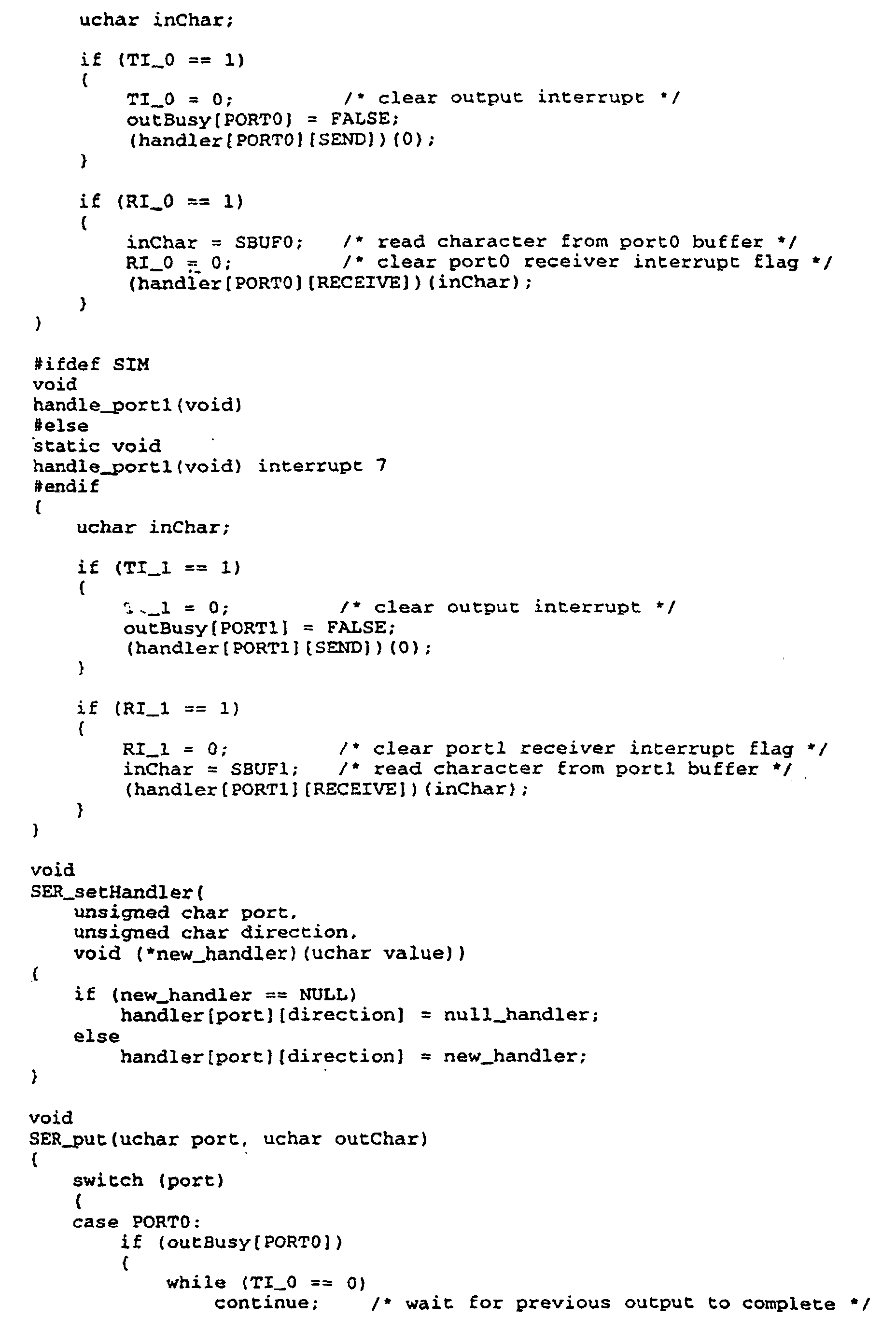
- SER setHandlerAssociates a callback routine with a particular port and event (SEND or RECEIVE). If the callback routine is NULL, then a do-nothing dummy callback routine is registered.
- SER enableInterrupt, SER disableInterruptEnable/disable interrupts on the indicated port These routines are used by the SECS communication control to shut down and restore communication with the robot during IMM-host conversations.
-
- The actual interrupt handlers, handle port0 and handle port1, do little more than reset the hardware and software flags associated with the port, and invoke the registered callback routine. Note the peculiar interface to the port1 handler: this is a result of working around a problem with the Franklin DS80C320 simulator handling of port1 interrupts. See the workaround discussion in the main exec routine for more detail.


- This module implements in software a general-purpose millisecond-level timer facility, which allows a client to register a routine to be run a designated number of milliseconds in the future. This is used to implement timers in the communication protocol, and to provide a safety net should the RF ID system fail to respond. It uses the built-in timer0.
- Timers are created by invoking MST create, passing it the delay in milliseconds and a pointer to the callback routine. The return value is a timerID, a value that may be passed to MST cancel to cancel the timer. The callback routine takes one argument, the timerID for which it was invoked, and should return no value. (Taking a second argument, such as a byte of user-defined data, was considered, but the IMM application did not have any use for it, and it would have increased the size of the timer data structure.)
- The basic data structure that the timer routines use simply contains ticksRemain, the number of ticks left until the timer expires, and the callback routine address. The timerID is an index into a statically allocated array of these structures. Every time the interrupt handler for timer0 is entered, the number of ticks remaining in each timer struct is checked, and when it drops to zero the callback routine is invoked. MST create just searches the array for an unused entry (if the ticksRemain is zero, the timer isn't being used), and MST cancel just sets ticksRemain to zero. The initialization routine, MST init, clears the array and starts up timer0.
- One limitation to the use of millisecond timers arises from the fact that the current implementation maintains a static array of NUM TIMERS timer data structures in the on-chip data area, so there is an upper limit on the number of simultaneously available timers. NUM_TIMERS is currently set to four.
- Another limitation arises from the fact that in the timer data structure the number of ticks left before expiration is maintained as a two-byte integer. Using a 10 ms. tick (27500 cycles of the 33.00 MHz crystal, counted every 12 cycles), this allows a maximum period of 655.36 sec. (about 10 min.) with a resolution of 10 ms.
- Note that in order to get a reasonably long tick we use timer0 in
mode 1, 16-bit mode, so we have to reload the count manually in the interrupt handler. This behavior is somewhat different from the way timer1 is used in auto-reload mode to clock the serial ports.


- This handler implements a simple watchdog timer, based on the DS80C320's hardware capabilities. It's purpose is to reset the micro-controller in case it get hung for some reason. "Getting hung" is inferred from a lack of change when change is expected. The timer is initialize by the executive during initialization, and reset periodically by the communication control finite state machines as external events move them through their sequence of state transitions. The timer will accumulate MAX TICKS ticks before resetting the CPU. The current values, MAX_TICKS = 128 and 2^26 clocks @ 33 MHz per tick, allow 4-5 minutes to pass without progress before the watchdog goes off.
- Note the use of the TIMED ACCESS macro to set the protected registers associated with the watchdog timer.


- The main routine in the program serves only to initialize the various modules, then enable interrupts and enter a do-nothing idle loop (though note the conditionally compiled workaround).
- The panic routine is a simple-minded way of stopping the IMM: it disables interrupts, sets an error code at the beginning external data memory, and spins. There might be something better to do -- add a display to the board to hold the error code? - but I can't think of anything. I have never seen this routine called in any phase of our testing. The error codes are defined in exec.h.
- There are a couple of conditional compilation parameters defined in the executive. Two of these, ASCII and SECS, control whether code for the ASCII or SECS interface is run during initialization. The other, SIM, controls the inclusion of code to work around the inability of the Franklin software to simulate
serial port 1 interrupts.


- This invention has been described and illustrated in connection with certain preferred embodiments which are illustrative of the principles of the invention. However, it should be understood that various modifications and changes may readily occur to those skilled in the art, and it is not intended to limit the invention to the construction and operation of the embodiment shown and described herein. Accordingly, additional modifications and equivalents may be considered as falling within the scope of the invention; the scope of the invention being defined by the claims hereinbelow.


Claims (7)
- An interface module (10) for use in a system for processing articles, which system includes a plurality of machine tools for processing articles, a pod for carrying the articles to be processed by said machine tools from one machine tool to another, a host processing controller (11) associated with said machine tools for controlling the operation thereof a robot (12) connected to each said machine tool for receiving said pod, opening said pod and for transporting the articles from within said pod into position on said machine tool for processing, and an identification system including an identification means (13) carried by the pod for identifying a particular pod and the articles carried therein, said interface module (10) being characterized by a single wire connection means between said identification system, said host controller (11) and said robot (12), said single wire connection means including a microprocessor (16) having means for identifying the source of a communication signal and for routing said communication signals between said identification system and said host controller (11) and between said host controller (11) and said robot (12) depending on its source.
- The interface module according to claim 1, characterized by further comprising a reader connected to said microprocessor (16) for reading said identification means (13) when said pod is placed on said machine tool.
- The interface module according to claim 2, characterized in that said identification means (13) has an RF transmitter and said reader comprises an RF receiver (21).
- The interface module according to claim 2, characterized in that said identification means (13) has an infrared transmitter and said reader comprises an infrared receiver (21).
- The interface module according to claim 2, characterized in that said identification means (13) is a barcode and said reader comprises an optical character reader.
- The interface module according to claim 2, characterized by further comprising detecting means mounted on said machine tool for detecting the presence of said pod, said detecting means connected with said host controller (11), whereby when said host controller (11) receives a message from said detecting means that a pod is in place for processing on said machine tool said host controller (11) will issue a command to said reader to identify said pod by reading its identification means (13).
- The interface module according to claim 6, characterized by further comprising a power source (15) and power regulation means for providing power to said microprocessor (16) and to said reader.
Applications Claiming Priority (5)
| Application Number | Priority Date | Filing Date | Title |
|---|---|---|---|
| US207957 | 1994-03-08 | ||
| US6903497P | 1997-12-12 | 1997-12-12 | |
| US69034P | 1997-12-12 | ||
| US09/207,957 US6418352B1 (en) | 1997-12-12 | 1998-12-09 | Integrated material management module |
| PCT/IB1998/002147 WO1999031713A2 (en) | 1997-12-12 | 1998-12-10 | Integrated material management module |
Publications (2)
| Publication Number | Publication Date |
|---|---|
| EP1040511A2 EP1040511A2 (en) | 2000-10-04 |
| EP1040511B1 true EP1040511B1 (en) | 2003-03-12 |
Family
ID=26749617
Family Applications (1)
| Application Number | Title | Priority Date | Filing Date |
|---|---|---|---|
| EP98965305A Expired - Lifetime EP1040511B1 (en) | 1997-12-12 | 1998-12-10 | Integrated material management module |
Country Status (6)
| Country | Link |
|---|---|
| US (1) | US6418352B1 (en) |
| EP (1) | EP1040511B1 (en) |
| JP (1) | JP4698833B2 (en) |
| KR (1) | KR20010033067A (en) |
| DE (1) | DE69812168T2 (en) |
| WO (1) | WO1999031713A2 (en) |
Families Citing this family (28)
| Publication number | Priority date | Publication date | Assignee | Title |
|---|---|---|---|---|
| DE19952194A1 (en) * | 1999-10-29 | 2001-05-17 | Infineon Technologies Ag | Plant for processing wafers |
| US7873428B2 (en) * | 2005-04-15 | 2011-01-18 | PEER Intellectual Property, Inc. | Automated job management |
| US7403984B2 (en) * | 2000-02-01 | 2008-07-22 | Asyst Technologies, Inc. | Automated tool management in a multi-protocol environment |
| US9785140B2 (en) * | 2000-02-01 | 2017-10-10 | Peer Intellectual Property Inc. | Multi-protocol multi-client equipment server |
| US8028049B1 (en) * | 2000-02-01 | 2011-09-27 | Peer Intellectual Property Inc. | Apparatus and method for web-based tool management |
| US6691068B1 (en) | 2000-08-22 | 2004-02-10 | Onwafer Technologies, Inc. | Methods and apparatus for obtaining data for process operation, optimization, monitoring, and control |
| EP1184724A1 (en) | 2000-08-29 | 2002-03-06 | Motorola, Inc. | Electronic device for a lithography mask container and method using the same |
| US6842655B1 (en) * | 2000-09-07 | 2005-01-11 | Donald W. Collins | Method and apparatus for processing an object |
| KR100640105B1 (en) * | 2001-04-19 | 2006-10-30 | 무라타 기카이 가부시키가이샤 | Automated guided vehicle, automated guided vehicle system and wafer conveyance method |
| US6879876B2 (en) | 2001-06-13 | 2005-04-12 | Advanced Technology Materials, Inc. | Liquid handling system with electronic information storage |
| US7756963B2 (en) * | 2001-07-05 | 2010-07-13 | PEER Intellectual Property, Inc. | Automated tool management in a multi-protocol environment |
| US20030063972A1 (en) * | 2001-10-02 | 2003-04-03 | Macronix International Co., Ltd. | Method for preventing miss-process in wafer transfer system |
| US7298275B2 (en) * | 2002-09-27 | 2007-11-20 | Rockwell Automation Technologies, Inc. | Machine associating method and apparatus |
| US7116993B2 (en) * | 2002-09-27 | 2006-10-03 | Rockwell Automation Technologies, Inc. | System and method for providing location based information |
| US7272456B2 (en) * | 2003-01-24 | 2007-09-18 | Rockwell Automation Technologies, Inc. | Position based machine control in an industrial automation environment |
| US7043316B2 (en) * | 2003-02-14 | 2006-05-09 | Rockwell Automation Technologies Inc. | Location based programming and data management in an automated environment |
| US20050071498A1 (en) * | 2003-09-30 | 2005-03-31 | Farchmin David W. | Wireless location based automated components |
| US20050070304A1 (en) * | 2003-09-30 | 2005-03-31 | Farchmin David W. | Distributed wireless positioning engine method and assembly |
| US7251535B2 (en) * | 2004-02-06 | 2007-07-31 | Rockwell Automation Technologies, Inc. | Location based diagnostics method and apparatus |
| US8645569B2 (en) * | 2004-03-12 | 2014-02-04 | Rockwell Automation Technologies, Inc. | Juxtaposition based machine addressing |
| US20050231372A1 (en) * | 2004-03-30 | 2005-10-20 | Tokyo Electron Limited | Device for remote identification of parts |
| US20050228528A1 (en) * | 2004-04-01 | 2005-10-13 | Farchmin David W | Location based material handling and processing |
| GB2436627B (en) * | 2006-03-29 | 2011-04-20 | Bridgeworks Ltd | Message handling |
| TWI598759B (en) * | 2006-07-10 | 2017-09-11 | 恩特葛瑞斯股份有限公司 | Material management system and method for supplying liquid stored in liquid storage vessels to substrate |
| EP2471627B1 (en) | 2010-12-29 | 2014-01-08 | W. Blösch AG | Method for producing mechanical workpieces from a board of monocrystalline silicon |
| KR101416958B1 (en) * | 2014-01-15 | 2014-07-09 | 손영전 | Reel managing system |
| US9792391B2 (en) | 2014-06-06 | 2017-10-17 | Siemens Product Lifecyle Management Software Inc. | Refining of material definitions for designed parts |
| US11580613B2 (en) * | 2019-06-28 | 2023-02-14 | Light Line Delivery Corp. | Parcel conveyance system |
Family Cites Families (13)
| Publication number | Priority date | Publication date | Assignee | Title |
|---|---|---|---|---|
| JPS61128512A (en) | 1984-11-28 | 1986-06-16 | Toshiba Corp | Control system in semiconductor substrate processing line |
| US5097421A (en) * | 1984-12-24 | 1992-03-17 | Asyst Technologies, Inc. | Intelligent waxer carrier |
| JPS63232921A (en) | 1987-03-19 | 1988-09-28 | Toshiba Corp | Manufacturing method and device |
| US4827110A (en) | 1987-06-11 | 1989-05-02 | Fluoroware, Inc. | Method and apparatus for monitoring the location of wafer disks |
| US5536128A (en) | 1988-10-21 | 1996-07-16 | Hitachi, Ltd. | Method and apparatus for carrying a variety of products |
| JP3212087B2 (en) * | 1988-10-21 | 2001-09-25 | 株式会社日立製作所 | Multi-product transfer method and device |
| DE59009700D1 (en) * | 1990-12-08 | 1995-10-26 | Itt Ind Gmbh Deutsche | Master-slave data transmission method with flexible single-wire bus. |
| JP3216205B2 (en) | 1992-03-27 | 2001-10-09 | 神鋼電機株式会社 | ID recognition device in semiconductor manufacturing system |
| DE4230913C2 (en) * | 1992-09-16 | 1994-09-15 | Itt Ind Gmbh Deutsche | Method and circuit arrangement for a serial bus system with a single-wire connection |
| US5387993A (en) * | 1993-06-25 | 1995-02-07 | Precision Tracking Fm, Inc. | Method for receiving and transmitting optical data and control information to and from remotely located receivers and transmitters in an optical locator system |
| US5701330A (en) * | 1994-12-16 | 1997-12-23 | Delco Electronics Corporation | Serial communication method and apparatus |
| US5742238A (en) * | 1995-09-01 | 1998-04-21 | Emtrak, Inc. | System for communication between a central controller and items in a factory using infrared light |
| JP3892493B2 (en) * | 1995-11-29 | 2007-03-14 | 大日本スクリーン製造株式会社 | Substrate processing system |
-
1998
- 1998-12-09 US US09/207,957 patent/US6418352B1/en not_active Expired - Lifetime
- 1998-12-10 JP JP2000539514A patent/JP4698833B2/en not_active Expired - Lifetime
- 1998-12-10 WO PCT/IB1998/002147 patent/WO1999031713A2/en active IP Right Grant
- 1998-12-10 DE DE69812168T patent/DE69812168T2/en not_active Expired - Fee Related
- 1998-12-10 EP EP98965305A patent/EP1040511B1/en not_active Expired - Lifetime
- 1998-12-10 KR KR1020007006428A patent/KR20010033067A/en active IP Right Grant
Also Published As
| Publication number | Publication date |
|---|---|
| JP2002509352A (en) | 2002-03-26 |
| JP4698833B2 (en) | 2011-06-08 |
| DE69812168T2 (en) | 2003-10-02 |
| WO1999031713A2 (en) | 1999-06-24 |
| US6418352B1 (en) | 2002-07-09 |
| KR20010033067A (en) | 2001-04-25 |
| WO1999031713A3 (en) | 1999-07-29 |
| EP1040511A2 (en) | 2000-10-04 |
| DE69812168D1 (en) | 2003-04-17 |
Similar Documents
| Publication | Publication Date | Title |
|---|---|---|
| EP1040511B1 (en) | Integrated material management module | |
| US6853876B2 (en) | Distributed control system architecture and method for a material transport system | |
| US5307346A (en) | Network-field interface for manufacturing systems | |
| US20060190118A1 (en) | Methods and apparatus for enhanced operation of substrate carrier handlers | |
| US7603195B2 (en) | Methods and apparatus for integrating large and small lot electronic device fabrication facilities | |
| US5778386A (en) | Global view storage management system for semiconductor manufacturing plants | |
| CN113335820A (en) | Warehousing and ex-warehouse method for directly butting stereoscopic warehouse and AGV | |
| US20050209721A1 (en) | Methods and apparatus for enhanced operation of substrate carrier handlers | |
| KR20050032996A (en) | Method and system for automating issue resolution in manufacturing execution and material control systems | |
| US7966090B2 (en) | Automated material handling system and method | |
| CN109786301A (en) | For automating the system and method for chip processing | |
| CN101273312B (en) | Methods and apparatus for enhanced operation of substrate carrier handlers | |
| US20070276531A1 (en) | Methods and apparatus for enhanced operation of substrate carrier handlers | |
| EP1569262A2 (en) | Methods and apparatus for enhanced operation of substrate carrier handlers | |
| US20230039788A1 (en) | Transport system and transport robot | |
| CN114955552A (en) | Control method for interaction between SMIF (Small input Signal Format) opener and automatic handling system and SMIF opener | |
| TW445418B (en) | Integrated material management module | |
| Marino et al. | Industrial LANs with real-time communication servers | |
| CN100423025C (en) | Management of byte transmission in a smartcard | |
| CN116980304A (en) | Automatic scene simulation system based on SECS/GEM communication method | |
| Huang et al. | Rapid setup of system control in a flexible automated production system | |
| KR20220123936A (en) | Method for program updating of passive device using automated guided vehicle in automated material handling system | |
| MAIMON | IMAC—An industrial material activity controller for electronic FMS | |
| Paidy et al. | Integration and Realtime Monitoring of Robotic Controllers | |
| Faucett et al. | A highly flexible automated odd-form component assembly cell |
Legal Events
| Date | Code | Title | Description |
|---|---|---|---|
| PUAI | Public reference made under article 153(3) epc to a published international application that has entered the european phase |
Free format text: ORIGINAL CODE: 0009012 |
|
| 17P | Request for examination filed |
Effective date: 20000703 |
|
| AK | Designated contracting states |
Kind code of ref document: A2 Designated state(s): CH DE FR GB LI NL |
|
| GRAG | Despatch of communication of intention to grant |
Free format text: ORIGINAL CODE: EPIDOS AGRA |
|
| 17Q | First examination report despatched |
Effective date: 20020403 |
|
| GRAG | Despatch of communication of intention to grant |
Free format text: ORIGINAL CODE: EPIDOS AGRA |
|
| GRAH | Despatch of communication of intention to grant a patent |
Free format text: ORIGINAL CODE: EPIDOS IGRA |
|
| GRAH | Despatch of communication of intention to grant a patent |
Free format text: ORIGINAL CODE: EPIDOS IGRA |
|
| GRAA | (expected) grant |
Free format text: ORIGINAL CODE: 0009210 |
|
| AK | Designated contracting states |
Designated state(s): CH DE FR GB LI NL |
|
| REG | Reference to a national code |
Ref country code: GB Ref legal event code: FG4D |
|
| REG | Reference to a national code |
Ref country code: CH Ref legal event code: NV Representative=s name: MICHELI & CIE INGENIEURS-CONSEILS Ref country code: CH Ref legal event code: EP |
|
| REF | Corresponds to: |
Ref document number: 69812168 Country of ref document: DE Date of ref document: 20030417 Kind code of ref document: P |
|
| ET | Fr: translation filed | ||
| PG25 | Lapsed in a contracting state [announced via postgrant information from national office to epo] |
Ref country code: GB Free format text: LAPSE BECAUSE OF NON-PAYMENT OF DUE FEES Effective date: 20031210 |
|
| PG25 | Lapsed in a contracting state [announced via postgrant information from national office to epo] |
Ref country code: LI Free format text: LAPSE BECAUSE OF NON-PAYMENT OF DUE FEES Effective date: 20031231 Ref country code: CH Free format text: LAPSE BECAUSE OF NON-PAYMENT OF DUE FEES Effective date: 20031231 |
|
| PLBE | No opposition filed within time limit |
Free format text: ORIGINAL CODE: 0009261 |
|
| STAA | Information on the status of an ep patent application or granted ep patent |
Free format text: STATUS: NO OPPOSITION FILED WITHIN TIME LIMIT |
|
| 26N | No opposition filed |
Effective date: 20031215 |
|
| PG25 | Lapsed in a contracting state [announced via postgrant information from national office to epo] |
Ref country code: NL Free format text: LAPSE BECAUSE OF NON-PAYMENT OF DUE FEES Effective date: 20040701 Ref country code: DE Free format text: LAPSE BECAUSE OF NON-PAYMENT OF DUE FEES Effective date: 20040701 |
|
| GBPC | Gb: european patent ceased through non-payment of renewal fee |
Effective date: 20031210 |
|
| REG | Reference to a national code |
Ref country code: CH Ref legal event code: PL |
|
| PG25 | Lapsed in a contracting state [announced via postgrant information from national office to epo] |
Ref country code: FR Free format text: LAPSE BECAUSE OF NON-PAYMENT OF DUE FEES Effective date: 20040831 |
|
| NLV4 | Nl: lapsed or anulled due to non-payment of the annual fee |
Effective date: 20040701 |
|
| REG | Reference to a national code |
Ref country code: FR Ref legal event code: ST |