EP1040039B1 - Adaptive absolute steering angle sensor - Google Patents
Adaptive absolute steering angle sensor Download PDFInfo
- Publication number
- EP1040039B1 EP1040039B1 EP98966577A EP98966577A EP1040039B1 EP 1040039 B1 EP1040039 B1 EP 1040039B1 EP 98966577 A EP98966577 A EP 98966577A EP 98966577 A EP98966577 A EP 98966577A EP 1040039 B1 EP1040039 B1 EP 1040039B1
- Authority
- EP
- European Patent Office
- Prior art keywords
- code
- angle sensor
- sensor according
- photodetector
- adaptive
- Prior art date
- Legal status (The legal status is an assumption and is not a legal conclusion. Google has not performed a legal analysis and makes no representation as to the accuracy of the status listed.)
- Expired - Lifetime
Links
- 230000003044 adaptive effect Effects 0.000 title claims description 31
- 230000003287 optical effect Effects 0.000 claims description 11
- 238000005259 measurement Methods 0.000 claims description 7
- 230000001360 synchronised effect Effects 0.000 claims description 4
- 238000013461 design Methods 0.000 claims description 3
- 238000003491 array Methods 0.000 claims 1
- 238000013507 mapping Methods 0.000 description 4
- 238000000034 method Methods 0.000 description 4
- 230000035945 sensitivity Effects 0.000 description 4
- 230000000694 effects Effects 0.000 description 3
- 230000007613 environmental effect Effects 0.000 description 3
- 238000011156 evaluation Methods 0.000 description 3
- 230000008901 benefit Effects 0.000 description 2
- 230000008859 change Effects 0.000 description 2
- 238000011109 contamination Methods 0.000 description 2
- 238000001514 detection method Methods 0.000 description 2
- 239000002245 particle Substances 0.000 description 2
- 229920003023 plastic Polymers 0.000 description 2
- 239000004033 plastic Substances 0.000 description 2
- 230000032683 aging Effects 0.000 description 1
- 230000000712 assembly Effects 0.000 description 1
- 238000000429 assembly Methods 0.000 description 1
- 230000004888 barrier function Effects 0.000 description 1
- 230000005540 biological transmission Effects 0.000 description 1
- 230000001427 coherent effect Effects 0.000 description 1
- 238000013211 curve analysis Methods 0.000 description 1
- 230000001419 dependent effect Effects 0.000 description 1
- 238000003745 diagnosis Methods 0.000 description 1
- 239000005337 ground glass Substances 0.000 description 1
- 238000003384 imaging method Methods 0.000 description 1
- 238000012806 monitoring device Methods 0.000 description 1
- 238000012544 monitoring process Methods 0.000 description 1
- 230000009467 reduction Effects 0.000 description 1
Images


Classifications
-
- G—PHYSICS
- G01—MEASURING; TESTING
- G01D—MEASURING NOT SPECIALLY ADAPTED FOR A SPECIFIC VARIABLE; ARRANGEMENTS FOR MEASURING TWO OR MORE VARIABLES NOT COVERED IN A SINGLE OTHER SUBCLASS; TARIFF METERING APPARATUS; MEASURING OR TESTING NOT OTHERWISE PROVIDED FOR
- G01D5/00—Mechanical means for transferring the output of a sensing member; Means for converting the output of a sensing member to another variable where the form or nature of the sensing member does not constrain the means for converting; Transducers not specially adapted for a specific variable
- G01D5/26—Mechanical means for transferring the output of a sensing member; Means for converting the output of a sensing member to another variable where the form or nature of the sensing member does not constrain the means for converting; Transducers not specially adapted for a specific variable characterised by optical transfer means, i.e. using infrared, visible, or ultraviolet light
- G01D5/32—Mechanical means for transferring the output of a sensing member; Means for converting the output of a sensing member to another variable where the form or nature of the sensing member does not constrain the means for converting; Transducers not specially adapted for a specific variable characterised by optical transfer means, i.e. using infrared, visible, or ultraviolet light with attenuation or whole or partial obturation of beams of light
- G01D5/34—Mechanical means for transferring the output of a sensing member; Means for converting the output of a sensing member to another variable where the form or nature of the sensing member does not constrain the means for converting; Transducers not specially adapted for a specific variable characterised by optical transfer means, i.e. using infrared, visible, or ultraviolet light with attenuation or whole or partial obturation of beams of light the beams of light being detected by photocells
- G01D5/347—Mechanical means for transferring the output of a sensing member; Means for converting the output of a sensing member to another variable where the form or nature of the sensing member does not constrain the means for converting; Transducers not specially adapted for a specific variable characterised by optical transfer means, i.e. using infrared, visible, or ultraviolet light with attenuation or whole or partial obturation of beams of light the beams of light being detected by photocells using displacement encoding scales
-
- B—PERFORMING OPERATIONS; TRANSPORTING
- B62—LAND VEHICLES FOR TRAVELLING OTHERWISE THAN ON RAILS
- B62D—MOTOR VEHICLES; TRAILERS
- B62D15/00—Steering not otherwise provided for
- B62D15/02—Steering position indicators ; Steering position determination; Steering aids
-
- G—PHYSICS
- G01—MEASURING; TESTING
- G01D—MEASURING NOT SPECIALLY ADAPTED FOR A SPECIFIC VARIABLE; ARRANGEMENTS FOR MEASURING TWO OR MORE VARIABLES NOT COVERED IN A SINGLE OTHER SUBCLASS; TARIFF METERING APPARATUS; MEASURING OR TESTING NOT OTHERWISE PROVIDED FOR
- G01D5/00—Mechanical means for transferring the output of a sensing member; Means for converting the output of a sensing member to another variable where the form or nature of the sensing member does not constrain the means for converting; Transducers not specially adapted for a specific variable
- G01D5/12—Mechanical means for transferring the output of a sensing member; Means for converting the output of a sensing member to another variable where the form or nature of the sensing member does not constrain the means for converting; Transducers not specially adapted for a specific variable using electric or magnetic means
- G01D5/244—Mechanical means for transferring the output of a sensing member; Means for converting the output of a sensing member to another variable where the form or nature of the sensing member does not constrain the means for converting; Transducers not specially adapted for a specific variable using electric or magnetic means influencing characteristics of pulses or pulse trains; generating pulses or pulse trains
- G01D5/249—Mechanical means for transferring the output of a sensing member; Means for converting the output of a sensing member to another variable where the form or nature of the sensing member does not constrain the means for converting; Transducers not specially adapted for a specific variable using electric or magnetic means influencing characteristics of pulses or pulse trains; generating pulses or pulse trains using pulse code
- G01D5/2492—Pulse stream
-
- G—PHYSICS
- G01—MEASURING; TESTING
- G01D—MEASURING NOT SPECIALLY ADAPTED FOR A SPECIFIC VARIABLE; ARRANGEMENTS FOR MEASURING TWO OR MORE VARIABLES NOT COVERED IN A SINGLE OTHER SUBCLASS; TARIFF METERING APPARATUS; MEASURING OR TESTING NOT OTHERWISE PROVIDED FOR
- G01D5/00—Mechanical means for transferring the output of a sensing member; Means for converting the output of a sensing member to another variable where the form or nature of the sensing member does not constrain the means for converting; Transducers not specially adapted for a specific variable
- G01D5/26—Mechanical means for transferring the output of a sensing member; Means for converting the output of a sensing member to another variable where the form or nature of the sensing member does not constrain the means for converting; Transducers not specially adapted for a specific variable characterised by optical transfer means, i.e. using infrared, visible, or ultraviolet light
- G01D5/32—Mechanical means for transferring the output of a sensing member; Means for converting the output of a sensing member to another variable where the form or nature of the sensing member does not constrain the means for converting; Transducers not specially adapted for a specific variable characterised by optical transfer means, i.e. using infrared, visible, or ultraviolet light with attenuation or whole or partial obturation of beams of light
- G01D5/34—Mechanical means for transferring the output of a sensing member; Means for converting the output of a sensing member to another variable where the form or nature of the sensing member does not constrain the means for converting; Transducers not specially adapted for a specific variable characterised by optical transfer means, i.e. using infrared, visible, or ultraviolet light with attenuation or whole or partial obturation of beams of light the beams of light being detected by photocells
- G01D5/347—Mechanical means for transferring the output of a sensing member; Means for converting the output of a sensing member to another variable where the form or nature of the sensing member does not constrain the means for converting; Transducers not specially adapted for a specific variable characterised by optical transfer means, i.e. using infrared, visible, or ultraviolet light with attenuation or whole or partial obturation of beams of light the beams of light being detected by photocells using displacement encoding scales
- G01D5/3473—Circular or rotary encoders
-
- G—PHYSICS
- G01—MEASURING; TESTING
- G01D—MEASURING NOT SPECIALLY ADAPTED FOR A SPECIFIC VARIABLE; ARRANGEMENTS FOR MEASURING TWO OR MORE VARIABLES NOT COVERED IN A SINGLE OTHER SUBCLASS; TARIFF METERING APPARATUS; MEASURING OR TESTING NOT OTHERWISE PROVIDED FOR
- G01D5/00—Mechanical means for transferring the output of a sensing member; Means for converting the output of a sensing member to another variable where the form or nature of the sensing member does not constrain the means for converting; Transducers not specially adapted for a specific variable
- G01D5/26—Mechanical means for transferring the output of a sensing member; Means for converting the output of a sensing member to another variable where the form or nature of the sensing member does not constrain the means for converting; Transducers not specially adapted for a specific variable characterised by optical transfer means, i.e. using infrared, visible, or ultraviolet light
- G01D5/32—Mechanical means for transferring the output of a sensing member; Means for converting the output of a sensing member to another variable where the form or nature of the sensing member does not constrain the means for converting; Transducers not specially adapted for a specific variable characterised by optical transfer means, i.e. using infrared, visible, or ultraviolet light with attenuation or whole or partial obturation of beams of light
- G01D5/34—Mechanical means for transferring the output of a sensing member; Means for converting the output of a sensing member to another variable where the form or nature of the sensing member does not constrain the means for converting; Transducers not specially adapted for a specific variable characterised by optical transfer means, i.e. using infrared, visible, or ultraviolet light with attenuation or whole or partial obturation of beams of light the beams of light being detected by photocells
- G01D5/347—Mechanical means for transferring the output of a sensing member; Means for converting the output of a sensing member to another variable where the form or nature of the sensing member does not constrain the means for converting; Transducers not specially adapted for a specific variable characterised by optical transfer means, i.e. using infrared, visible, or ultraviolet light with attenuation or whole or partial obturation of beams of light the beams of light being detected by photocells using displacement encoding scales
- G01D5/34776—Absolute encoders with analogue or digital scales
Definitions
- the invention relates to an adaptive absolute steering angle sensor for absolute determination of an angle of rotation, in particular to determine the steering angle in a motor vehicle by means of an attached over an angular range of 360 ° Codes for determining the angle, the code and a detector arrangement rotatably arranged relative to one another are, with an absolute angle determination by Reading the contrast information using a microprocessor done, which is both the angular position of the code as well the fine resolution of the angles by the relative position of the recognized codes for imaging on the photodetector arrangement determined and at the same time the overall function for each measurement of the system is checked and adjusted.
- WO-A-9325865 is a device for absolute determination the position of a linearly displaceable component known.
- this device are the code and a detector arrangement slidable relative to each other.
- This Device is also for absolute determination of an angle of rotation suitable, then a code and a detector arrangement are arranged rotatable relative to each other.
- the invention has for its object the determination the absolute angular position of a rotor, in particular the Steering wheel of a motor vehicle to further improve.
- the code is used on a single Detected and installed location of the photodetector used for angle determination. Furthermore, a coherent Segment of the code track on at least one photo detector line mapped, wherein at least one code word is detected , which corresponds to a predetermined angle, and the location of the code word is relative to the fixed position of the photodetector line measured. Furthermore, the code is over a Optics mapped onto the photodetector line so that with a reading cycle of the line, both the absolute angle information determined as well as the overall function of the system checked and adjusted. To monitor system functions will have at least one reference silhouette on the photodetector line projected.
- the code is chosen so that it covers the entire Scope in the viewing area of the photodetector arrangement not repeated.
- the code is single-track, clear and closed.
- the sensor has the advantage that over known methods the angular resolution does not differ from the resolution the code of the code track and not the number of Codewords only from the resolution of the sensors of the photodetector arrangement depends, i.e. that the angular resolution is independent of the code. Without using the reference mark the angular resolution depends on the number of code words from. If at least one code word of the code track from the photodetector arrangement would be recorded, one would have with 360 code words an angular resolution of one degree.
- the angular resolution does not depend on the number of code words depends on, as few code words as possible should be used, the sensor sensitivity to environmental influences, such as. Pollution, decrease. That will e.g. by using 6-bit or 7-bit codes instead reached by 8-bit codes.
- the measurement is carried out in software in a microcontroller made the image data of the photodetector arrangement used.
- At least two different images of one or more scope codes are mapped onto the photodetector arrangement.
- the code track can be illuminated with parallel light or be illuminated from one side.
- the reference silhouettes can be created by a corresponding Software both cyclically and by individual Switch on a computer-controlled monitoring device be generated.
- the angular range is within 0 ° to 360 ° over the driving speed of the vehicle determined.
- To capture the absolute steering angle even when vehicle systems are switched off the steering angle is activated by briefly switching on the steering angle sensor at time intervals when there is no rotation preferably greater than 180 ° is determined.
- an adaptive absolute angle sensor is still at least one light source for illuminating an angular range of the code is provided, and it is a photodetector arrangement for the detection of the illuminated angular range of the code provided, the light source and a microcontroller is assigned to the photo detector arrangement is.
- a first embodiment there are two as the light source light emitting diodes symmetrical to the optical axis arranged, this together with the photodetector arrangement and optics on the same side of the annulus are provided.
- one is in bright places of the code translucent circular coding ring intended. Furthermore, at least one is light-emitting Diode on one side of the coding ring and the photodetector arrangement arranged on the other side of the coding ring. An optic is preferably on the side of the light-emitting diode provided.
- the photodetector arrangement has two sensors has, with respect to the course of the code track their synchronous viewing arranged vertically one above the other are and that the images of both sensors together be compared.
- the two pictures can local pollution particles (code, optics) as well Sensor errors are recognized.
- Two can be used as sensors Line sensors or two superimposed sections an area sensor may be provided.
- two sensors are used synchronous registration of neighboring code words of the code track arranged horizontally next to each other.
- Charge-coupled are preferably used as photodetectors Elements (CCD) are provided.
- the light-dark lines of the code words should be used for further Reduction of sensor sensitivity to environmental influences have the largest possible dimensions.
- the light-dark lines of the code words have a width of 2 to 3 mm.
- a matt screen is arranged, and that the optics and the photodetector arrangement on the other side of the coding ring are provided.
- the Coding ring has a prismatic cross section, wherein a light source radiating in the axial direction of the coding ring is arranged.
- a transparent Coding ring sectionally adjacent cylinders or lenses for generating the code and mapping the Light sources arranged on the photodetector arrangement, the cylinders being in the axial direction of the coding ring extend and with an end face on the coding ring are attached and assigned to the light sources and with their other, exposed end faces of the photodetector assembly assigned.
- the exposed faces of the cylinders are expediently flat or lenticular.
- two are punctiform Light sources next to each other at a constant distance and a single photodetector arrangement is provided. This Arrangement has the advantage that despite the change in radial distance of the coding ring by radial impact the steering wheel or despite changing the distance of the components among themselves through mechanical or thermal influences due to the different shadowing of the two light sources, the distance between which remains constant, the Position and angular position of the code on the photodetector arrangement can be precisely detected.
- the same advantageous effect can be achieved be that a point light source and two in different distance from the light source one above the other arranged photodetector lines are provided.
- the angle determining Code on the coding ring at least one reference code assigned.
- the reference code can be next to the angle-determining code, or above and provided below the angle-determining code his.
- a digital, single-track code 2 appropriate.
- the code is designed so that it can over not the entire scope in one area of consideration 3 repeated. It can be single-track, clear and closed be designated. For the determination of the absolute Steering angle within 360 ° is enough for this single track Code.
- the viewing area 3 is characterized by light emitting Diodes 4 and 5 illuminated and an optics 6 on a Photo detector line 7 shown. This line of photo detectors is designed as a charge-coupled detector line (CCD line).
- the code 2 in the viewing area 3 is according to FIG. 1a executed as a black and white code.
- the code is called the contrast difference from the photodetector line to a microcontroller 8 given. This evaluates the contrast differences decodes it and returns the rotation angle position via an interface 9 to the vehicle 10.
- the entire unit is powered by a power supply 12 the 12 volt vehicle network 13 supplied.
- This method is used to record the angular position a contiguous segment of the code track, namely the Viewing area 3, mapped onto the photodetector line 7.
- the absolute steering angle can be within 0 to 360 ° clearly with a resolution depending on the selected code be determined.
- the viewing area is chosen so that at least one code word 29 (Fig. 2) of the code track of the CCD line 7 is detected.
- Each code word corresponds a steering angle, the angular resolution depending on the number depends on the code words. With 360 code words you have one One degree resolution. In this way, the rough angle certainly.
- the position or the distance of the code word to the reference mark and thus the angular resolution of the steering angle sensor is therefore only dependent on the resolution with which the photodetector line resolves the viewing area.
- the photodetector line has 128 pixels, with which steering angle resolutions of ⁇ 0.2 0 can be achieved.
- the absolute angle is thus composed of the code word and the position of the code word in relation to the photo detector line.
- the resolution of the steering angle sensor on the condition that the viewing area 3 has at least one code word only depends on the resolution of the photodetector line
- the light / dark lines of the code word can be large Have dimensions, e.g. 2 - 3 mm. It is useful to have one Use code with as few code words as possible. The e.g. through the use of 6 bit or 7 bit codes instead of e.g. 8 bit codes reached. This will make the Sensor sensitivity to environmental influences, e.g. Pollution, reduced.
- the steering angle sensor can be used to further increase the sensitivity further developed according to Figures 4 and 4a become.
- the code on a scope 41 is in an upper one rough area 42 to detect the 0 to 360 ° and in divided a lower fine region 43.
- On the photo detector line 7 is used to determine the rough angle a light emitting diode 45 illuminated rough code area 42 mapped via an optic 47.
- the fine code area 43 by means of a light emitting Diode 46 illuminated and a smaller section over one Optics 48 mapped onto the photodetector line 7.
- This smaller section can in turn contain a code, that covers +/- 10 °. Both optics are through an aperture 44 Cut. By depicting a smaller section can increase the resolution and accuracy accordingly become.
- FIG. 3 Another embodiment of the steering angle sensor is in Fig. 3 shown.
- the arrangement corresponds to that of FIG. 1, however, a monitoring and interface microprocessor 11 provided in a software is installed, either when switching on and / or cyclically one or more light-emitting Turns on diodes 32 and 33 via a mask 34 be mapped onto the photodetector line 7.
- a monitoring and interface microprocessor 11 provided in a software is installed, either when switching on and / or cyclically one or more light-emitting Turns on diodes 32 and 33 via a mask 34 be mapped onto the photodetector line 7.
- By sequential Turning on diodes 32 and 33 will be on the photodetector line one or more silhouettes in succession Creates silhouettes.
- This allows the function of the overall arrangement checked over all components. at Soiling in the area of the optical components can then e.g. the light output of the light-emitting diodes 4 and 5 easily by increasing the control current accordingly be adjusted. Even the
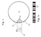
- FIG. 1 While in Fig. 1 an embodiment of the steering angle sensor is shown who works with incident light, 5 shows a sensor that works with transmitted light.
- a circular ring 54 in the area of the light lines a code 53 translucent.
- a light emitting diode 52 Inside the ring is a light emitting diode 52 and an optics 55 arranged. Both are outside the annulus Associated with photodetector line 51.
- the code 53 according to FIG. 5a corresponds to the code of FIG. 1a.
- the code track is in in this case illuminated with parallel light.
- Line sensors 65 and 66 can also be an area sensor 61 can be used for this function.
- FIG. 7a is a code 73 with two tracks 71, 72, as shown in FIG. 7a can be seen.
- Each of the two code tracks is with a line sensor 65, 66 or different lines of an area sensor 61 considered.
- the code of the second code track can now e.g. inverse to that of the first code track be so that by simply subtracting the measured values in the microcontroller 8 a simple control of the sensor input results.
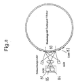
- FIG. 8 Another arrangement is shown in FIG. 8. to Increasing the sensor security is in this embodiment a second CCD sensor 85 horizontally next to the first CCD sensor 84 placed. Due to the horizontal arrangement are different code words at two different Set the code track 82 registered. The difference in Measurement results of both CCD sensors must be the differential viewing angle result of both photo detectors to the code track. This angle is due to the position of the CCD sensors known.
- a corresponding one can also be used larger linear CCD sensor can be used. Furthermore is the combination of two photo detector lines in an integrated circuit 81 with a common one Housing possible.
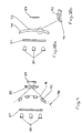
- one or more LEDs 86 directly or via a focusing screen 87 via a Optics 88 mapped onto a photodetector arrangement 89.
- the Coding consists of a ring 90, the translucent Angular ranges 91 and opaque angular ranges 92 through injected recesses or through accordingly translucent and opaque plastics be generated.
- a or several LEDs 86 directly or via the focusing screen 87 or Fresnel lens by means of an arrangement of the same type or differently designed cylindrical lenses 93 without further optics shown on the photodetector array 89.
- the cylinder lenses 93 produce stripes of different sizes Brightness on the photodetector array 89.
- a corresponding code is generated which is used for Scanning the steering angle is used.
- the arrangement of the cylindrical lenses is shown in Figure 10b.
- a coding ring 95 can be designed in this way be that he's out of a prismatic arrangement there is one or more LEDs 86 e.g. axially the Irradiate the arrangement (Fig. 11). The redirection of the light rays happens at the hypotenuse 95a of the prism.
- the radial light emission at the circumference of the coding ring 95 is so designed that there are quasi-flat surface areas 96 and Cylinder lens assemblies 93 are located.
- Through the plan A homogeneous light emission on the radial surface is created attached photodetector assembly 89. Through the cylindrical lenses 93 areas are created on the photodetector arrangement 89 low and high luminance.
- the coding for determining the steering angle is done by appropriate distribution of quasi plan areas and by the same or different designed cylindrical lenses.
- s 86 in a transparent Coding ring 97 radiated and this coding ring has a number of cylinders 98 on one end directly are connected to the coding ring and at the other end are either flat or lenticular. So that will a corresponding luminance on each of these cylinders occur, which is detected via the photodetector arrangement 89 can be. Through areas with and without cylinders and design a code can be applied to the density and accordingly can be detected.
- the arrangements can be designed in radial or axial form the direction of light passage in two possible directions can be selected.
- FIG. 13 there is no lens arrangement required.
- An almost point light source e.g. by using a laser diode 101 with a light emitting Area of e.g. 2 ⁇ x 3 ⁇ with the barrier layer e.g. parallel to the axis illuminates the coding ring 90, the from the translucent areas 91 and the opaque Areas 92 exists.
- Behind the coding ring 90 a linear photodetector arrangement 89 is provided, on which there is a luminance distribution in the translucent areas arises from the coding. This luminance distribution is evaluated.
- the arrangement according to Fig. 13 can by the application of two side by side, at a known distance Laser diodes 101 and 102 are improved, as shown in Fig. 14a and b.
- the evaluation is the same as for the embodiment of FIG. 13 described. Changes however, the radial distance of the coding ring 90 by radial Impact of the steering wheel or changes due to mechanical or thermal influences the distance of the components with each other, which is shown in FIG. 14a by items 1 and 2 the photodetector arrangement is indicated, so can by different shadowing of the two laser diodes 101 and 102, the distance of which remains constant, on the photodetector array 89 nevertheless the position and angular position of the code be accurately detected.
- the laser diodes 101 and 102 are excited in quick succession, with the Time is selected as short, e.g. 10 ⁇ s - 100 ⁇ s that in no change in angle restricting accuracy at this time occurs on the steering wheel.
- the Time is selected as short, e.g. 10 ⁇ s - 100 ⁇ s that in no change in angle restricting accuracy at this time occurs on the steering wheel.
- a monolithic LED in double or triple arrangement can be used for light-emitting surfaces with very small expansion in the axial direction appropriate masks are generated.
- FIG. 16 shows a combination an angle-determining code 105 with a reference code 106.
- the angle can be evaluated as well as via checked the reference code on the one hand the CCD or the photodecoder arrangement be, on the other hand about the known Distances of the reference code the distance and the exact Angles can be determined.
- the angle-determining code 105 can also be parallel to Reference code 106 can be applied as shown in FIG. 17 is shown. If the reference code 106, as shown here, applied at the top and bottom of the edge of the angle codes, so an axial tolerance affects the image the reference code 106.
- Both codes can be mapped together and by means of LEDs 86 are illuminated, as can be seen from FIG. 18.
- An angle signal can thus be sent to the photodetector arrangement 89 107 and reference signal 108 corresponding to FIG. 19 generated and evaluated.
Description
Die Erfindung betrifft einen adaptiven absoluten Lenkwinkelsensor zur Absolutbestimmung eines Drehwinkels, insbesondere zur Ermittlung des Lenkwinkels in einem Kraftfahrzeug mittels eines über einen Winkelbereich von 360° angebrachten Codes für die Ermittlung des Winkels, wobei der Code und eine Detektoranordnung relativ zueinander drehbar angeordnet sind, wobei eine absolute Winkelbestimmung durch Auslesen der Kontrastinformation mittels eines Mikroprozessors erfolgt, der sowohl die Winkellage des Codes als auch die Feinauflösung der Winkel durch die relative Lage des erkannten Codes zur Abbildung auf der Fotodetektoranordnung ermittelt und wobei zugleich bei jeder Messung die Gesamtfunktion des Systems überprüft und angepaßt wird.The invention relates to an adaptive absolute steering angle sensor for absolute determination of an angle of rotation, in particular to determine the steering angle in a motor vehicle by means of an attached over an angular range of 360 ° Codes for determining the angle, the code and a detector arrangement rotatably arranged relative to one another are, with an absolute angle determination by Reading the contrast information using a microprocessor done, which is both the angular position of the code as well the fine resolution of the angles by the relative position of the recognized codes for imaging on the photodetector arrangement determined and at the same time the overall function for each measurement of the system is checked and adjusted.
Aus der EP-A-0 377 097 ist ein Lenkwinkelsensor für ein Kraftfahrzeug bekannt, bei dem auf einem Ring ein einspuriger Streifencode vorgesehen ist, dem mehrere Sensoren zugeordnet sind.From EP-A-0 377 097 a steering angle sensor for a Motor vehicle known in which a single track on a ring Stripe code is provided, the multiple sensors assigned.
Aus der WO-A-9325865 ist eine Vorrichtung zur Absolutbestimmung der Position eines linear verschiebbaren Bauteils bekannt. Bei dieser Vorrichtung sind der Code und eine Detektoranordnung relativ zueinander verschiebbar. Diese Vorrichtung ist auch zur Absolutbestimmung eines Drehwinkels geeignet, wobei dann ein Code und eine Detektoranordnung relativ zueinander drehbar angeordnet sind. From WO-A-9325865 is a device for absolute determination the position of a linearly displaceable component known. In this device are the code and a detector arrangement slidable relative to each other. This Device is also for absolute determination of an angle of rotation suitable, then a code and a detector arrangement are arranged rotatable relative to each other.
Der Erfindung liegt die Aufgabe zugrunde, die Bestimmung der absoluten Winkelstellung eines Rotors, insbesondere des Lenkrades eines Kraftfahrzeuges, weiter zu verbessern.The invention has for its object the determination the absolute angular position of a rotor, in particular the Steering wheel of a motor vehicle to further improve.
Erfindungsgemäß wird der Code mittels einer an einer einzigen Stelle angebrachten Fotodetektoranordnung ermittelt und zur Winkelbestimmung verwendet. Weiterhin wird ein zusammenhängendes Segment der Codespur auf mindestens eine Fotodektorzeile abgebildet, wobei mindestens ein Codewort erfaßt wird, dem ein vorbestimmter Winkel entspricht, und die Lage des Codewortes wird bezüglich der festen Position der Fotodetektorzeile vermessen. Weiterhin wird der Code über eine Optik so auf die Fotodetektorzeile abgebildet, daß mit einem Auslesezyklus der Zeile sowohl die absolute Winkelinformation ermittelt als auch die Gesamtfunktion des Systems überprüft und angepaßt wird. Zur Überwachung der Systemfunktionen wird mindestens ein Referenzschattenbild auf die Fotodetektorzeile projiziert.According to the invention, the code is used on a single Detected and installed location of the photodetector used for angle determination. Furthermore, a coherent Segment of the code track on at least one photo detector line mapped, wherein at least one code word is detected , which corresponds to a predetermined angle, and the location of the code word is relative to the fixed position of the photodetector line measured. Furthermore, the code is over a Optics mapped onto the photodetector line so that with a reading cycle of the line, both the absolute angle information determined as well as the overall function of the system checked and adjusted. To monitor system functions will have at least one reference silhouette on the photodetector line projected.
Der Code ist so gewählt, daß er sich über den gesamten Umfang im Betrachtungsbereich der Fotodetektoranordnung nicht wiederholt. Der Code ist einspurig, eindeutig und geschlossen. Der Sensor weist den Vorteil auf, daß gegenüber bekannten Verfahren die Winkelauflösung nicht von der Auflösung des Codes der Codespur und nicht von der Anzahl der Codeworte sondern nur von der Auflösung der Sensoren der Fotodetektoranordnung abhängt, d.h., daß die Winkelauflösung unabhängig vom Code ist. Ohne die Verwendung der Referenzmarke hängt die Winkelauflösung von der Anzahl der Codeworte ab. Wenn mindestens ein Codewort der Codespur von der Fotodetektoranordnung erfaßt wird, hätte man bei 360 Codeworten eine Winkelauflösung von einem Grad.The code is chosen so that it covers the entire Scope in the viewing area of the photodetector arrangement not repeated. The code is single-track, clear and closed. The sensor has the advantage that over known methods the angular resolution does not differ from the resolution the code of the code track and not the number of Codewords only from the resolution of the sensors of the photodetector arrangement depends, i.e. that the angular resolution is independent of the code. Without using the reference mark the angular resolution depends on the number of code words from. If at least one code word of the code track from the photodetector arrangement would be recorded, one would have with 360 code words an angular resolution of one degree.
Da die Winkelauflösung nicht von der Anzahl der Codeworte abhängt, sollten möglichst wenige Codeworte verwendet werden, um die Sensorempfindlichkeit gegenüber Umwelteinflüssen, wie z.B. Verschmutzung, zu verringern. Das wird z.B durch die Verwendung von 6-Bit- oder 7-Bit-Codes anstelle von 8-Bit-Codes erreicht.Because the angular resolution does not depend on the number of code words depends on, as few code words as possible should be used, the sensor sensitivity to environmental influences, such as. Pollution, decrease. That will e.g. by using 6-bit or 7-bit codes instead reached by 8-bit codes.
Das Vermessen wird softwaremäßig in einem Mikrocontroller vorgenommen, der hierzu die Bilddaten der Fotodetektoranordnung verwendet.The measurement is carried out in software in a microcontroller made the image data of the photodetector arrangement used.
Zur weiteren Erhöhung der Auflösung können mindestens zwei unterschiedliche Abbildungen eines oder mehrerer Umfangscodes auf die Fotodetektoranordnung abgebildet werden.To further increase the resolution, at least two different images of one or more scope codes are mapped onto the photodetector arrangement.
Die Codespur kann mit parallelem Licht durchleuchtet oder von einer Seite beleuchtet werden.The code track can be illuminated with parallel light or be illuminated from one side.
Bei Verschmutzungen im Bereich optischer Komponenten kann dann z.B. die Leistung der Lichtquellen durch Erhöhung des Steuerstromes leicht angepaßt werden. Auch der Ausfall von einzelnen Detektoren der Fotodetektoranordnung wird bemerkt und kann durch rechnerische Maßnahmen ausgeglichen werden. Die Referenzschattenbilder können durch eine entsprechende Software sowohl zyklisch als auch durch individuelles Einschalten einer rechnergesteuerten Überwachungseinrichtung erzeugt werden.With contamination in the area of optical components can then e.g. the performance of the light sources by increasing the Control current can be easily adjusted. Even the failure of individual detectors of the photodetector arrangement are noticed and can be compensated by arithmetic measures become. The reference silhouettes can be created by a corresponding Software both cyclically and by individual Switch on a computer-controlled monitoring device be generated.
Weiterhin ist es möglich, daß für den Ausgleich optischer und mechanischer Toleranzen die Flankensteilheit und Abbildungsgröße der auf der Detektorzeile abgebildeten Signale ausgewertet werden.Furthermore, it is possible for optical compensation and mechanical tolerances the slope and image size of the signals shown on the detector line be evaluated.
Der Winkelbereich wird innerhalb 0° bis 360° über die Fahrgeschwindigkeit des Fahzeugs ermittelt. Zur Erfassung des absoluten Lenkwinkels auch bei abgeschalteten Fahrzeugsystemen wird der Lenkwinkel durch kurzes Einschalten des Lenkwinkelsensors in Zeitintervallen, in denen keine Drehung vorzugsweise größer 180° möglich ist, ermittelt.The angular range is within 0 ° to 360 ° over the driving speed of the vehicle determined. To capture the absolute steering angle even when vehicle systems are switched off the steering angle is activated by briefly switching on the steering angle sensor at time intervals when there is no rotation preferably greater than 180 ° is determined.
Dadurch, daß mit einer einzigen Fotodetektoranordnung der Winkel im Bereich von 360° sehr schnell ausgewertet werden kann, ist das System durch einfaches Mitregistrieren der 360° Überschreitung und damit für mehrere Umdrehungen geeignet. Um das nicht nur für den Fahrbetrieb zu gewährleisten, muß das System im Standbybetrieb jeweils kurzzeitig eingeschaltet werden, wobei die Einschaltintervalle so gewählt werden, daß in diesem Intervall keine Lenkraddrehung größer 360° möglich ist. Da das System zur Datenübertragung eine Schnittstelle zum Fahrzeugrechner hat, kann von dort aus die Fahrzeuggeschwindigkeit übernommen werden, um den Nullbereich des Lenkwinkels zu definieren, denn ab einer bestimmten Geschwindigkeit ist bei normalen Fahrzeugen kein Lenkwinkel über z.B. +/-90° von der Nullstellung aus fahrbar. The fact that with a single photodetector Angles in the range of 360 ° can be evaluated very quickly can, the system is simply by registering the 360 ° crossing and therefore for several revolutions suitable. In order not only to ensure this for driving operations, the system must be briefly in standby mode be switched on, the switch-on intervals so be selected that no steering wheel rotation in this interval greater than 360 ° is possible. Because the system for data transmission has an interface to the vehicle computer from there the vehicle speed is taken over, to define the zero range of the steering angle, because from is a certain speed in normal vehicles no steering angle above e.g. +/- 90 ° from the zero position off mobile.
Bei einem adaptiven absoluten Winkelsensor ist weiterhin mindestens eine Lichtquelle für die Beleuchtung eines Winkelbereichs des Codes vorgesehen, und es ist eine Fotodetektoranordnung für die Erfassung des beleuchteten Winkelbereichs des Codes vorgesehen, wobei der Lichtquelle und der Fotodektektoranordnung ein Mikrocontroller zugeordnet ist.With an adaptive absolute angle sensor is still at least one light source for illuminating an angular range of the code is provided, and it is a photodetector arrangement for the detection of the illuminated angular range of the code provided, the light source and a microcontroller is assigned to the photo detector arrangement is.
In einer ersten Ausführungsform sind als Lichtquelle zwei lichtemittierende Dioden symmetrisch zur optischen Achse angeordnet, wobei diese zusammen mit der Fotodetektoranordnung und einer Optik auf derselben Seite des Kreisringes vorgesehen sind.In a first embodiment there are two as the light source light emitting diodes symmetrical to the optical axis arranged, this together with the photodetector arrangement and optics on the same side of the annulus are provided.
In einer zweiten Ausführungsform ist ein an hellen Stellen des Codes lichtdurchlässiger kreisförmiger Codierring vorgesehen. Weiterhin sind mindestens eine lichtemittierende Diode auf einer Seite des Codierringes und die Fotodetektoranordnung auf der anderen Seite des Codierringes angeordnet. Eine Optik ist- vorzugsweise auf der Seite der lichtemittierenden Diode vorgesehen.In a second embodiment, one is in bright places of the code translucent circular coding ring intended. Furthermore, at least one is light-emitting Diode on one side of the coding ring and the photodetector arrangement arranged on the other side of the coding ring. An optic is preferably on the side of the light-emitting diode provided.
Zur Erhöhung der Sicherheit des Winkelsensors und zur Erfassung von Codefehlern ist in einer weiteren Ausgestaltung vorgesehen, daß die Fotodetektoranordnung zwei Sensoren aufweist, die bezüglich des Verlaufs der Codespur zu deren synchronen Betrachtung vertikal übereinander angeordnet sind und daß die Bilder beider Sensoren miteinander verglichen werden. Durch den Vergleich der beiden Bilder können lokale Verschmutzungspartikel (Code, Optik) sowie Sensorfehler erkannt werden. Als Sensoren können zwei Zeilensensoren oder zwei übereinanderliegende Abschnitte eines Flächensensors vorgesehen sein.To increase the security of the angle sensor and Detection of code errors is in a further embodiment provided that the photodetector arrangement has two sensors has, with respect to the course of the code track their synchronous viewing arranged vertically one above the other are and that the images of both sensors together be compared. By comparing the two pictures can local pollution particles (code, optics) as well Sensor errors are recognized. Two can be used as sensors Line sensors or two superimposed sections an area sensor may be provided.
In einer weiteren Ausgestaltung sind zwei Sensoren zur synchronen Registrierung benachbarter Codeworte der Codespur horizontal nebeneinander angeordnet. In a further embodiment, two sensors are used synchronous registration of neighboring code words of the code track arranged horizontally next to each other.
Als Fotodetektoren sind vorzugsweise ladungsgekoppelte Elemente (CCD) vorgesehen.Charge-coupled are preferably used as photodetectors Elements (CCD) are provided.
Die Hell-Dunkel-Linien der Codeworte sollten zur weiteren Verringerung der Sensorempfindlichkeit gegenüber Umwelteinflüssen möglichst großen Abmessungen haben. Vorzugsweise weisen die Hell-Dunkel-Linien der Codeworte eine Breite von 2 bis 3 mm auf.The light-dark lines of the code words should be used for further Reduction of sensor sensitivity to environmental influences have the largest possible dimensions. Preferably the light-dark lines of the code words have a width of 2 to 3 mm.
In einer Ausführungsform ist vorgesehen, daß zwischen Lichtquelle und dem transparenten Codierring eine Mattscheibe angeordnet ist, und daß die Optik und die Fotodetektoranordnung auf der anderen Seite des Codierringes vorgesehen sind.In one embodiment it is provided that between Light source and the transparent coding ring a matt screen is arranged, and that the optics and the photodetector arrangement on the other side of the coding ring are provided.
In einer weiteren Ausführungsform weist ein transparenter Codierring abschnittsweise nebeneinander liegende Zylinderlinsen zur Erzeugung des Codes und Abbildung der Lichtquellen auf der Fotodetektoranordnung auf. Bei dieser Ausführungsform wird eine zusätzliche Optik eingespart. Durch die Zylinderlinsen entstehen Streifen unterschiedlicher Helligkeit auf dem Fotodetektorarray.In a further embodiment, a transparent one Coding ring sections of cylindrical lenses lying side by side for generating the code and mapping the light sources on the photodetector array. In this embodiment an additional look is saved. Through the Cylindrical lenses create stripes of different brightness on the photo detector array.
In einer weiteren Ausgestaltung ist vorgesehen, daß der Codierring einen prismatischen Querschnitt aufweist, wobei eine in axialer Richtung des Codierringes strahlende Lichtquelle angeordnet ist.In a further embodiment it is provided that the Coding ring has a prismatic cross section, wherein a light source radiating in the axial direction of the coding ring is arranged.
In einer weiteren Ausführungsform sind auf einem transparenten Codierring abschnittsweise nebeneinanderliegende Zylinder oder Linsen zur Erzeugung des Codes und Abbildung der Lichtquellen auf der Fotodetektoranorndung angeordnet, wobei sich die Zylinder in axialer Richtung des Codierringes erstrecken und mit einer Stirnfläche auf dem Codierring befestigt sind und den Lichtquellen zugeordnet sind und mit ihrer anderen, freiliegenden Stirnflächen der Fotodetektoranordnung zugeordnet sind. Durch Bereiche mit und ohne Zylinder und Gestaltung der Dichte bzw. mit und ohne Linsen kann ein Code aufgebracht und entsprechend detektiert werden. Die freiliegenden Stirnflächen der Zylinder sind zweckmäßig plan oder linsenförmig ausgebildet.In a further embodiment are on a transparent Coding ring sectionally adjacent cylinders or lenses for generating the code and mapping the Light sources arranged on the photodetector arrangement, the cylinders being in the axial direction of the coding ring extend and with an end face on the coding ring are attached and assigned to the light sources and with their other, exposed end faces of the photodetector assembly assigned. Through areas with and without cylinder and density design or with and without A code can be applied to lenses and detected accordingly become. The exposed faces of the cylinders are expediently flat or lenticular.
In einer Ausführungsform ist dem transparenten Codierring, der lichtdurchlässige Bereiche und lichtundurchlässige Bereiche aufweist, mindestens eine punktförmige Lichtquelle zugeordnet. In einer ersten Ausgestaltung sind zwei punktförmige Lichtquellen nebeneinander in konstantem Abstand sowie eine einzige Fotodetektoranordnung vorgesehen. Diese Anordnung weist den Vorteil auf, daß trotz der Änderung des radialen Abstandes des Codierringes durch radialen Schlag des Lenkrades oder trotz Änderung des Abstandes der Komponenten untereinander durch mechanische oder thermische Einflüsse infolge der unterschiedlichen Schattenbildung der beiden Lichtquellen, deren Abstand konstant bleibt, die Lage und Winkellage des Codes auf der Fotodetektoranordnung genau detektiert werden kann.In one embodiment, the transparent coding ring, the translucent areas and opaque Has areas, at least one point light source assigned. In a first embodiment, two are punctiform Light sources next to each other at a constant distance and a single photodetector arrangement is provided. This Arrangement has the advantage that despite the change in radial distance of the coding ring by radial impact the steering wheel or despite changing the distance of the components among themselves through mechanical or thermal influences due to the different shadowing of the two light sources, the distance between which remains constant, the Position and angular position of the code on the photodetector arrangement can be precisely detected.
Die gleiche vorteilhafte Wirkung kann dadurch erzielt werden, daß eine punktförmige Lichtquelle und zwei in unterschiedlichem Abstand zur Lichtquelle übereinander angeordnete Fotodetektorzeilen vorgesehen sind.The same advantageous effect can be achieved be that a point light source and two in different distance from the light source one above the other arranged photodetector lines are provided.
In einer weiteren Ausgestaltung ist vorgesehen, daß dem winkelbestimmenden Code auf dem Codierring mindestens ein Referenzcode zugeordnet ist. Dabei kann der Referenzcode neben dem winkelbestimmenden Code angeordnet sein, oder oberhalb und unterhalb des winkelbestimmenden Codes vorgesehen sein.In a further embodiment it is provided that the angle determining Code on the coding ring at least one reference code assigned. The reference code can be next to the angle-determining code, or above and provided below the angle-determining code his.
Die Erfindung soll in Ausführungsbeispielen anhand von Zeichnungen erläutert werden. Es zeigen:
- Fig. 1
- den prinzipiellen Aufbau eines Lenkwinkelsensors zur Durchführung des erfindungsgemäßen Verfahrens in einer Auflichtvariante;
- Fig. 1a
- die Draufsicht auf einen Abschnitt der Codespur;
- Fig. 2
- die Zuordnung der fotoempfindlichen Zellen einer CCD-Zeile zu den Spannungsamplituden;
- Fig. 3
- eine Ausführungsform des Lenkwinkelsensors, bei dem zusätzlich ein Schattenbild auf eine CCD-Zeile projiziert wird;
- Fig. 4
- eine Draufsicht auf einen Code mit einem Grob- und einem Feinbereich;
- Fig. 4a
- einen Schnitt durch die Codeanordnung mit zugehörigen optischen Baugruppen.
- Fig. 5
- eine Durchlichtvariante des Lenkwinkelsensors;
- Fig. 5a
- die Draufsicht auf einen Abschnitt der Codespur;
- Fig. 6
- eine Ausführungsform des Lenkwinkelsensors mit zwei senkrecht übereinander liegenden CCD-Zeilen, denen eine Codespur zugeordnet ist;
- Fig. 6a
- eine Seitenansicht der Ausführungsform der Fig. 6;
- Fig. 7
- eine Ausführungsform des Lenkwinkelsensors mit zwei senkrecht übereinander liegenden CCD-Zeilen, denen je eine Code-Spur zugeordnet ist;
- Fig. 7a
- eine Seitenansicht der Ausführungsform der
- Fig. 8
- eine Ausführungsform des Lenkwinkelsensors mit zwei waagerecht nebeneinander liegenden CCD-Zeilen;
- Fig. 9
- eine Ausführungsform mit eingespritzten Codierungen in einem Kunststoffring;
- Fig. 10a,b
- eine Ausführungsform der Codierung mittels Zylinderlinsen;
- Fig. 11
- einen Codierring mit prismatischem Querschnitt;
- Fig. 12a
- einen Codierring mit Zylindern;
- Fig. 12b
- einen Codierring mit direkt auf diesem angeordneten Linsen;
- Fig. 13
- einen Codierring mit einer Laserdiode als Lichtquelle;
- Fig. 14a,b
- einen Codierring mit zwei Laserdioden als Lichtquelle;
- Fig. 15a,b
- einen Codierring mit einer Laserdiode und zwei nachgeordneten CCD-Zeilen;
- Fig. 16
- die Kombination eines winkelbestimmenden Codes mit einem daneben liegenden Referenzcode;
- Fig. 17
- die Kombination eines winkelbestimmenden Codes mit darüber und darunter liegendem Referenzcode;
- Fig. 18
- die Zuordnung der Beleuchtung und der CCD-Zeile zur Kombination nach Fig. 17;
- Fig. 19
- das durch die Anordnung nach Fig. 19 erzeugte Signal.
- Fig. 1
- the basic structure of a steering angle sensor for performing the method according to the invention in a reflected light variant;
- Fig. 1a
- the top view of a portion of the code track;
- Fig. 2
- the assignment of the photosensitive cells of a CCD line to the voltage amplitudes;
- Fig. 3
- an embodiment of the steering angle sensor, in which a shadow image is additionally projected onto a CCD line;
- Fig. 4
- a plan view of a code with a rough and a fine area;
- Fig. 4a
- a section through the code arrangement with associated optical modules.
- Fig. 5
- a transmitted light variant of the steering angle sensor;
- Fig. 5a
- the top view of a portion of the code track;
- Fig. 6
- an embodiment of the steering angle sensor with two vertically superimposed CCD lines, which is assigned a code track;
- Fig. 6a
- a side view of the embodiment of Fig. 6;
- Fig. 7
- an embodiment of the steering angle sensor with two vertically superimposed CCD lines, each of which is assigned a code track;
- Fig. 7a
- a side view of the embodiment of the
- Fig. 8
- an embodiment of the steering angle sensor with two horizontally adjacent CCD lines;
- Fig. 9
- an embodiment with injected codes in a plastic ring;
- 10a, b
- an embodiment of the coding by means of cylindrical lenses;
- Fig. 11
- a coding ring with a prismatic cross section;
- Fig. 12a
- a coding ring with cylinders;
- Fig. 12b
- a coding ring with lenses arranged directly on this;
- Fig. 13
- a coding ring with a laser diode as a light source;
- 14a, b
- a coding ring with two laser diodes as a light source;
- 15a, b
- a coding ring with a laser diode and two subordinate CCD lines;
- Fig. 16
- the combination of an angle-determining code with an adjacent reference code;
- Fig. 17
- the combination of an angle-determining code with a reference code above and below;
- Fig. 18
- the assignment of the lighting and the CCD line to the combination according to FIG. 17;
- Fig. 19
- the signal generated by the arrangement of FIG. 19.
Auf dem Umfang von 360° eines drehbaren Kreisringes 1 einer
Lenkeinrichtung ist ein digitaler, einspuriger Code 2
angebracht. Der Code ist so ausgestaltet, daß er sich über
den gesamten Umfang in einem Betrachtungsbereich 3 nicht
wiederholt. Er kann als einspurig, eindeutig und geschlossen
bezeichnet werden. Für die Ermittlung des absoluten
Lenkwinkels innerhalb von 360° reicht damit dieser einspurige
Code.On the circumference of 360 ° of a rotatable
Der Betrachtungsbereich 3 wird durch lichtemittierende
Dioden 4 und 5 beleuchtet und über eine Optik 6 auf eine
Fotodetektorzeile 7 abgebildet. Diese Fotodetektorzeile ist
als ladungsgekoppelte Detektorzeile (CCD-Zeile) ausgeführt.
Der Code 2 im Betrachtungsbereich 3 ist gemäß der Fig. 1a
als Schwarzweiß-Code ausgeführt. Der Code wird als Kontrastunterschied
von der Fotodetektorzeile auf einen Mikrocontroller
8 gegeben. Dieser wertet die Kontrastunterschiede
aus, dekodiert sie und gibt die Drehwinkelposition
über eine Schnittstelle 9 an das Fahrzeug 10 weiter.The
Die gesamte Einheit wird über eine Stromversorgung 12 aus
dem 12 Volt Fahrzeugnetz 13 versorgt.The entire unit is powered by a
Zur Erfassung der Winkelposition wird bei diesem Verfahren
ein zusammenhängendes Segment der Codespur, nämlich der
Betrachtungsbereich 3, auf die Fotodetektorzeile 7 abgebildet.
Innerhalb von 0 bis 360° kann der absolute Lenkwinkel
eindeutig mit einer vom gewählten Code abhängigen Auflösung
bestimmt werden. Der Betrachtungsbereich wird so gewählt,
daß mindestens ein Codewort 29 (Fig. 2) der Codespur von
der CCD-Zeile 7 erfaßt wird. Jedes Codewort entspricht
einem Lenkwinkel, wobei die Winkelauflösung von der Anzahl
der Codeworte abhängt. Bei 360 Codeworten hat man eine
Auflösung von einem Grad. Auf diese Weise wird der Grobwinkel
bestimmt.This method is used to record the angular position
a contiguous segment of the code track, namely the
Bei diesem Verfahren wird eine hohe Auflösung, d.h. eine
Feinwinkelbestimmung, unabhängig von der Auflösung des
Codes der Codespur und der Anzahl der Codeworte erzielt.
Dazu wird gemäß der Fig. 2 in dem Betrachtungsbereich 3 die
Position vom Anfang 25 und vom Ende 26 eines Codewortes 29
bezüglich einer festen Referenzmarke 28 des feststehenden
Fotodetektors vermessen. Die Referenzmarke ist in diesem
Ausführungsbeispiel beim Pixel Nr. 64 vorgesehen. Das
Vermessen erfolgt rein softwaremäßig im Mikrocontroller 8,
der hierzu die Bilddaten der Fotodetektorzeile 7 verwendet.With this method, a high resolution, i.e. a
Fine angle determination, regardless of the resolution of the
Codes of the code track and the number of code words achieved.
For this purpose, according to FIG. 2 in the
Als Ergebnis erhält man die Lage 27 des Codewortes bezüglich
der Referenzmarke 28 der Fotodetektorzeile 7, gemessen
mit der Auflösung des Fotodetektors. Die Lage bzw. die
Entfernung des Codewortes zur Referenzmarke und damit die
Winkelauflösung des Lenkwinkelsensors ist damit nur von der
Auflösung abhängig, mit der die Fotodetektorzeile den
Betrachtungsbereich auflöst. Im Ausführungsbeispiel hat die
Fotodetektorzeile 128 Bildpunkte, womit Lenkwinkelauflösungen
von < 0,20 erreicht werden.
Der absolute Winkel setzt sich somit aus dem Codewort und
der Lage des Codewortes zur Fotodetektorzeile zusammen.The result is the
The absolute angle is thus composed of the code word and the position of the code word in relation to the photo detector line.
Da die Auflösung des Lenkwinkelsensors unter der Voraussetzung,
daß der Betrachtungsbereich 3 mindestens ein Codewort
erfaßt, nur von der Auflösung der Fotodetektorzeile abhängt,
können die Hell/Dunkel-Linien des Codewortes große
Abmessungen haben, z.B. 2 - 3 mm. Es ist zweckmäßig, einen
Code mit möglichst wenigen Codeworten zu verwenden. Das
wird z.B. durch die Verwendung von 6 Bit- bzw. 7 Bit-Codes
anstelle von z.B. 8 Bit-Codes erreicht. Dadurch wird die
Sensorempfindlichkeit gegenüber Umwelteinflüssen, wie z.B.
Verschmutzung, verringert.Since the resolution of the steering angle sensor on the condition
that the
In der Fig. 2 sind auf der x-Achse 21 die lineare Zuordnung
der fotoempfindlichen Zellen der CCD-Zeile im Betrachtungsbereich
und auf der y-Achse 22 die zugehörigen Spannungsamplituden
dargestellt. Ist der Code im Betrachtungsbereich 3
sehr gut auf die Fotodetektorzeile 7 abgebildet, ergeben
sich sehr deutliche Kontrastunterschiede mit entsprechend
scharfen Abgrenzungen. Ist die Abbildung aufgrund einer zu
großen radialen Toleranz oder wegen Verschmutzung unscharf,
ergibt sich ein Rohsignal der Fotodetektorzeile 7, dessen
Verlauf dem Graphen 23 entspricht. Durch eine bekannte
Kurvenanalyse und Bewertung im Mikrocontroller 8 wird der
Code rekonstruiert, so daß anschließend der Signalzug 24
vorliegt. Durch die Auswertung der Amplituden in Abhängigkeit
von der Zahl der Fotodetektoren der Fotodetektorzeile
7 kann bei fortschreitender Verschmutzung oder bei Alterung
der Bauteile die Verstärkung erhöht werden oder die Leuchtdichte
an den Dioden 4 und 5 entsprechend adaptiv eingestellt
werden. Diese Einstellungen können auch über den
Umfang oder den Betrachtungsbereich angepaßt werden. Axiale
Toleranzen werden einfach über die Höhe der Codespur 2
ausgeglichen.2 are the linear assignment on the
Zur weiteren Erhöhung der Empfindlichkeit kann der Lenkwinkelsensor
gemäß den Figuren 4 und 4a weiter ausgestaltet
werden. Der Code auf einem Umfang 41 ist in einen oberen
groben Bereich 42 zur Erkennung der 0 bis 360° und in
einen unteren feinen Bereich 43 aufgeteilt. Auf die Fotodetektorzeile
7 wird zur Ermittlung des Grobwinkels der über
eine lichtemittierende Diode 45 beleuchtete grobe Codebereich
42 über eine Optik 47 abgebildet. Anschließend wird
der feine Codebereich 43 mittels einer lichtemittierenden
Diode 46 beleuchtet und ein kleinerer Ausschnitt über eine
Optik 48 auf die Fotodetektorzeile 7 abgebildet. Dieser
kleinere Ausschnitt kann wiederum einen Code beinhalten,
der +/-10° abdeckt. Beide Optiken sind durch eine Blende 44
getrennt. Durch die Abbildung eines kleineren Ausschnittes
kann die Auflösung und Genauigkeit entsprechend erhöht
werden.The steering angle sensor can be used to further increase the sensitivity
further developed according to Figures 4 and 4a
become. The code on a
Eine weitere Ausführungsform des Lenkwinkelsensors ist in
Fig. 3 dargestellt. Die Anordnung entspricht der der Fig.
1, jedoch ist zur Prüfung des Gesamtsystems ein Überwachungs-
und Schnittstellenmikroprozessor 11 vorgesehen, in
dem eine Software installiert ist, die entweder beim Einschalten
und/oder zyklisch eine oder mehrere lichtemittierende
Dioden 32 und 33 einschaltet, die über eine Maske 34
auf die Fotodetektorzeile 7 abgebildet werden. Durch sequentielles
Einschalten der Dioden 32 und 33 werden auf der Fotodetektorzeile
nacheinander ein Schattenbild oder mehrere
Schattenbilder erzeugt. Damit kann die Funktion der Gesamtanordnung
über alle Komponenten geprüft werden. Bei
Verschmutzungen im Bereich der optischen Komponenten kann
dann z.B. die Lichtleistung der lichtemittierenden Dioden 4
und 5 durch entsprechende Erhöhung des Steuerstromes leicht
angepaßt werden. Auch der Ausfall einzelner Detektorender
Fotodetektorzeile wird bemerkt und kann durch rechnerische
Maßnahmen ausgeglichen werden.Another embodiment of the steering angle sensor is in
Fig. 3 shown. The arrangement corresponds to that of FIG.
1, however, a monitoring
and
Während der gesamten Betriebszeit, in der die Messungen des
Lenkwinkels stattfinden, ist es möglich, durch Auswertung
der Anstiegs- und Abfallzeiten der Signale gemäß Fig. 2,
der Amplituden der Signale sowie der Abbildung des Codes 2
das Gesamtsystem nicht nur im Sinne einer Diagnose zu
überwachen, sondern auch Toleranzen auszugleichen und die
Genauigkeit über nahezu alle Betriebseinflüsse zu erhalten.During the entire operating time in which the measurements of the
Steering angle take place, it is possible through evaluation
the rise and fall times of the signals according to FIG. 2,
the amplitudes of the signals and the mapping of the
Während in der Fig. 1 ein Ausführungsbeispiel des Lenkwinkelsensors
dargestellt ist, der mit Auflicht arbeitet,
zeigt die Fig. 5 einen Sensor, der mit Durchlicht arbeitet.
In diesem Fall ist ein Kreisring 54 im Bereich der Hell-Linien
eines Codes 53 lichtdurchlässig. Im Inneren des Ringes
ist eine lichtemittierende Diode 52 und eine Optik 55
angeordnet. Beiden ist außerhalb des Kreisringes eine
Fotodetektorzeile 51 zugeordnet. Der Code 53 gemäß der Fig.
5a entspricht dem Code der Fig. 1a. Die Codespur wird in
diesem Fall mit parallelem Licht durchleuchtet.While in Fig. 1 an embodiment of the steering angle sensor
is shown who works with incident light,
5 shows a sensor that works with transmitted light.
In this case there is a
Im Ausführungsbeispiel der Figuren 6 und 6a sind zwei Zeilensensoren
65 und 66 vorgesehen, die dieselbe Codespur 62
an verschiedenen Stellen betrachten. Beide sind bezüglich
des Verlaufs der Codespur vertikal angeordnet und erfassen
den Betrachtungsbereich 63 synchron aber an verschiedenen
Positionen 67, 68.In the exemplary embodiment in FIGS. 6 and 6a, there are two
Durch den Vergleich der beiden Bilder können lokale Verschmutzungspartikel,
z.B. auf dem Code oder der Optik,
sowie Sensorfehler erkannt werden. Anstelle zweier einzeiliger
Zeilensensoren 65 und 66 kann auch ein Flächensensor 61
für diese Funktion verwendet werden.By comparing the two images, local dirt particles,
e.g. on the code or optics,
as well as sensor errors are recognized. Instead of two single
Beim Ausführungsbeispiel der Figuren 7 und 7a ist ein Code
73 mit zwei Spuren 71, 72 vorgesehen, wie es aus der Fig.
7a ersichtlich ist. Jede der beiden Codespuren wird mit
einem Zeilensensor 65, 66 oder unterschiedlichen Zeilen
eines Flächensensors 61 betrachtet. Der Code der zweiten Codespur
kann nun z.B. invers zu dem der ersten Codespur
sein, so daß sich durch einfache Subtraktion der Meßwerte
im Mikrocontroller 8 eine einfache Kontrolle des Sensoreinganges
ergibt.In the embodiment of Figures 7 and 7a is a
Eine weitere Anordnung ist in der Fig. 8 dargestellt. Zur
Erhöhung der Sensorsicherheit ist in diesem Ausführungsbeispiel
ein zweiter CCD-Sensor 85 horizontal neben dem ersten
CCD-Sensor 84 plaziert. Durch die horizontale Anordnung
werden verschiedene Codeworte an zwei unterschiedlichen
Stellen der Codespur 82 registriert. Die Differenz der
Meßergebnisse beider CCD-Sensoren muß den Differenzbetrachtungswinkel
beider Fotodetektoren zur Codespur ergeben.
Dieser Winkel ist aufgrund der Position der CCD-Sensoren
bekannt.Another arrangement is shown in FIG. 8. to
Increasing the sensor security is in this embodiment
a
Anstelle eines zweiten CCD-Sensors kann auch ein entsprechend
größerer linearer CCD-Sensor verwendet werden. Desweiteren
ist die Zusammenfassung zweier Fotodetektorzeilen in
einer integrierten Schaltung 81 mit einem gemeinsamen
Gehäuse möglich.Instead of a second CCD sensor, a corresponding one can also be used
larger linear CCD sensor can be used. Furthermore
is the combination of two photo detector lines in
an
Im Ausführungsbeispiel der Fig. 9 werden eine oder mehrere
LED's 86 direkt oder über eine Mattscheibe 87 über eine
Optik 88 auf eine Fotodetektoranordnung 89 abgebildet. Die
Codierung besteht aus einem Ring 90, bei dem lichtdurchlässige
Winkelbereiche 91 und lichtundurchlässige Winkelbereiche
92 durch eingespritzte Aussparungen oder durch entsprechend
lichtdurchlässige und lichtundurchlässige Kunststoffe
erzeugt werden.In the embodiment of FIG. 9, one or
Beim Ausführungsbeispiel der Figuren 10a und b werden eine
oder mehrere LED's 86 direkt oder über die Mattscheibe 87
oder Fresnellinse mittels einer Anordnung von gleichartigen
oder unterschiedlich gestalteten Zylinderlinsen 93 ohne
weitere Optik auf dem Fotodetektorarray 89 abgebildet.
Durch die Zylinderlinsen 93 entstehen Streifen unterschiedlicher
Helligkeit auf der Fotodetektoranordnung 89. Durch
entsprechende Anordnung und Verteilung der Zylinderlinsen
93 auf dem aus einem transparentem Medium gefertigten Codierring
94 wird ein entsprechender Code erzeugt, der zur
Abtastung des Lenkwinkels dient. Die Anordnung der Zylinderlinsen
ist in Fig 10b gezeigt. In the exemplary embodiment of FIGS. 10a and b, a
or
Anstelle der Abbildung der LED's auf eine Mattscheibe wie
in den Figuren 9 und 10 kann ein Codierring 95 so ausgeführt
werden, daß er aus einer prismatischen Anordnung
besteht, bei der eine oder mehrere LED's 86 z.B. axial die
Anordnung bestrahlen (Fig. 11). Die Umlenkung der Lichtstrahlen
geschieht an der Hypotenuse 95a des Prismas. Der
radiale Lichtaustritt am Umfang des Codierringes 95 ist so
gestaltet, daß sich dort quasi plane Flächenbereiche 96 und
Zylinderlinsenanordnungen 93 befinden. Durch die planen
Flächen entsteht ein homogener Lichtaustritt auf die radial
angebrachte Fotodetektoranordnung 89. Durch die Zylinderlinsen
93 entstehen auf der Fotodetektoranordnung 89 Bereiche
niedriger und hoher Leuchtdichte. Die Codierung zur Lenkwinkelbestimmung
erfolgt durch entsprechende Verteilung der
quasi planen Flächen und durch die gleichartig oder unterschiedlich
gestalteten Zylinderlinsen.Instead of mapping the LEDs onto a ground glass like
9 and 10, a
Bei einer weiteren Ausführungsform nach Fig. 12a wird in
axialer Richtung Licht über LED,s 86 in einen transparenten
Codierring 97 eingestrahlt und dieser Codierring weist
eine Anzahl von Zylindern 98 auf, die an einem Ende direkt
mit dem Codierring verbunden sind und am anderen Ende
entweder plan oder linsenförmig gestaltet sind. Damit wird
an jedem dieser Zylinder eine entsprechende Leuchtdichte
auftreten, die über die Fotodetektoranordnung 89 detektiert
werden kann. Durch Bereiche mit und ohne Zylinder und Gestaltung
der Dichte kann ein Code aufgebracht und entsprechend
detektiert werden. Eine Variante dieser Ausführungsform
zeigt die Fig. 12b, bei der anstelle der Zylinder 98
Linsen 99 direkt auf dem Codierring 97 vorgesehen sind. Die
Wirkung entspricht der der vorher beschriebenen Anordnung
mit Zylindern.In a further embodiment according to FIG. 12a, in
axial direction light via LED, s 86 in a
Neben den in den Figuren gezeigten Ausführungsformen, die als Beispiel für die erfindungsgemäße Ausführung dienen, können die Anordnungen in radialer oder axialer Form gestaltet werden, wobei die Richtung des Lichtdurchtritts in beiden möglichen Richtungen gewählt werden kann.In addition to the embodiments shown in the figures, the serve as an example for the embodiment according to the invention, the arrangements can be designed in radial or axial form the direction of light passage in two possible directions can be selected.
Beim Ausführungsbeispiel der Fig. 13 ist keine Linsenanordnung
erforderlich. Eine nahezu punktförmige Lichtquelle,
z.B. durch Verwendung einer Laserdiode 101 mit einer lichtemittierenden
Fläche von z.B. 2µ x 3µ mit der Sperrschicht
z.B. parallel zur Achse beleuchtet den Codierring 90, der
aus den lichtdurchlässigen Bereichen 91 und den lichtundurchlässigen
Bereichen 92 besteht. Hinter dem Codierring
90 ist eine lineare Fotodetektoranordnung 89 vorgesehen,
auf der bei den lichtdurchlässigen Bereichen eine Leuchtdichteverteilung
durch die Codierung entsteht. Diese Leuchtdichteverteilung
wird ausgewertet.In the embodiment of FIG. 13 there is no lens arrangement
required. An almost point light source,
e.g. by using a
Die Anordnung nach Fig. 13 kann durch die Anwendung von
zwei nebeneinander, in bekanntem Abstand angebrachten
Laserdioden 101 und 102 verbessert werden, wie es in Fig.
14a und b dargestellt ist. Die Auswertung erfolgt wie bei
der Ausführungsform der Fig. 13 beschrieben. Ändert sich
jedoch der radiale Abstand des Codierringes 90 durch radialen
Schlag des Lenkrades oder ändert sich durch mechanische
oder thermische Einflüsse der Abstand der Komponenten
untereinander, was in der Fig. 14a durch die Pos.1 und 2
der Fotodetektoranordnung angedeutet ist, so kann durch die
unterschiedliche Schattenbildung der beiden Laserdioden 101
und 102, deren Abstand konstant bleibt, auf der Fotodetektoranordnung
89 trotzdem die Lage und Winkellage des Codes
genau detektiert werden. Dabei können die Laserdioden 101
und 102 schnell nacheinander angeregt werden, wobei die
Zeit so kurz gewählt ist, z.B. 10 µs - 100 µs, daß in
dieser Zeit keine die Genauigkeit einschränkende Winkeländerung
am Lenkrad auftritt. Anstatt der Laserdioden ist
natürlich auch eine monolitische LED in Doppel- oder Dreifachanordnung
einsetzbar, bei der lichtemittierende Flächen
mit sehr kleiner Ausdehnung in axialer Richtung durch
entsprechende Masken erzeugt werden.The arrangement according to Fig. 13 can by the application of
two side by side, at a known
Der gleiche Effekt wird auch durch Verwendung einer einzigen
Laserdiode 101 oder LED erzielt, wenn die Schattenabbildung
auf zwei Fotodetektorzeilen 103 und 104 erfolgt,
die in unterschiedlichem Abstand vom Codering 90 angebracht
sind (Figuren 15a und 15b). Durch die Verhältnisse der
Schattenstruktur kann der Code genau ermittelt wrden. Durch
die absolute Ausdehnung des Codes auf den Fotodetektorzeilen
wird der Abstand des Coderinges bei axialem Schlag
ermittelt.The same effect is achieved by using a single
Die Ausführungsform der Figur 16 zeigt eine Kombination
eines winkelbestimmenden Codes 105 mit einem Referenzcode
106. Über die Projektion des Codes über eine Länge, die
mindestes den Winkelcode und den Referenzcode überdeckt,
kann sowohl der Winkel ausgewertet werden, als auch über
den Referenzcode einerseits das CCD oder die Fotodeketoranordnunggeprüft
werden, andererseits über die bekannten
Abstände des Referenzcodes der Abstand und der genaue
Winkel bestimmt werden.The embodiment in FIG. 16 shows a combination
an angle-determining
Der winkelbestimmende Code 105 kann auch parallel zum
Referenzcode 106 aufgebracht werden, wie es in der Fig. 17
dargestellt ist. Wird der Referenzcode 106, so wie hier gezeigt,
oben und unten am Rand der Winkelcodierungen aufgebracht,
so wirkt sich eine axiale Toleranz auf die Abbildung
des Referenzcodes 106 nicht aus.The angle-determining
Beide Codes können gemeinsam abgebildet und mittels LED's
86 beleuchtet werden, wie es aus Fig. 18 ersichtlich ist.
Damit kann an der Fotodetektoranordnung 89 ein Winkelsignal
107 und Referenzsignal 108 entsprechend der Fig. 19
erzeugt und ausgewertet werden.Both codes can be mapped together and by means of
Claims (28)
- Adaptive absolute steering angle sensor for absolute determination of an angle of rotation, in particular for determining the steering angle in a motor vehicle by means of a code, provided over an angular range of 360°, for determining the angle, where the code and a detector arrangement are arranged such that they can rotate relative to one another, where absolute determination of the angle is effected by the contrast information being read by means of a microprocessor which determines both the angular position of the code and the fine resolution of the angles as a result of the relative position of the identified code with respect to the image on the photodetector arrangement, and where, at the same time, the overall function of the system is checked and adapted during each measurement,
characterized in that the code is determined by means of a photodetector arrangement provided at a single location and is used for determination of the angle, in that a contiguous segment of the code track is imaged onto at least one photodetector linear array, where at least one code word is detected, a predetermined angle corresponding to said code word, in that the position of the code word with regard to the fixed position of the photodetector linear array is measured, in that the code is imaged onto the photodetector linear array via an optical arrangement in such a way that, with a reading cycle of the linear array, not only is the absolute angle information determined but also the overall function of the system is checked and adapted, and in that, in order to monitor the system functions, at least one reference shadow image is projected onto the photodetector linear array. - Adaptive absolute steering angle sensor according to claim 1, characterized in that the measurement is performed by software in a microcontroller which, for this purpose, uses the image data of the photodetector linear array.
- Adaptive absolute steering angle sensor according to claim 1 or 2, characterized in that, in order to increase the resolution, at least two different images of one or more circumferential codes are imaged onto the photodetector linear array.
- Adaptive absolute steering angle sensor according to at least one of the preceding claims, characterized in that a 6-bit or 7-bit code word is used.
- Adaptive absolute steering angle sensor according to at least one of the preceding claims, characterized in that the code track is transilluminated with parallel light or is illuminated from one side.
- Adaptive absolute steering angle sensor according to at least one of the preceding claims, characterized in that, for the compensation of optical and mechanical tolerances, the edge steepness and image size of the signals imaged on the detector linear array are evaluated.
- Adaptive absolute steering angle sensor according to at least one of the preceding claims, characterized in that the angular range is determined within 0° to 360° by way of the traveling speed of the vehicle.
- Adaptive absolute steering angle sensor according to at least one of the preceding claims, characterized in that, in order to detect the absolute steering angle even with vehicle systems switched off, the steering angle is determined by briefly switching on the steering angle sensor in time intervals in which rotation of greater than 180° is not possible.
- Adaptive absolute angle sensor according to at least one of the preceding claims, characterized in that provision is made of at least one light source (4, 5) for illuminating an angular range (3) of the code (2), and in that provision is made of a photodetector arrangement (7) for detecting the illuminated angular range (3) of the code (2), where a microcontroller (8) is assigned to the light source and to the photodetector arrangement.
- Adaptive absolute angle sensor according to claim 9, characterized in that, as light source, two light-emitting diodes (4, 5) are arranged symmetrically with respect to the optical axis, these being arranged together with the photodetector arrangement (7) and an optical arrangement (6) on the same side of the coding ring (1).
- Adaptive absolute angle sensor according to claim 9, characterized in that a circular coding ring (54) which is optically transparent at light locations of the code is provided, in that at least one light-emitting diode (52) is arranged on one side of the coding ring and the photodetector arrangement (51) is arranged on the other side of the coding ring.
- Adaptive absolute angle sensor according to claim 11, characterized in that an optical arrangement (55) is provided on the side of the light-emitting diode (52).
- Adaptive absolute angle sensor according to at least one of the preceding claims, characterized in that the photodetector arrangement has two sensors (65, 66), which are arranged vertically one above the other with regard to the course of the code track (62) for the synchronous observation thereof, and in that the images (67, 68) of the two sensors are compared with one another.
- Adaptive absolute angle sensor according to claim 13, characterized in that two linear array sensors (65, 66) or two portions of an area sensor (61) lying one above the other are provided as the sensors.
- Adaptive absolute angle sensor according to at least one of the preceding claims, characterized in that two sensors (84, 85) are arranged horizontally next to one another for synchronous registering of adjacent code words of the code track (82).
- Adaptive absolute angle sensor according to at least one of the preceding claims, characterized in that charge-coupled elements (CCD) are provided as the photodetectors.
- Adaptive absolute angle sensor according to at least one of the preceding claims, characterized in that the light-dark lines of the code words have a width of from 2 to 3 mm.
- Adaptive absolute angle sensor according to at least one of the preceding claims, characterized in that a matt plate (87) is arranged between the light source (86) and the coding ring (90), and in that the optical arrangement (88) and the photodetector arrangement (89) are provided on the other side of the coding ring (90).
- Adaptive absolute angle sensor according to at least one of the preceding claims, characterized in that a transparent coding ring (94) has, in portions, cylindrical lenses lying next to one another and serving to generate the code and image the light sources (86) on the photodetector arrangement (89).
- Adaptive absolute angle sensor according to at least one of the preceding claims, characterized in that the coding ring (95) has a prismatic cross section, there being arranged a light source (86) which radiates in the axial direction of the coding ring.
- Adaptive absolute angle sensor according to at least one of claims 9 to 19, characterized in that there are provided on a transparent coding ring (97), in portions, cylinders (98) or lenses (99) lying next to one another and serving to generate the code and image the light sources (86) on the photodetector arrangement (89), where the cylinders extend in the axial direction of the coding ring and are fixed by one end area on the coding ring and are assigned to the light sources and are assigned with their other, exposed end area to the photodetector arrangement (89).
- Adaptive absolute angle sensor according to claim 21, characterized in that the exposed end areas of the cylinders are plane or are of lenticular design.
- Adaptive absolute angle sensor according to at least one of the preceding claims, characterized in that at least one point light source (101, 102) is assigned to the transparent coding ring (90), which has optically transparent regions (91) and optically opaque regions (92).
- Adaptive absolute angle sensor according to claim 23, characterized in that two point light sources (101, 102) are provided next to one another at a constant distance and a single photodetector arrangement (89) is provided.
- Adaptive absolute angle sensor according to claim 23, characterized in that one point light source (101) and two photodetector linear arrays (103, 104), which are arranged one above the other at different distances from the light source (101), are provided.
- Adaptive absolute angle sensor according to at least one of the preceding claims, characterized in that at least one reference code (106) is assigned to the angle-determining code (105) on the coding ring.
- Adaptive absolute angle sensor according to claim 26, characterized in that the reference code (106) is arranged next to the angle-determining code (105).
- Adaptive absolute angle sensor according to claim 26, characterized in that the reference code (106) is provided above and below the angle-determining code (105).
Applications Claiming Priority (3)
| Application Number | Priority Date | Filing Date | Title |
|---|---|---|---|
| DE19758104 | 1997-12-18 | ||
| DE1997158104 DE19758104B4 (en) | 1997-02-13 | 1997-12-18 | Adaptive absolute steering angle sensor |
| PCT/DE1998/003776 WO1999032345A1 (en) | 1997-12-18 | 1998-12-17 | Adaptive absolute steering angle sensor |
Publications (2)
| Publication Number | Publication Date |
|---|---|
| EP1040039A1 EP1040039A1 (en) | 2000-10-04 |
| EP1040039B1 true EP1040039B1 (en) | 2002-03-27 |
Family
ID=7853519
Family Applications (1)
| Application Number | Title | Priority Date | Filing Date |
|---|---|---|---|
| EP98966577A Expired - Lifetime EP1040039B1 (en) | 1997-12-18 | 1998-12-17 | Adaptive absolute steering angle sensor |
Country Status (7)
| Country | Link |
|---|---|
| US (1) | US6459389B1 (en) |
| EP (1) | EP1040039B1 (en) |
| JP (1) | JP3845549B2 (en) |
| BR (1) | BR9813820A (en) |
| DE (1) | DE59803570D1 (en) |
| ES (1) | ES2177137T3 (en) |
| WO (1) | WO1999032345A1 (en) |
Cited By (2)
| Publication number | Priority date | Publication date | Assignee | Title |
|---|---|---|---|---|
| EP1345031A2 (en) | 2002-03-16 | 2003-09-17 | Leuze electronic GmbH + Co. | Optoelectronic device |
| DE102005047658A1 (en) * | 2005-10-05 | 2007-04-12 | Leuze Electronic Gmbh + Co. Kg | Dimensional device for detecting marks for a vehicle position's dimensions has a position-dimensioning system formed by an arrangement of marks and an optical sensor to detect the marks |
Families Citing this family (28)
| Publication number | Priority date | Publication date | Assignee | Title |
|---|---|---|---|---|
| DE10056605A1 (en) * | 2000-11-15 | 2002-05-23 | Kostal Leopold Gmbh & Co Kg | Method for signal evaluation of an opto-electronic path or angle measurement device, especially for determination of a vehicle steering column position, in which adjustments can be made for impaired sensors or damaged code wheel |
| WO2002085119A1 (en) * | 2001-04-20 | 2002-10-31 | Lavipharm Laboratories Inc. | Intraoral delivery of nicotine for smoking cessation |
| JP4205343B2 (en) * | 2002-01-15 | 2009-01-07 | アルプス電気株式会社 | Rotation angle detector |
| US6844541B2 (en) * | 2002-02-15 | 2005-01-18 | Methode Electronics, Inc. | Rapid high resolution position sensor for auto steering |
| US6867412B2 (en) * | 2002-11-12 | 2005-03-15 | Mitutoyo Corporation | Scale structures and methods usable in an absolute position transducer |
| US7034283B2 (en) * | 2003-03-05 | 2006-04-25 | Raytheon Company | Absolute incremental position encoder and method |
| FR2856147B1 (en) * | 2003-06-11 | 2005-08-05 | Roulements Soc Nouvelle | DETERMINING THE ABSOLUTE ANGULAR POSITION OF A FLYWHEN BY DISCRIMINATION OF BINARY SEQUENCES |
| JP4668181B2 (en) * | 2003-06-11 | 2011-04-13 | エヌテエヌ−エス.エヌ.エール.ルルモン | Judgment of absolute angular position of steering wheel by discrimination of binary number sequence |
| FR2856142B1 (en) * | 2003-06-11 | 2005-09-30 | Roulements Soc Nouvelle | DETERMINING THE ABSOLUTE ANGULAR POSITION OF A FLYWHEEL BY INCREMENTAL MEASUREMENT AND MEASURING THE DIFFERENTIAL SPEED OF WHEELS |
| US7265336B2 (en) * | 2003-12-01 | 2007-09-04 | Avago Technologies Ecbu Ip (Singapore) Pte. Ltd. | Encoder utilizing a reflective cylindrical surface |
| US7763843B2 (en) * | 2004-03-01 | 2010-07-27 | Stanton Magnetics, Inc. | Optical navigation system for rotary control based non-contact controller |
| US7085638B2 (en) * | 2004-07-13 | 2006-08-01 | Robert Bosch Gmbh | Steering angle sensor assembly including reduction gear and logic module |
| DE102005032871A1 (en) * | 2005-07-14 | 2007-01-25 | Leopold Kostal Gmbh & Co. Kg | Method for determining the absolute angular position of the steering wheel of a motor vehicle |
| DE102005032870A1 (en) * | 2005-07-14 | 2007-01-25 | Leopold Kostal Gmbh & Co. Kg | Method for determining the absolute angular position of the steering wheel of a motor vehicle |
| DE102005032869A1 (en) * | 2005-07-14 | 2007-01-25 | Leopold Kostal Gmbh & Co. Kg | Method for determining the absolute angular position of the steering wheel of a motor vehicle |
| DE102005038855A1 (en) * | 2005-08-12 | 2007-02-15 | Takata-Petri Ag | steering wheel assembly |
| DE102006061929A1 (en) * | 2006-12-20 | 2008-06-26 | Takata-Petri Ag | Optical steering angle sensor for determining the absolute value of the steering angle |
| US20080203283A1 (en) * | 2007-02-23 | 2008-08-28 | Yee Loong Chin | Optical encoder with detector lens |
| US8251291B2 (en) * | 2009-04-01 | 2012-08-28 | Honeywell International Inc. | Rotational bar code orientation sensor |
| JP5832088B2 (en) * | 2010-12-15 | 2015-12-16 | キヤノン株式会社 | Rotary encoder |
| US20120283986A1 (en) * | 2011-05-03 | 2012-11-08 | Ashok Veeraraghavan | System and Method for Measuring Positions |
| DE102012209585A1 (en) * | 2012-06-06 | 2013-12-12 | Robert Bosch Gmbh | Sensor arrangement for detecting rotational angles on a rotating component |
| WO2014006705A1 (en) * | 2012-07-04 | 2014-01-09 | 株式会社安川電機 | Encoder and servomotor |
| JP6149740B2 (en) * | 2014-01-23 | 2017-06-21 | 三菱電機株式会社 | Absolute encoder |
| US9841278B2 (en) * | 2015-09-30 | 2017-12-12 | Siemens Industry Software Nv | System and method for resolving information about a rotor comprising a measuring device for measuring and recording in a fixed rotor state without vibration due to rotation |
| JP5974154B2 (en) * | 2015-10-28 | 2016-08-23 | キヤノン株式会社 | Rotary encoder |
| CN109141486B (en) * | 2018-08-30 | 2021-07-27 | 济宁学院 | Electric automobile steering wheel position sensor |
| US20220308175A1 (en) * | 2021-03-24 | 2022-09-29 | Waymo Llc | Optical Sensor for Mirror Zero Angle in a Scanning Lidar |
Family Cites Families (9)
| Publication number | Priority date | Publication date | Assignee | Title |
|---|---|---|---|---|
| US4901073A (en) * | 1986-12-04 | 1990-02-13 | Regent Of The University Of California | Encoder for measuring the absolute position of moving elements |
| ES2030254T3 (en) * | 1988-11-02 | 1992-10-16 | Daimler-Benz Aktiengesellschaft | DIRECTION ANGLE SENSOR OF AN AUTOMOBILE VEHICLE. |
| JPH02248811A (en) * | 1989-03-22 | 1990-10-04 | Fuji Heavy Ind Ltd | Method for detecting absolute steering angle of steering angle sensor for vehicle |
| JPH0526688A (en) | 1991-07-19 | 1993-02-02 | Furuno Electric Co Ltd | Rotary encoder |
| GB9202868D0 (en) * | 1992-02-12 | 1992-03-25 | Lucas Ind Plc | Optical torque sensors and steering systems for vehicles incorporating them |
| NL9201059A (en) | 1992-06-15 | 1994-01-03 | Bootsman Holding Bv | POSITION DETECTION SYSTEM. |
| JP3412897B2 (en) | 1994-02-18 | 2003-06-03 | 三菱電機株式会社 | Absolute encoder |
| US6483104B1 (en) | 1996-09-23 | 2002-11-19 | Valeo Schalter Und Sensoren Gmbh | Rotational angle sensor using a CCD line with enhanced measuring precision |
| DE19705312B4 (en) | 1997-02-13 | 2009-04-16 | Takata-Petri Ag | Adaptive steering angle sensor for vehicles |
-
1998
- 1998-12-17 US US09/581,968 patent/US6459389B1/en not_active Expired - Lifetime
- 1998-12-17 EP EP98966577A patent/EP1040039B1/en not_active Expired - Lifetime
- 1998-12-17 DE DE59803570T patent/DE59803570D1/en not_active Expired - Lifetime
- 1998-12-17 BR BR9813820-0A patent/BR9813820A/en not_active Application Discontinuation
- 1998-12-17 ES ES98966577T patent/ES2177137T3/en not_active Expired - Lifetime
- 1998-12-17 WO PCT/DE1998/003776 patent/WO1999032345A1/en active IP Right Grant
- 1998-12-17 JP JP2000525296A patent/JP3845549B2/en not_active Expired - Fee Related
Cited By (4)
| Publication number | Priority date | Publication date | Assignee | Title |
|---|---|---|---|---|
| EP1345031A2 (en) | 2002-03-16 | 2003-09-17 | Leuze electronic GmbH + Co. | Optoelectronic device |
| EP1345031A3 (en) * | 2002-03-16 | 2004-07-28 | Leuze electronic GmbH + Co. | Optoelectronic device |
| DE102005047658A1 (en) * | 2005-10-05 | 2007-04-12 | Leuze Electronic Gmbh + Co. Kg | Dimensional device for detecting marks for a vehicle position's dimensions has a position-dimensioning system formed by an arrangement of marks and an optical sensor to detect the marks |
| DE102005047658B4 (en) * | 2005-10-05 | 2008-03-20 | Leuze Electronic Gmbh + Co. Kg | Device for determining position |
Also Published As
| Publication number | Publication date |
|---|---|
| DE59803570D1 (en) | 2002-05-02 |
| US6459389B1 (en) | 2002-10-01 |
| JP2001526401A (en) | 2001-12-18 |
| WO1999032345A1 (en) | 1999-07-01 |
| EP1040039A1 (en) | 2000-10-04 |
| ES2177137T3 (en) | 2002-12-01 |
| BR9813820A (en) | 2000-10-10 |
| JP3845549B2 (en) | 2006-11-15 |
Similar Documents
| Publication | Publication Date | Title |
|---|---|---|
| EP1040039B1 (en) | Adaptive absolute steering angle sensor | |
| DE19758104B4 (en) | Adaptive absolute steering angle sensor | |
| DE102007003024A1 (en) | Triangulation sensor with distance determination from light spot position and shape | |
| DE2211049C3 (en) | ||
| EP1586866B1 (en) | Optoelectronic method of determining the postion of a sensor for compensating adjustment errors | |
| DE102004048237A1 (en) | Encoder using a reflective cylindrical surface | |
| EP2384296A1 (en) | Camera arrangement for sensing a state of a vehicle window | |
| DE102006004193A1 (en) | Device for optoelectronic monitoring of objects | |
| WO2008141817A2 (en) | Optoelectronic longitudinal measurement method and optoelectronic longitudinal measurement device | |
| EP1065521B1 (en) | Optoelectronic surveillance system | |
| EP2381222A1 (en) | Guiding system with bodies moving relative to each other and device for determining a position using optical scanning of a mass scale. | |
| DE102005002934A1 (en) | System and method for optical imaging of objects on a detection device by means of a pinhole | |
| DE2312588C3 (en) | Pick-up head for an optical correlation speedometer | |
| DE19638911B4 (en) | Angle of rotation sensor with integrated revolution detection | |
| DE112007002449T5 (en) | transcoder | |
| EP1857838B1 (en) | Opto-electronic protection device | |
| EP2053868A1 (en) | Spatial opto-electronic sensor with test unit and test method | |
| DE19705312B4 (en) | Adaptive steering angle sensor for vehicles | |
| EP2808653B1 (en) | Rotation angle sensor | |
| DE102013007961A1 (en) | Optical measuring system for a vehicle | |
| EP2664897B1 (en) | Rotary encoder and method for determining an angle | |
| DE19946220C1 (en) | Opto-electronic sensor with evaluator electronics especially for vehicle windscreens has radiation conductor copying test light emerging from transmitters through test surface to at least two receivers | |
| DE10004889B4 (en) | Method and device for optically recognizing local deformations, in particular bubbles, in an object | |
| DE102005039405B4 (en) | Device for determining the absolute rotational position of a rotation axis | |
| DE19936245A1 (en) | Steering angle sensor |
Legal Events
| Date | Code | Title | Description |
|---|---|---|---|
| PUAI | Public reference made under article 153(3) epc to a published international application that has entered the european phase |
Free format text: ORIGINAL CODE: 0009012 |
|
| 17P | Request for examination filed |
Effective date: 20000619 |
|
| AK | Designated contracting states |
Kind code of ref document: A1 Designated state(s): DE ES FR GB |
|
| GRAG | Despatch of communication of intention to grant |
Free format text: ORIGINAL CODE: EPIDOS AGRA |
|
| 17Q | First examination report despatched |
Effective date: 20010531 |
|
| GRAG | Despatch of communication of intention to grant |
Free format text: ORIGINAL CODE: EPIDOS AGRA |
|
| GRAH | Despatch of communication of intention to grant a patent |
Free format text: ORIGINAL CODE: EPIDOS IGRA |
|
| RAP1 | Party data changed (applicant data changed or rights of an application transferred) |
Owner name: TAKATA-PETRI AG |
|
| GRAH | Despatch of communication of intention to grant a patent |
Free format text: ORIGINAL CODE: EPIDOS IGRA |
|
| REG | Reference to a national code |
Ref country code: GB Ref legal event code: IF02 |
|
| GRAA | (expected) grant |
Free format text: ORIGINAL CODE: 0009210 |
|
| AK | Designated contracting states |
Kind code of ref document: B1 Designated state(s): DE ES FR GB |
|
| REF | Corresponds to: |
Ref document number: 59803570 Country of ref document: DE Date of ref document: 20020502 |
|
| GBT | Gb: translation of ep patent filed (gb section 77(6)(a)/1977) |
Effective date: 20020614 |
|
| ET | Fr: translation filed | ||
| REG | Reference to a national code |
Ref country code: ES Ref legal event code: FG2A Ref document number: 2177137 Country of ref document: ES Kind code of ref document: T3 |
|
| PLBE | No opposition filed within time limit |
Free format text: ORIGINAL CODE: 0009261 |
|
| STAA | Information on the status of an ep patent application or granted ep patent |
Free format text: STATUS: NO OPPOSITION FILED WITHIN TIME LIMIT |
|
| 26N | No opposition filed |
Effective date: 20021230 |
|
| PGFP | Annual fee paid to national office [announced via postgrant information from national office to epo] |
Ref country code: FR Payment date: 20081212 Year of fee payment: 11 Ref country code: ES Payment date: 20090120 Year of fee payment: 11 |
|
| PGFP | Annual fee paid to national office [announced via postgrant information from national office to epo] |
Ref country code: GB Payment date: 20081217 Year of fee payment: 11 |
|
| GBPC | Gb: european patent ceased through non-payment of renewal fee |
Effective date: 20091217 |
|
| REG | Reference to a national code |
Ref country code: FR Ref legal event code: ST Effective date: 20100831 |
|
| PG25 | Lapsed in a contracting state [announced via postgrant information from national office to epo] |
Ref country code: FR Free format text: LAPSE BECAUSE OF NON-PAYMENT OF DUE FEES Effective date: 20091231 |
|
| PG25 | Lapsed in a contracting state [announced via postgrant information from national office to epo] |
Ref country code: GB Free format text: LAPSE BECAUSE OF NON-PAYMENT OF DUE FEES Effective date: 20091217 |
|
| REG | Reference to a national code |
Ref country code: ES Ref legal event code: FD2A Effective date: 20110411 |
|
| PG25 | Lapsed in a contracting state [announced via postgrant information from national office to epo] |
Ref country code: ES Free format text: LAPSE BECAUSE OF NON-PAYMENT OF DUE FEES Effective date: 20110329 |
|
| PG25 | Lapsed in a contracting state [announced via postgrant information from national office to epo] |
Ref country code: ES Free format text: LAPSE BECAUSE OF NON-PAYMENT OF DUE FEES Effective date: 20091218 |
|
| REG | Reference to a national code |
Ref country code: DE Ref legal event code: R082 Ref document number: 59803570 Country of ref document: DE Representative=s name: MAIKOWSKI & NINNEMANN PATENTANWAELTE, DE |
|
| REG | Reference to a national code |
Ref country code: DE Ref legal event code: R082 Ref document number: 59803570 Country of ref document: DE Representative=s name: MAIKOWSKI & NINNEMANN PATENTANWAELTE PARTNERSC, DE Effective date: 20120904 Ref country code: DE Ref legal event code: R082 Ref document number: 59803570 Country of ref document: DE Representative=s name: MAIKOWSKI & NINNEMANN PATENTANWAELTE, DE Effective date: 20120904 Ref country code: DE Ref legal event code: R081 Ref document number: 59803570 Country of ref document: DE Owner name: TAKATA AKTIENGESELLSCHAFT, DE Free format text: FORMER OWNER: TAKATA-PETRI AG, 63743 ASCHAFFENBURG, DE Effective date: 20120904 |
|
| PGFP | Annual fee paid to national office [announced via postgrant information from national office to epo] |
Ref country code: DE Payment date: 20141209 Year of fee payment: 17 |
|
| REG | Reference to a national code |
Ref country code: DE Ref legal event code: R119 Ref document number: 59803570 Country of ref document: DE |
|
| PG25 | Lapsed in a contracting state [announced via postgrant information from national office to epo] |
Ref country code: DE Free format text: LAPSE BECAUSE OF NON-PAYMENT OF DUE FEES Effective date: 20160701 |