EP1039669A2 - System and method for secure multiple wavelength communication on optical fibers - Google Patents
System and method for secure multiple wavelength communication on optical fibers Download PDFInfo
- Publication number
- EP1039669A2 EP1039669A2 EP00301382A EP00301382A EP1039669A2 EP 1039669 A2 EP1039669 A2 EP 1039669A2 EP 00301382 A EP00301382 A EP 00301382A EP 00301382 A EP00301382 A EP 00301382A EP 1039669 A2 EP1039669 A2 EP 1039669A2
- Authority
- EP
- European Patent Office
- Prior art keywords
- optical
- signal
- wavelength
- channel
- data
- Prior art date
- Legal status (The legal status is an assumption and is not a legal conclusion. Google has not performed a legal analysis and makes no representation as to the accuracy of the status listed.)
- Withdrawn
Links
Images


Classifications
-
- H—ELECTRICITY
- H04—ELECTRIC COMMUNICATION TECHNIQUE
- H04L—TRANSMISSION OF DIGITAL INFORMATION, e.g. TELEGRAPHIC COMMUNICATION
- H04L9/00—Cryptographic mechanisms or cryptographic arrangements for secret or secure communications; Network security protocols
- H04L9/34—Bits, or blocks of bits, of the telegraphic message being interchanged in time
-
- H—ELECTRICITY
- H04—ELECTRIC COMMUNICATION TECHNIQUE
- H04J—MULTIPLEX COMMUNICATION
- H04J14/00—Optical multiplex systems
- H04J14/02—Wavelength-division multiplex systems
- H04J14/03—WDM arrangements
- H04J14/0305—WDM arrangements in end terminals
-
- H—ELECTRICITY
- H04—ELECTRIC COMMUNICATION TECHNIQUE
- H04K—SECRET COMMUNICATION; JAMMING OF COMMUNICATION
- H04K1/00—Secret communication
-
- H—ELECTRICITY
- H04—ELECTRIC COMMUNICATION TECHNIQUE
- H04L—TRANSMISSION OF DIGITAL INFORMATION, e.g. TELEGRAPHIC COMMUNICATION
- H04L9/00—Cryptographic mechanisms or cryptographic arrangements for secret or secure communications; Network security protocols
- H04L9/06—Cryptographic mechanisms or cryptographic arrangements for secret or secure communications; Network security protocols the encryption apparatus using shift registers or memories for block-wise or stream coding, e.g. DES systems or RC4; Hash functions; Pseudorandom sequence generators
- H04L9/065—Encryption by serially and continuously modifying data stream elements, e.g. stream cipher systems, RC4, SEAL or A5/3
Definitions
- This invention relates to methods of communication in which signals at multiple wavelengths are multiplexed onto a single optical fiber.
- Optical fibers are rapidly becoming ubiquitous as a communication medium.
- One reason for the growing popularity of optical fibers is advancement in the ability to multiplex many wavelength channels onto a single fiber, and particularly onto a single-mode fiber, which has the advantageous property of relatively low dispersion.
- dense Wavelength Division Multiplexer (WDM) equipment is now commercially available for multiplexing eighty or more wavelength channels onto a fiber.
- WDM technology together with design of low-dispersion fiber and of fast optical sources and detectors, has advanced so far that 10 Gibabits per second are now readily transmitted over a single fiber using commercial technology, and hundreds, or even thousands, of Gigabits per second can be transmitted using experimental technology.
- a bit stream constituting a message to be transmitted is divided into portions, and these portions are allocated among plural wavelength channels for transmission.
- each portion is transmitted in one assigned wavelength channel, but different portions may be transmitted in different channels.
- successful reception of the original message requires both the ability to receive over the full set of wavelength channels used for transmission, and knowledge of the pattern of channel allocations, so that the portions can be reconstituted in the proper order. Security is enhanced because neither of these requirements is easily satisfied in an unauthorized interception of the transmitted signal.
- the original message is divided into portions while in electronic form, and the portions are sent to respective optically emissive devices according to their assigned wavelength channels.
- the electronic bit stream corresponding to the original message is used to modulate the output amplitude of an electronically tunable emissive device, while channel assignments are made directly by a separate tuning signal that controls the output wavelength.
- an original optical carrier is shifted into selectable wavelength channels by non-linear mixing.
- FIG. 1 shows the general features of a wavelength-coding system according to the invention.
- data stream 10 is shown in the figure as occupying a single optical or electronic channel. This is not meant to be limiting, however. Those skilled in the art will appreciate that multiple channels are readily accommodated, using, e.g., standard multiplexing techniques, without deviating from the invention.
- Data stream 10 is processed within transmitter 15 to produce transmitted signal 20, which is made up of wavelength-coded data.
- Signal 20 is received and decoded by receiver 25 to produce recovered data stream 30.
- portions 35.1 of the input data stream are allocated to a first wavelength channel
- portions 35.2 are allocated to a second wavelength channel, and so forth up to the allocation of portions 35.N to some highest numbered channel N. As will be discussed in greater length below, this allocation is made in accordance with time windows assigned to the respective wavelength channels.
- the channel-allocation function is represented by element 40.
- a further function of the transmitter, represented by element 45, is the multiplexing of the allocated portions, which now span N wavelength channels, into the single output data stream 20.
- Output data stream 20 will typically be launched into an optical fiber. However, data stream 20 may alternatively be launched into, and received from, free space without departing from the principles of the present invention.
- data stream 20 is received and demultiplexed (as represented by functional element 50), to produce separate portions 55.1, 55.2, . . . , 55.N of the data stream. These portions are combined, as represented by element 60, into output data stream 30 which, in keeping with the present illustrative case, occupies a single optical or electronic channel.
- a data stream in the electrical domain is coded by electronic time-division multiplexing (TDM) techniques.
- TDM time-division multiplexing
- input data stream 65 is processed by electronic 1 ⁇ 4 demultiplexer 70 to provide respective drive signals for laser drivers 75.1-75.4.
- Timing element 80 provides the clock signal for the demultiplexer and the coding information needed for demultiplexing.
- timing element 80 should be understood as symbolically representing the sources of the coding information and the clock signal.
- Each of the laser drivers converts its allocated portion of the data stream to the optical domain by driving its respective one of lasers 85.1-85.4, which emit in respective wavelength channels identified by wavelengths ⁇ 1 - ⁇ 4 .
- These optical data streams are combined onto, e.g., a single optical fiber 90 by optical 1 x 4 multiplexer 95.
- multiplexer 95 one commercially available element useful as multiplexer 95 is the 1450D Dragone dense wavelength division multiplexer, available from Lucent Technologies Inc., 600 Mountain Avenue, Murray Hill, New Jersey 07974. This element has a capacity for twelve channels, with central wavelengths spaced about 1.5 nm apart in the band from 1545 to 1565 nm.
- received signal 100 is first processed by optical 1 ⁇ 4 demultiplexer 105 to produce optical signals 110.1-110.4 in respective individual wavelength channels identified by the wavelengths ⁇ 1 - ⁇ 4 .
- Each of these signals is converted to the electrical domain by a respective one of optical receivers 115.1-115.4.
- One of these receivers, identified in the figure as receiver 115.1 provides a timing signal 120 for electronic 1 ⁇ 4 multiplexer 125.
- the receiver not only converts the optical data signal to an electronic data signal, but it also generates an electronic clock signal.
- Multiplexer 125 receives respective electronic signals from each of the optical receivers, and multiplexes them into a single time-domain-multiplexed output data stream 130.
- Timing element 135 provides a corresponding clock signal.
- optical time division multiplexing techniques are used to apportion an incoming optical stream of data into separate channels at different wavelengths. Wavelength division multiplexing techniques are then used to combine these channels into, e.g., a single optical fiber for transmission.
- FIG. 4 shows an example of such an approach.
- Data stream 140 carried by wavelength ⁇ 0 , contains the input data.
- Four-wave mixing to be described below, is used to combine the data wavelength ⁇ 0 with mixing wavelengths ⁇ 1 - ⁇ n to provide n coding wavelengths for transmission.
- SOA Semiconductor Optical Amplifier
- FIG. 4 One non-linear optical device suitable for four-wave mixing is a Semiconductor Optical Amplifier (SOA), shown as element 145 in FIG. 4.
- SOA Semiconductor Optical Amplifier
- the physics and operation of semiconductor optical amplifiers are described, e.g., in an article by N.K. Dutta, M.S. Lin, A.B, Piccirilli, and R.L. Brown, in J. Appl. Phys. 67 (1990), 3943.
- the mixing wavelengths are provided on inputs 150 to the SOA.
- Wavelength ⁇ 0 is similarly mixed with each of wavelengths ⁇ 2 - ⁇ n to produce the respective output wavelengths ⁇ ' / 2 , ⁇ ' / 3,..., ⁇ ' / n.
- multiple band pass filter 155 is placed on the output of SOA 145.
- each of the output wavelength channels has an allocated, recurring time window.
- Each sequence of recurring windows, for a given output channel corresponds to a train of pulses on one of the respective inputs 150. Accordingly, each bit of data in input stream 140 is mapped into a respective output channel according to the time window that is active when such bit reaches the SOA.
- FIG. 5 shows an illustrative receiver for the optically coded signal.
- Incoming received signal 160 is separated by 1 ⁇ n optical demultiplexer 165 into n signals in respective wavelength channels, each carried on one of wavelengths ⁇ ' / 1 , ⁇ ' / 2, ⁇ ' / 3,..., ⁇ ' / n .
- Each of these signals is combined in a respective SOA 170.1, . . . , 170.
- Respective filters 175.1, . . . , 175. n assure that only the decoded wavelength ⁇ 0 is passed to subsequent processing stages.
- the relative timing of the respective portions of the original signal that were apportioned to different wavelength channels is restored by passing the wavelength-decoded portions through respective delay lines 180.1, . . . , 180. n , and then these portions are recombined in optical combiner 185 to reconstruct the original signal 140 (see FIG. 4).
- the delay lines operate to reverse the previous WDM to TDM coding process.
- optical approach to wavelength coding is that it can code signal channels having generally higher data rates than can the electronic approach. In fact, we currently believe that data at rates of 40 Gigabits per second, or even more, can be coded by this approach.
- four-wave mixing in an SOA has been described as one non-linear process useful in carrying out this approach, it is not the only such process.
- the invention should be understood to extend to other non-linear processes, such as gain or phase modulation in an optical device.
- Such devices include optical amplifiers and Mach-Zehnder modulators.
- a system for implementing one example of an electro-optical approach to wavelength coding is depicted in FIG. 6.
- a broadband tunable laser 190 changes its output wavelength in response to a programmable input voltage pattern 195.
- a four-level voltage pattern varying from -2.5 V to -1.0 V, to a typical such laser.
- the laser responded with output in four respective wavelength channels, having central wavelengths separated by about 0.7 nm, and together spanning a wavelength range of about 1547.2 nm to about 1549.5 nm.
- Voltage pattern 195 determines the time windows that are allocated to the respective output wavelength channels.
- Modulator 200 which is exemplarily a Mach-Zehnder modulator, imposes on the laser output the data that are present in electrical-domain input signal 205 generated by electronic signal source 210.
- the output 213 of modulator 200 is readily coupled into, e.g., an optical fiber (not shown) for transmission.
- FIG. 7 is a set of oscillograms representing an experimental demonstration of this approach for wavelength coding of high-data-rate signals.
- Initial data stream 215 contained a pattern of 25 bits transmitted repeatedly, with no gaps, at a rate of 2.5 Gigabits per second.
- Each of traces 220.1-220.4 shows one of the modulated output channels from the broadband tunable laser. It is evident from the figure that the 25-bit pattern was reproduced faithfully in all channels. The absence of any perceivable time gap between the data packets in adjacent channels shows that the wavelength switching time was less than a single bit period.
- the individual, fixed-wavelength laws of an array are sequentially activated in accordance with a programmed pattern which determines the respective time windows.
- the combined output of the array is subjected to modulation in modulator 200, as shown in FIG. 6.
- Laser arrays useful in this regard are described, e.g., in U.S. Patent No. 5,394,489, commonly assigned herewith, which issued on February 28, 1995 to T.L. Koch under the title, "Wavelength Division Multiplexed Optical Communication Transmitters.”
- FIG. 8 depicts a system for receiving and decoding the wavelength coded signal.
- the incoming optical data stream 222 is distributed to respective reception channels by, e.g., splitter 223.
- Each channel has a respective photodetector 225.1-225.4 preceded by a tunable band pass filter 230.1-230.4 for excluding all signals but those on the intended wavelength.
- Standard electronic time-division multiplexing techniques as illustrated, e.g. in FIG. 3 and as summarized by element 235 of FIG. 8, are readily used to assemble the photodetector outputs into single electronic output data stream 240.
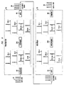
- the input data stream 10 is divided into portions. 35.1-35.N, each of which is allocated to a respective one of N wavelength channels.
- these N channels will be assembled into the transmitted optical signal 20 in such a way that the pulse sequence of input data stream 10 is preserved. That is, each pair of features that occur in a certain order in data stream 10 will be represented by features of data stream 20 that occur in the same order. This is achieved, e.g., by allocating a first feature to channel 1, the next to channel 2, and so forth up to channel N, and then repeating the same allocation pattern.
- the N channels are assembled to form data stream 20, they are then assembled in the order 1, 2, . . ., N.
- An extra measure of security can be added by scrambling the wavelength channels in such a way that the transmitted signal stream 20 does not preserve the original pulse sequence (or other sequence representing data content), but the receiver can recover the original pulse sequence from signal stream 20. This is achieved, e.g., by permuting the order of signal portions 35.1-35.N before they are combined in multiplexer 45, and in the receiver, applying the inverse permutation after the respective signal portions have been separated by demultiplexer 50.
- FIG. 9 shows a functional element in the transmitter, represented by scrambler 245, which permutes signal portions 35.1-35.N to produce permuted signal portions 250.1-250.N. This is done, e.g., by using electronic or optical delay lines to change the relative sequence of the N channels, while preserving relative timing within each channel individually.
- FIG. 9 also shows a functional element in the receiver, represented by unscrambler 260, which applies the inverse permutation to signal portions 255.1-255.N to produce signal portions 55.1-55.N, which can be combined to recover the original pulse sequence.
- the inverse permutation is also exemplarily carried out using electronic or optical delay lines.
- the system of FIG. 9 may use a fixed permutation and inverse permutation. However, even greater security is afforded by using a variable permutation (and its inverse).
- the permutation may be varied according to a schedule known in advance by the transmitter and receiver.
- the permutation may be varied at the transmitter, and identified at the receiver by header information that has been sent as part of transmitted signal 20.
- signal portions 255.1-255.N will typically be held in a buffer while the header information is decoded, and then subjected to the inverse permutation in accordance with the decoded header information.
Landscapes
- Engineering & Computer Science (AREA)
- Computer Networks & Wireless Communication (AREA)
- Signal Processing (AREA)
- Computer Security & Cryptography (AREA)
- Optical Communication System (AREA)
Abstract
Description
Claims (22)
- A method for transmitting data content provided in a data signal, comprising:a) assigning distinct portions of the data signal to two or more respective channels;b) for each channel, using corresponding assigned portions of the data signal to modulate an optical carrier at a respective wavelength associated with that channel; andc) transmitting an optical output signal that comprises modulated carrier energy at each of the respective wavelengths, such that data content is carried, in the transmitted optical output signal, by energy at two or more of the respective wavelengths.
- The method of claim 1, wherein the modulated carrier energy is transmitted in sequential segments, each such segment having a respective wavelength.
- The method of claim 1, wherein the assigning step comprises assigning, to each channel, those portions of the data signal that coincide with a recurring time window allocated to that channel.
- The method of claim 3, further comprising permuting the recurring time windows allocated to the channels, such that data content carried in the transmitted optical output signal occurs in a different sequence from the data content provided in the data signal.
- The method of claim 4, wherein the permuting step is carried out using delay lines.
- The method of claim 5 further comprising transmitting, as part of the optical output signal, information that describes how the time windows were permuted.
- The method of claim 1, wherein the transmitting step comprises launching the optical output signal into an optical fiber.
- The method of claim 1, wherein the transmitting step comprises launching the optical output signal into free space.
- The method of claim 1, wherein:a) the data signal is an electrical signal;b) the assigning step comprises deriving two or more electrical driver signals from the data signal, each driver signal corresponding to a respective channel; andc) the modulating step comprises using each driver signal to cause a respective optical emission device to emit an optical signal at a respective wavelength.
- The method of claim 1, wherein the data signal is an optical signal having a wavelength λD , and the modulating step comprises:a) providing optical radiation at two or more wavelengths to be referred to as coding wavelengths; andb) mixing a respective portion of the data signal with optical radiation at each of the coding wavelengths in a nonlinear optical device, thereby to generate modulated radiation having a wavelength different from the wavelength λD and the coding wavelengths.
- The method of claim 10, wherein:a) the assigning step comprises assigning, to each each channel, those portions of the data signal that coincide with a recurring time window allocated to that channel;b) the optical radiation at each of the coding wavelengths is provided in the form of a train of pulses;c) each train of pulses corresponds to a recurring time window allocated to one of the channels; andd) the respective wavelength associated with each of the channels is a wavelength of modulated radiation generated by said non-linear mixing.
- The method of claim 1, wherein:a) the data signal is an electrical signal;b) the method further comprises operating a tunable light source to produce output radiation that varies stepwise in wavelength according to a pattern; andc) the assigning and modulating steps comprise using the data signal to modulate the output radiation such that each portion of the data signal is modulated onto an assigned wavelength of output radiation.
- The method of claim 12, wherein the output radiation is generated by operating a voltage-tunable laser.
- The method of claim 12, wherein the pattern of wavelength variation defines respective, recurring time windows during which data content is to be allocated to corresponding wavelength channels.
- A method of optical communication, comprising:receiving an optical signal that contains energy in two or more distinct wavelength channels;assembling portions of the received optical signal, from distinct wavelength channels, into a single, sequential data stream; andrecovering data content from the assembled data stream.
- The method of claim 15, wherein:a) the method further comprises providing timing information that defines a succession of time windows for each of the channels; andb) the assembling of signal portions is carried out in accordance with the timing information, such that in the assembled data stream, each portion of the received optical signal falls in assigned time windows according to the channel in which such portion was received.
- The method of claim 16, wherein the received optical signal falls in time windows having a permuted sequence, and the method further comprises applying an inverse permutation to the time windows, such that data content carried in the received optical signal is restored to an original sequence.
- The method of claim 17, wherein the inverse permutation is carried out using delay lines.
- The method of claim 18, further comprising decoding, from the received optical signal, information that describes how the time windows were permuted.
- The method of claim 15, wherein:further comprising:a) the method further comprises optically demultiplexing the received signal, thereby to provide two or more single-channel optical signals;b) the method further comprises detecting each of the single-channel signals, thereby to provide two or more single-channel electronic signals; andc) the assembling step comprises electronically multiplexing the single-channel electronic signals.
- The method of claim 15, wherein:a) the method further comprises optically demultiplexing the received signal, thereby to provide two or more single-channel optical signals;b) the method further comprises shifting each of the single-channel signals into a common wavelength channel by non-linear optical mixing; andc) the assembling step is carried out by optical multiplexing.
- An optical communication system, comprising means arranged to carry out a method as claimed in any of the preceding claims.
Applications Claiming Priority (2)
| Application Number | Priority Date | Filing Date | Title |
|---|---|---|---|
| US262530 | 1999-03-04 | ||
| US09/262,530 US7272319B1 (en) | 1999-03-04 | 1999-03-04 | System and method for secure multiple wavelength communication on optical fibers |
Publications (2)
| Publication Number | Publication Date |
|---|---|
| EP1039669A2 true EP1039669A2 (en) | 2000-09-27 |
| EP1039669A3 EP1039669A3 (en) | 2005-09-07 |
Family
ID=22997891
Family Applications (1)
| Application Number | Title | Priority Date | Filing Date |
|---|---|---|---|
| EP00301382A Withdrawn EP1039669A3 (en) | 1999-03-04 | 2000-02-22 | System and method for secure multiple wavelength communication on optical fibers |
Country Status (4)
| Country | Link |
|---|---|
| US (1) | US7272319B1 (en) |
| EP (1) | EP1039669A3 (en) |
| JP (1) | JP2000278249A (en) |
| CA (1) | CA2298323A1 (en) |
Cited By (3)
| Publication number | Priority date | Publication date | Assignee | Title |
|---|---|---|---|---|
| WO2003084120A1 (en) * | 2002-03-28 | 2003-10-09 | Infineon Technologies Ag | Circuit arrangement for securing information exchange between a transmitter and a receiver |
| US7027735B2 (en) | 2002-04-03 | 2006-04-11 | Corning Incorporated | Unequal pulse spacer |
| WO2019053296A1 (en) * | 2017-09-18 | 2019-03-21 | Osram Gmbh | METHOD FOR LINEAR ENCODING OF SIGNALS FOR THE REDUNDANT TRANSMISSION OF DATA OVER MULTIPLE OPTICAL CHANNELS |
Families Citing this family (17)
| Publication number | Priority date | Publication date | Assignee | Title |
|---|---|---|---|---|
| CA2573981A1 (en) * | 2004-07-15 | 2006-02-23 | Essex Corporation | A private and secure optical communication system using an optical tapped delay line |
| FR2876234A1 (en) * | 2004-10-05 | 2006-04-07 | Laser Networks Soc Par Actions | SECURE OPTICAL TRANSMISSION |
| US7609968B2 (en) * | 2005-06-15 | 2009-10-27 | Nortel Networks Limited | Secure analog communication system using time and wavelength scrambling |
| US7761012B2 (en) * | 2006-01-12 | 2010-07-20 | Nec Laboratories America, Inc. | Optical communication system and method for generating dark return-to zero and DWDM optical MM-Wave generation for ROF downstream link using optical phase modulator and optical interleaver |
| EP2347483B1 (en) | 2008-11-04 | 2017-07-19 | Massachusetts Institute of Technology | External-cavity one-dimensional multi-wavelength beam combining of two-dimensional laser elements |
| US8744262B2 (en) | 2009-12-08 | 2014-06-03 | Vello Systems, Inc. | Optical subchannel routing, protection switching and security |
| RU2422885C1 (en) * | 2010-02-15 | 2011-06-27 | Михаил Яковлевич Яковлев | Fibre-optic data transmission system with unauthorised access protection |
| US8705741B2 (en) * | 2010-02-22 | 2014-04-22 | Vello Systems, Inc. | Subchannel security at the optical layer |
| US8614853B2 (en) | 2010-03-09 | 2013-12-24 | Massachusetts Institute Of Technology | Two-dimensional wavelength-beam-combining of lasers using first-order grating stack |
| US8531761B2 (en) | 2010-05-27 | 2013-09-10 | Massachusetts Institute Of Technology | High peak power optical amplifier |
| US9620928B2 (en) | 2010-07-16 | 2017-04-11 | Massachusetts Institute Of Technology | Continuous wave or ultrafast lasers |
| US9030953B2 (en) * | 2011-03-04 | 2015-05-12 | Alcatel Lucent | System and method providing resilient data transmission via spectral fragments |
| JP5799872B2 (en) * | 2012-03-28 | 2015-10-28 | 富士通株式会社 | Optical transmitter, optical receiver, and optical transmission method |
| WO2017034112A1 (en) * | 2015-08-24 | 2017-03-02 | 한국과학기술원 | High-speed communication system and method with enhanced security |
| CN108141288A (en) * | 2015-08-24 | 2018-06-08 | 韩国科学技术院 | High speed communication system and method with enhanced security |
| US10291326B2 (en) * | 2016-09-26 | 2019-05-14 | The Boeing Company | Communication systems and methods |
| US10992387B2 (en) * | 2019-09-12 | 2021-04-27 | Google Llc | Port replicator |
Family Cites Families (15)
| Publication number | Priority date | Publication date | Assignee | Title |
|---|---|---|---|---|
| US4100374A (en) | 1977-04-11 | 1978-07-11 | Bell Telephone Laboratories, Incorporated | Uniform permutation privacy system |
| JPS6430324A (en) | 1987-07-27 | 1989-02-01 | Advantest Corp | Continuous counter |
| JPH03169137A (en) | 1989-11-28 | 1991-07-22 | Hokuriku Nippon Denki Software Kk | Cryptographic system for on-line system |
| US5495356A (en) | 1993-04-30 | 1996-02-27 | Nec Research Institute, Inc. | Multidimensional switching networks |
| US5515194A (en) | 1993-05-28 | 1996-05-07 | Interdigital Technology Corporation | Optical interconnect for high speed processors |
| US5394489A (en) | 1993-07-27 | 1995-02-28 | At&T Corp. | Wavelength division multiplexed optical communication transmitters |
| FR2715015B1 (en) | 1994-01-07 | 1996-02-02 | Auffret Rene | Method and device for transmitting and routing packets in an optical network. |
| US5710650A (en) * | 1996-03-14 | 1998-01-20 | Alcatel Network Systems, Inc. | Dispersion-reducing multiple wavelength division multiplexing optical fiber transceiver and methods for using and assembling same |
| US6025944A (en) * | 1997-03-27 | 2000-02-15 | Mendez R&D Associates | Wavelength division multiplexing/code division multiple access hybrid |
| FR2765055B1 (en) | 1997-06-23 | 1999-09-24 | Alsthom Cge Alcatel | METHOD AND DEVICE FOR CONCATENING BINARY INFORMATION AND APPLICATION TO OPTICAL PACKET TRANSMISSION |
| US6256124B1 (en) * | 1998-05-08 | 2001-07-03 | All Optical Networks, Inc. | Combination photonic time and wavelength division multiplexer |
| DE19828614A1 (en) | 1998-06-26 | 1999-12-30 | Ams Optotech Vertrieb Gmbh | Transmission method for optical data using optical waveguide |
| US6233075B1 (en) * | 1999-01-25 | 2001-05-15 | Telcordia Technologies, Inc. | Optical layer survivability and security system |
| DE19927451A1 (en) | 1999-06-16 | 2000-12-21 | Alcatel Sa | Method for the transmission of data via an optical WDM transmission system, and WDM transmission system |
| WO2001031818A1 (en) * | 1999-10-28 | 2001-05-03 | Fujitsu Limited | Transmission system |
-
1999
- 1999-03-04 US US09/262,530 patent/US7272319B1/en not_active Expired - Fee Related
-
2000
- 2000-02-10 CA CA002298323A patent/CA2298323A1/en not_active Abandoned
- 2000-02-22 EP EP00301382A patent/EP1039669A3/en not_active Withdrawn
- 2000-03-03 JP JP2000058296A patent/JP2000278249A/en not_active Abandoned
Cited By (5)
| Publication number | Priority date | Publication date | Assignee | Title |
|---|---|---|---|---|
| WO2003084120A1 (en) * | 2002-03-28 | 2003-10-09 | Infineon Technologies Ag | Circuit arrangement for securing information exchange between a transmitter and a receiver |
| US7457365B2 (en) | 2002-03-28 | 2008-11-25 | Infineon Technologies Ag | Circuit arrangement having a transmitter and a receiver |
| US7027735B2 (en) | 2002-04-03 | 2006-04-11 | Corning Incorporated | Unequal pulse spacer |
| WO2019053296A1 (en) * | 2017-09-18 | 2019-03-21 | Osram Gmbh | METHOD FOR LINEAR ENCODING OF SIGNALS FOR THE REDUNDANT TRANSMISSION OF DATA OVER MULTIPLE OPTICAL CHANNELS |
| US11476978B2 (en) | 2017-09-18 | 2022-10-18 | Osram Gmbh | Method for linear encoding of signals for the redundant transmission of data via multiple optical channels |
Also Published As
| Publication number | Publication date |
|---|---|
| JP2000278249A (en) | 2000-10-06 |
| US7272319B1 (en) | 2007-09-18 |
| CA2298323A1 (en) | 2000-09-04 |
| EP1039669A3 (en) | 2005-09-07 |
Similar Documents
| Publication | Publication Date | Title |
|---|---|---|
| US7272319B1 (en) | System and method for secure multiple wavelength communication on optical fibers | |
| US10110322B2 (en) | Secure open-air communication system utilizing multichannel decoyed transmission | |
| EP1060589B1 (en) | Method and apparatus for improving spectral efficiency in wavelength division multiplexed transmission systems | |
| US8737618B2 (en) | Secure key distribution for optical code division multiplexed based optical encryption | |
| EP0938197A2 (en) | High capacity chirped-pulse wavelength-division multiplexed communication method and apparatus | |
| KR20010043970A (en) | Multiwavelength mode-locked dense wavelength division multiplexed optical communication systems | |
| JPH08256128A (en) | Optical WDM communication device | |
| US6865344B1 (en) | Code-switched optical networks | |
| US8705741B2 (en) | Subchannel security at the optical layer | |
| US7437082B1 (en) | Private optical communications systems, devices, and methods | |
| US7065298B1 (en) | Code-based optical networks, methods, and apparatus | |
| US20020071152A1 (en) | System and method of all optical label swapping using two-stage optical wavelength converters | |
| CA2351682C (en) | Code-based optical networks, methods, and apparatus | |
| US20030095312A1 (en) | Common clock optical fiber transmission system | |
| US6128114A (en) | Method of and system for transmitting data | |
| US7609968B2 (en) | Secure analog communication system using time and wavelength scrambling | |
| US6407837B1 (en) | Use of bandwidth efficient modulation techniques in a wavelength division multiplexed optical link | |
| EP2548319A1 (en) | System and methods for ocdm-based optical encryption using subsets of phase-locked frequency lines | |
| JP3286094B2 (en) | Optical WDM Network System | |
| JPH10242942A (en) | Optical transmitter and parallel encoding transmission system using the same | |
| HK1092612A (en) | Secure open-air communication system utilyzing multi-channel decoyed transmission |
Legal Events
| Date | Code | Title | Description |
|---|---|---|---|
| PUAI | Public reference made under article 153(3) epc to a published international application that has entered the european phase |
Free format text: ORIGINAL CODE: 0009012 |
|
| AK | Designated contracting states |
Kind code of ref document: A2 Designated state(s): AT BE CH CY DE DK ES FI FR GB GR IE IT LI LU MC NL PT SE |
|
| AX | Request for extension of the european patent |
Free format text: AL;LT;LV;MK;RO;SI |
|
| RIC1 | Information provided on ipc code assigned before grant |
Ipc: 7H 04K 1/00 B Ipc: 7H 04J 14/02 A |
|
| PUAL | Search report despatched |
Free format text: ORIGINAL CODE: 0009013 |
|
| AK | Designated contracting states |
Kind code of ref document: A3 Designated state(s): AT BE CH CY DE DK ES FI FR GB GR IE IT LI LU MC NL PT SE |
|
| AX | Request for extension of the european patent |
Extension state: AL LT LV MK RO SI |
|
| 17P | Request for examination filed |
Effective date: 20060221 |
|
| AKX | Designation fees paid |
Designated state(s): DE FR GB |
|
| STAA | Information on the status of an ep patent application or granted ep patent |
Free format text: STATUS: THE APPLICATION HAS BEEN WITHDRAWN |
|
| 18W | Application withdrawn |
Effective date: 20060620 |