EP1039585A2 - Electrical connector terminal arrangement - Google Patents
Electrical connector terminal arrangement Download PDFInfo
- Publication number
- EP1039585A2 EP1039585A2 EP00105196A EP00105196A EP1039585A2 EP 1039585 A2 EP1039585 A2 EP 1039585A2 EP 00105196 A EP00105196 A EP 00105196A EP 00105196 A EP00105196 A EP 00105196A EP 1039585 A2 EP1039585 A2 EP 1039585A2
- Authority
- EP
- European Patent Office
- Prior art keywords
- wall
- contact portion
- electrical connector
- terminal
- mating
- Prior art date
- Legal status (The legal status is an assumption and is not a legal conclusion. Google has not performed a legal analysis and makes no representation as to the accuracy of the status listed.)
- Withdrawn
Links
Images


Classifications
-
- H—ELECTRICITY
- H01—ELECTRIC ELEMENTS
- H01R—ELECTRICALLY-CONDUCTIVE CONNECTIONS; STRUCTURAL ASSOCIATIONS OF A PLURALITY OF MUTUALLY-INSULATED ELECTRICAL CONNECTING ELEMENTS; COUPLING DEVICES; CURRENT COLLECTORS
- H01R13/00—Details of coupling devices of the kinds covered by groups H01R12/70 or H01R24/00 - H01R33/00
- H01R13/02—Contact members
- H01R13/28—Contacts for sliding cooperation with identically-shaped contact, e.g. for hermaphroditic coupling devices
-
- H—ELECTRICITY
- H01—ELECTRIC ELEMENTS
- H01R—ELECTRICALLY-CONDUCTIVE CONNECTIONS; STRUCTURAL ASSOCIATIONS OF A PLURALITY OF MUTUALLY-INSULATED ELECTRICAL CONNECTING ELEMENTS; COUPLING DEVICES; CURRENT COLLECTORS
- H01R24/00—Two-part coupling devices, or either of their cooperating parts, characterised by their overall structure
- H01R24/84—Hermaphroditic coupling devices
-
- H—ELECTRICITY
- H01—ELECTRIC ELEMENTS
- H01R—ELECTRICALLY-CONDUCTIVE CONNECTIONS; STRUCTURAL ASSOCIATIONS OF A PLURALITY OF MUTUALLY-INSULATED ELECTRICAL CONNECTING ELEMENTS; COUPLING DEVICES; CURRENT COLLECTORS
- H01R12/00—Structural associations of a plurality of mutually-insulated electrical connecting elements, specially adapted for printed circuits, e.g. printed circuit boards [PCB], flat or ribbon cables, or like generally planar structures, e.g. terminal strips, terminal blocks; Coupling devices specially adapted for printed circuits, flat or ribbon cables, or like generally planar structures; Terminals specially adapted for contact with, or insertion into, printed circuits, flat or ribbon cables, or like generally planar structures
- H01R12/70—Coupling devices
- H01R12/71—Coupling devices for rigid printing circuits or like structures
- H01R12/712—Coupling devices for rigid printing circuits or like structures co-operating with the surface of the printed circuit or with a coupling device exclusively provided on the surface of the printed circuit
- H01R12/716—Coupling device provided on the PCB
Definitions
- This invention generally relates to the art of electrical connectors and, particularly, to a terminal arrangement in an electrical connector, such as in a hermaphroditic electrical connector.
- an electrical connector includes some form of dielectric or insulating housing which mounts one or more conductive electrical terminals.
- the terminals have contact portions which are adapted for engaging the contact portions of the terminals of a complementary mating electrical connector or other connecting device.
- a pair of mating connectors are interconnected for establishing one or more electrical circuits through the assembly interface.
- Electrical connectors are used in a wide variety of applications. They may interconnect discrete electrical wires or they may interconnect a plurality of printed circuit boards or they may interconnect discrete wires with circuit traces on a circuit board, for instance. Electrical connectors also are used in a wide variety of environments, such as through panels or backplanes as well as in "drawer” applications, for instance.
- interconnecting electrical connectors are complex and expensive, involving one type of connector (such as a male or plug connector) and still another type of connector (such as a female or receptacle connector).
- a pair of hermaphroditic connectors are used in an electrical connector assembly to simplify the assembly and reduce its costs.
- One type of hermaphroditic connector system includes a pair of hermaphroditic connectors having opposed mating faces which are juxtaposed generally along a plane when the connectors are mated. The connectors are adapted for mating in directions generally parallel to the plane of the mating faces.
- the present invention is directed to solving these various problems and to providing simple, inexpensive and effective hermaphroditic electrical connectors.
- An object, therefore, of the invention is to provide an electrical connector with a new and improved terminal system or arrangement.
- Another object of the invention is to provide a new and improved electrical connector assembly including a pair of hermaphroditic connectors employing the terminal system.
- an electrical connector assembly includes a pair of hermaphroditic connectors having opposed mating faces which are juxtaposed generally along a plane when the connectors are mated.
- the connectors are adapted for mating in either opposite direction generally parallel to the plane of the mating faces.
- Each hermaphroditic connector includes a housing having a wall at the mating face of the connector.
- the wall extends in the mating direction and includes opposite wall ends.
- At least one terminal is mounted on the housing and has a contact portion spaced outwardly of the wall for flexing toward and away from the wall generally perpendicular to the mating direction.
- the contact portion has a first end anchored at one end of the wall and a second end engageable with the opposite end of the wall and slidable relative thereto in the mating direction.
- the wall has an edge at the opposite end thereof.
- the second end of the contact portion of the terminal has a hook for embracing the edge of the wall.
- the contact portion of the terminal is bowed outwardly of the wall at a point intermediate the first and second ends of the contact portion.
- a plurality of the terminals are spaced along the housing at the mating face of the connector.
- a feature of the invention comprises a projection behind the outwardly bowed contact portion of the terminal intermediate the first and second ends thereof.
- the projection prevents overtravel of the contact portion in flexing toward the wall.
- the wall is tapered on opposite sides of the projection.
- the invention contemplates that the housing be fabricated of dielectric plastic material, and the housing may be overmolded about at least a portion of the terminal to anchor the first end of the contact portion at the one end of the wall.
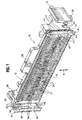
- a hermaphroditic electrical connector generally designated 10.
- a pair of the hermaphroditic connectors are shown in mated condition in Figure 4 and will be described hereinafter.
- hermaphroditic connector 10 includes an elongated dielectric housing, generally designated 12, defining a mating face, generally designated 14, whereby the mating faces of a pair of the connectors are juxtaposed generally along a plane when the connectors are mated in the direction of double-headed arrow "M".
- complementary interengaging latch means are provided on housing 12 of each connector 10 to lock a pair of the connectors against unmating in a direction generally perpendicular to the plane of mating faces 14.
- the complementary interengaging latch means are provided by a locking hook, generally designated 16, at one end of the housing for embracing an engaging flange, generally designated 18, at the opposite end of the housing of the mating connector.
- Figure 2 shows a pair of mounting posts 20 depending from opposite ends of the housing for insertion into appropriate mounting holes in a printed circuit board (not shown).
- Figure 2 also shows a plurality of standoffs 22 at the bottom of the housing for elevating the housing slightly above the surface of the printed circuit board.
- a pair of support ribs 23 extend transversely of the longitudinal direction of the housing.
- Mating face 14 of each hermaphroditic connector 10 actually is defined by a plurality of longitudinally spaced ribs 24 defining a plurality of grooves 26 therebetween.
- a plurality of terminals are mounted in the housing and include contact portions disposed in the grooves between the ribs, as will be described in greater detail hereinafter.
- an upwardly projecting pull tab 28 is provided intermediate opposite ends of housing 12. This pull tab can be grasped by an operator with a pair of pliers.
- a pair of pull tabs 30 also are provided projecting from opposite ends of the housing, again for grasping between the thumb and forefinger of an operator.
- Locking hook 16 and engaging flange 18 which define the complementary interengaging latch means between a pair of the hermaphroditic connectors 10 have opposing abutment surfaces that are elongated in the mating direction of the connectors and which are configured with inclined ramp portions to prevent the housings from binding when the connectors are mated in slightly skewed orientations. More particularly, locking hook 16 has two inner sides 32 and an edge 34 all with inclined ramp portions 38 and inner sides 33 each comprising one flat surface which define abutment surfaces that are elongated in the mating direction of the connector. Inner sides 32 and edge 34 have "non-binding" configurations.
- Each inner side 32 and edge 34 include a central, generally flat abutment portion 36 which is generally parallel to the mating direction of the connectors.
- Inclined ramp portions 38 are formed at opposite ends of each central abutment portion 36 in the mating direction of the connectors. These inclined ramps minimize binding of the housings of the connectors when attempts are made to mate the connectors in relatively skewed orientations.
- engaging flange 18 of each hermaphroditic connector has a generally rectangular cross-section defining two sides 40 and slot 46 all with inclined ramp portions 44 and two sides 41 each comprising one flat surface.
- the two sides 40, two sides 41 and slot 46 of the engaging flange define an abutment surface that is elongated in the mating direction of the connectors and which oppose the four inner sides 32, 33 and edge 34 of locking hook 16 of the mating connector.
- Sides 40 and slot 46 of engaging flange 18 include a generally flat, central abutment portion 42 in the mating direction of connectors. Edge 34 cooperates with slot 46.
- FIG 4 shows two hermaphroditic connectors 10 in mated condition. It can be seen that engaging flange 18 of each hermaphroditic connector is embraced by the locking hook 16 of the other hermaphroditic connector in a pair of the connectors.
- the locking hooks and the engaging flanges form complementary interengaging latch means to lock the connectors against unmating in a direction generally perpendicular to the plane of mating faces 14 of the connectors.
- FIGS 5 and 6 show two of the plurality of terminals, generally designated 50, which are mounted on housing 12 and which are spaced along the elongated housing.
- the housing includes a wall 52 running the length thereof and from which ribs 24 project at mating face 14 of the connector.
- the wall extends in the mating direction of the terminal and includes a top end 52a and a bottom end 52b.
- Each terminal 50 includes a contact portion, generally designated 54, disposed within a groove between a pair of ribs 24.
- the contact portion bows outwardly from housing wall 52 and mating face 14.
- the contact portion has a flat contact section 54a and ramp sections 54b extending from the contact section back toward the housing wall.
- contact portion 54 of each terminal 50 includes a first, fixed end 56 anchored to housing 12 at bottom end 52b of wall 52 and a second, free end 58 which is engageable with the top end 52a of wall 52 and slidable relative thereto in the mating direction of the connectors.
- Contact portion 54 particularly contact section 54a thereof, can flex toward and away from wall 50 upon abutting engagement with the contact portion of a corresponding terminal of the mating hermaphroditic connector.
- contact portion 54 flexes inwardly toward wall 52 in the direction of arrow "A”. This causes the free end 58 of the contact portion to move upwardly in the direction of arrow "B". The result is that there is very little shifting of the contact position with the terminal system or arrangement of the invention.
- free end 58 of contact portion 54 of each terminal 50 includes a hook 60 which is bent around a top edge 62 of housing wall 52 and embraces top end 52a of the wall. This prevents contact portion 54 from moving outwardly away from the wall.
- Each terminal includes a mounting leg 64 disposed within a channel 66 in housing 12 to anchor fixed end 56 of the contact portion. It is contemplated that housing 12 can be unitarily molded of dielectric material such as plastic or the like, and the housing can be overmolded about mounting legs 64 of the terminals to anchor the terminals in the housing.
- terminal tails 68 are bent downwardly to form terminal tails 68 for insertion into appropriate holes in the printed circuit board and for connection, as by soldering, to circuit traces on the board and/or in the holes. It can be seen in Figures 5 and 6 that the terminal tails of alternating terminals are offset to define two rows of terminal tails longitudinally of the connector.
- wall 52 of housing 12 is provided with a projection 70 immediately behind contact section 54a of contact portion 54 of each terminal. These projections prevent overtravel of the contact portions in flexing toward wall 52.
- the wall is tapered, as at 70a, on opposite sides of projection 70 to eliminate any abrupt recesses in the front face of the wall and into which the contact portion of the terminal might be forced.
Landscapes
- Details Of Connecting Devices For Male And Female Coupling (AREA)
- Coupling Device And Connection With Printed Circuit (AREA)
Abstract
Description
Claims (20)
- An electrical connector assembly including a pair of hermaphroditic connectors (10) having opposed mating faces (14) which are juxtaposed generally along a plane when the connectors are mated, with the connectors being adapted for mating in either opposite direction (M) generally parallel to said plane of the mating faces (14), each hermaphroditic connector (10) comprising:a housing (12) including a wall (52) at the mating face (14) of the connector, the wall extending in said mating direction (M) and including opposite ends (52a,52b); andat least one terminal (50) mounted on the housing and having a contact portion (54) spaced outwardly of said wall (52) for flexing toward and away from the wall generally perpendicular to said mating direction (M), the contact portion having a first end (56) anchored at one end (52b) of the wall and a second end (58) engageable with the opposite end (52a) of the wall and slidable relative thereto in said mating direction (M).
- The electrical connector assembly of claim 1 wherein said housing (12) is a plastic housing overmolded about at least a portion (64) of the terminal (50) to anchor the first end (56) of the contact portion (54) at said one end (52b) of the wall (52).
- The electrical connector assembly of claim 1 wherein said wall (52) has an edge (62) at said opposite end (52a) thereof, and said second end (58) of the contact portion (54) of the terminal (50) has a hook (60) for embracing said edge of the wall.
- The electrical connector assembly of claim 1 wherein said wall (52) includes a projection (70) behind the contact portion (54) of the terminal (50) intermediate said first and second ends thereof to prevent overtravel of the contact portion in flexing toward the wall.
- The electrical connector assembly of claim 4 wherein said wall (52) is tapered (70a) on opposite sides of said projection (70).
- The electrical connector assembly of claim 1 wherein said contact portion (54) of the terminal (50) is bowed outwardly of said wall (52) at a point intermediate the first and second ends (56,58) of the contact portion (54).
- The electrical connector assembly of claim 6 wherein said wall (52) includes a projection (70) behind the contact portion (54) of the terminal (50) intermediate said first and second ends (56,58) thereof to prevent overtravel of the contact portion in flexing toward the wall.
- The electrical connector assembly of claim 1, including a plurality of said terminals (50) spaced along the housing (12) at the mating face (14) of the connector (10).
- An electrical connector assembly including a pair of hermaphroditic connectors (10) having opposed mating faces (14) which are juxtaposed generally along a plane when the connectors are mated, with the connectors being adapted for mating in either opposite direction (M) generally parallel to said plane of the mating faces (14), each hermaphroditic connector (10) comprising:a housing (12) including a wall (52) at the mating face (14) of the connector, the wall extending in said mating direction (M) and including opposite ends (52a,52b) and an edge (62); anda plurality of terminals (50) mounted on the housing (12) and spaced along the mating face (14) of the connector, each terminal including a contact portion (54) bowed outwardly of said wall to be spaced therefrom for flexing toward and away from the wall generally perpendicular to said mating direction (M), the contact portion (54) having a first end (56) anchored at one end (52b) of the wall (52) and a second end (58) engageable with the opposite end (52a) of the wall and slidable relative thereto in said mating direction (M), and the second end (58) of the contact portion (54) having a hook (60) for embracing said edge (62) of the wall (52).
- The electrical connector assembly of claim 9 wherein said housing (12) is a plastic housing overmolded about at least a portion (64) of the terminal (50) to anchor the first end (56) of the contact portion (54) at said one end (52b) of the wall (52).
- The electrical connector assembly of claim 9 wherein said wall (52) includes a projection (70) behind the contact portion (54) of the terminal (50) intermediate said first and second ends thereof to prevent overtravel of the contact portion in flexing toward the wall.
- The electrical connector assembly of claim 11 wherein said wall (52) is tapered (70a) on opposite sides of said projection (70).
- An electrical connector (10) having a mating face (14) along a plane when the connector is mated with a complementary connector, comprising:a housing (12) including a wall (52) at the mating face (14) of the connector, the wall extending generally parallel to said plane and including opposite ends (52a,52b); andat least one terminal (50) mounted on the housing (12) and having a contact portion (54) spaced outwardly of said wall (52) for flexing toward and away from the wall generally perpendicular to said mating face (14), the contact portion (54) having a first end (56) anchored at one end (52b) of the wall and a second end (58) engageable with the opposite end (52a) of the wall and slidable relative thereto generally parallel to the mating face (14).
- The electrical connector of claim 13 wherein said housing (12) is a plastic housing overmolded about at least a portion (64) of the terminal (50) to anchor the first end (56) of the contact portion (54) at said one end (52b) of the wall (52).
- The electrical connector of claim 13 wherein said wall (52) has an edge (62) at said opposite end (52a) thereof, and said second end (58) of the contact portion (54) of the terminal (50) has a hook (60) for embracing said edge of the wall.
- The electrical connector of claim 13 wherein said wall (52) includes a projection (70) behind the contact portion (54) of the terminal (50) intermediate said first and second ends thereof to prevent overtravel of the contact portion in flexing toward the wall.
- The electrical connector of claim 16 wherein said wall (52) is tapered (70a) on opposite sides of said projection (70).
- The electrical connector of claim 13 wherein said contact portion (54) of the terminal (50) is bowed outwardly of said wall (52) at a point intermediate the first and second ends (56,58) of the contact portion (54).
- The electrical connector of claim 18 wherein said wall (52) includes a projection (70) behind the contact portion (54) of the terminal (50) intermediate said first and second ends (56,58) thereof to prevent overtravel of the contact portion in flexing toward the wall.
- The electrical connector of claim 13, including a plurality of said terminals (50) spaced along the housing (12) at the mating face (14) of the connector (10).
Applications Claiming Priority (2)
| Application Number | Priority Date | Filing Date | Title |
|---|---|---|---|
| US09/273,136 US6162081A (en) | 1999-03-19 | 1999-03-19 | Electrical connector terminal arrangement |
| US273136 | 1999-03-19 |
Publications (2)
| Publication Number | Publication Date |
|---|---|
| EP1039585A2 true EP1039585A2 (en) | 2000-09-27 |
| EP1039585A3 EP1039585A3 (en) | 2001-08-16 |
Family
ID=23042688
Family Applications (1)
| Application Number | Title | Priority Date | Filing Date |
|---|---|---|---|
| EP00105196A Withdrawn EP1039585A3 (en) | 1999-03-19 | 2000-03-13 | Electrical connector terminal arrangement |
Country Status (5)
| Country | Link |
|---|---|
| US (1) | US6162081A (en) |
| EP (1) | EP1039585A3 (en) |
| JP (1) | JP3355403B2 (en) |
| CN (1) | CN1199322C (en) |
| TW (1) | TW449155U (en) |
Cited By (1)
| Publication number | Priority date | Publication date | Assignee | Title |
|---|---|---|---|---|
| EP1039590A3 (en) * | 1999-03-19 | 2002-02-13 | Molex Incorporated | Electrical connector assembly |
Families Citing this family (7)
| Publication number | Priority date | Publication date | Assignee | Title |
|---|---|---|---|---|
| US6368162B1 (en) * | 1999-08-03 | 2002-04-09 | Kerry L. Reetz | Temperature resistive electrical distribution block |
| TW520101U (en) * | 2002-01-16 | 2003-02-01 | Hon Hai Prec Ind Co Ltd | Electrical connector component |
| JP4521351B2 (en) * | 2005-10-17 | 2010-08-11 | ホシデン株式会社 | Board connector |
| US20080076305A1 (en) * | 2006-09-25 | 2008-03-27 | Alltop Technology Co., Ltd. | Connector base structures for a connector |
| US7785152B2 (en) * | 2008-04-22 | 2010-08-31 | Hon Hai Precision Ind. Co., Ltd | High density connector having two-leveled contact interface |
| TWI629841B (en) * | 2016-07-29 | 2018-07-11 | 英屬開曼群島商鴻騰精密科技股份有限公司 | Electrical connector and manufacturing method of the same |
| JP2024064484A (en) | 2022-10-28 | 2024-05-14 | ヒロセ電機株式会社 | Connector device that can be connected to the same type connector |
Family Cites Families (9)
| Publication number | Priority date | Publication date | Assignee | Title |
|---|---|---|---|---|
| US4266845A (en) * | 1979-08-30 | 1981-05-12 | Iizuka Electric Industry Company Limited | Resilient contact member of jack for use in conjunction with a pin-plug |
| JPS6079681A (en) * | 1983-09-28 | 1985-05-07 | モレツクス・インコ−ポレ−テツド | Electric connector with hinge |
| US4737118A (en) * | 1985-12-20 | 1988-04-12 | Amp Incorporated | Hermaphroditic flat cable connector |
| US5183409A (en) * | 1991-04-15 | 1993-02-02 | Eric Clever | Hermaphroditic multiple contact connector |
| US5161985A (en) * | 1991-08-08 | 1992-11-10 | Robinson Nugent, Inc. | Board to board interconnect |
| US5199884A (en) * | 1991-12-02 | 1993-04-06 | Amp Incorporated | Blind mating miniature connector |
| US5575674A (en) * | 1994-07-29 | 1996-11-19 | The Whitaker Corporation | Connector adapted for hermaphroditic construction |
| US5520545A (en) * | 1994-11-21 | 1996-05-28 | The Whitaker Corporation | Variable orientation, surface mounted hermaphroditic connector |
| US5727961A (en) * | 1996-04-30 | 1998-03-17 | The Whitaker Corporation | Two-way transversely matable electrical connector |
-
1999
- 1999-03-19 US US09/273,136 patent/US6162081A/en not_active Expired - Lifetime
-
2000
- 2000-02-10 TW TW089202315U patent/TW449155U/en unknown
- 2000-03-13 EP EP00105196A patent/EP1039585A3/en not_active Withdrawn
- 2000-03-17 JP JP2000075019A patent/JP3355403B2/en not_active Expired - Fee Related
- 2000-03-17 CN CNB001043323A patent/CN1199322C/en not_active Expired - Fee Related
Cited By (1)
| Publication number | Priority date | Publication date | Assignee | Title |
|---|---|---|---|---|
| EP1039590A3 (en) * | 1999-03-19 | 2002-02-13 | Molex Incorporated | Electrical connector assembly |
Also Published As
| Publication number | Publication date |
|---|---|
| TW449155U (en) | 2001-08-01 |
| JP2000277199A (en) | 2000-10-06 |
| JP3355403B2 (en) | 2002-12-09 |
| US6162081A (en) | 2000-12-19 |
| CN1267933A (en) | 2000-09-27 |
| EP1039585A3 (en) | 2001-08-16 |
| CN1199322C (en) | 2005-04-27 |
Similar Documents
| Publication | Publication Date | Title |
|---|---|---|
| EP0706240B1 (en) | Board to board electrical connectors | |
| US6244887B1 (en) | Electrical connector assembly | |
| EP0795929B1 (en) | Electric connector assembly with improved retention characteristics | |
| KR100191747B1 (en) | Low profile surface mountable electrical connector assembly | |
| US5161985A (en) | Board to board interconnect | |
| US6811411B1 (en) | Board-to-board electrical connector assembly | |
| US6210240B1 (en) | Electrical connector with improved terminal | |
| EP0660445B1 (en) | Electrical connector with improved contact retention | |
| JP2009218221A (en) | Board-to-board electrical connector assembly | |
| US5525072A (en) | Electrical connector assembly for interconnecting a flat cable to a circuit board | |
| US20020142629A1 (en) | Board mounted electrical connector assembly | |
| US5921785A (en) | Electrical connector for flat cables | |
| US4474418A (en) | Electrical connector assembly | |
| US6830485B2 (en) | Electrical connector with a terminal pin stabilizing plate | |
| US6074230A (en) | Hermaphroditic electrical connectors | |
| US6162081A (en) | Electrical connector terminal arrangement | |
| US4192568A (en) | Connector assembly and improved connector plug | |
| IE55831B1 (en) | Low profile electrical connector assembly | |
| US6475017B1 (en) | Electrical connector with latch | |
| US6273748B1 (en) | Electrical connector assembly | |
| US5980307A (en) | Strain relief system for holding cables to circuit boards | |
| US6302722B1 (en) | Mating/unmating system for electrical connectors | |
| EP0549908A2 (en) | Electrical terminal assembly with terminal lock | |
| GB2198597A (en) | An electrical connector assembly and a housing therefor | |
| WO2004105191A1 (en) | Memory card connector |
Legal Events
| Date | Code | Title | Description |
|---|---|---|---|
| PUAI | Public reference made under article 153(3) epc to a published international application that has entered the european phase |
Free format text: ORIGINAL CODE: 0009012 |
|
| AK | Designated contracting states |
Kind code of ref document: A2 Designated state(s): DE FR GB IT |
|
| AX | Request for extension of the european patent |
Free format text: AL;LT;LV;MK;RO;SI |
|
| PUAL | Search report despatched |
Free format text: ORIGINAL CODE: 0009013 |
|
| AK | Designated contracting states |
Kind code of ref document: A3 Designated state(s): AT BE CH CY DE DK ES FI FR GB GR IE IT LI LU MC NL PT SE |
|
| AX | Request for extension of the european patent |
Free format text: AL;LT;LV;MK;RO;SI |
|
| 17P | Request for examination filed |
Effective date: 20020206 |
|
| AKX | Designation fees paid |
Free format text: DE FR GB IT |
|
| STAA | Information on the status of an ep patent application or granted ep patent |
Free format text: STATUS: THE APPLICATION HAS BEEN WITHDRAWN |
|
| 18W | Application withdrawn |
Withdrawal date: 20021121 |