EP1039465A2 - Pickup guide mechanism - Google Patents
Pickup guide mechanism Download PDFInfo
- Publication number
- EP1039465A2 EP1039465A2 EP00302364A EP00302364A EP1039465A2 EP 1039465 A2 EP1039465 A2 EP 1039465A2 EP 00302364 A EP00302364 A EP 00302364A EP 00302364 A EP00302364 A EP 00302364A EP 1039465 A2 EP1039465 A2 EP 1039465A2
- Authority
- EP
- European Patent Office
- Prior art keywords
- chassis
- guide shaft
- force
- shaft
- pickup
- Prior art date
- Legal status (The legal status is an assumption and is not a legal conclusion. Google has not performed a legal analysis and makes no representation as to the accuracy of the status listed.)
- Withdrawn
Links
- 230000003287 optical effect Effects 0.000 description 4
- 230000035939 shock Effects 0.000 description 3
- 230000001105 regulatory effect Effects 0.000 description 2
- 238000000034 method Methods 0.000 description 1
- 238000000465 moulding Methods 0.000 description 1
- 239000011347 resin Substances 0.000 description 1
- 229920005989 resin Polymers 0.000 description 1
Images



Classifications
-
- G—PHYSICS
- G11—INFORMATION STORAGE
- G11B—INFORMATION STORAGE BASED ON RELATIVE MOVEMENT BETWEEN RECORD CARRIER AND TRANSDUCER
- G11B7/00—Recording or reproducing by optical means, e.g. recording using a thermal beam of optical radiation by modifying optical properties or the physical structure, reproducing using an optical beam at lower power by sensing optical properties; Record carriers therefor
- G11B7/08—Disposition or mounting of heads or light sources relatively to record carriers
- G11B7/085—Disposition or mounting of heads or light sources relatively to record carriers with provision for moving the light beam into, or out of, its operative position or across tracks, otherwise than during the transducing operation, e.g. for adjustment or preliminary positioning or track change or selection
- G11B7/0857—Arrangements for mechanically moving the whole head
- G11B7/08582—Sled-type positioners
-
- G—PHYSICS
- G11—INFORMATION STORAGE
- G11B—INFORMATION STORAGE BASED ON RELATIVE MOVEMENT BETWEEN RECORD CARRIER AND TRANSDUCER
- G11B21/00—Head arrangements not specific to the method of recording or reproducing
- G11B21/02—Driving or moving of heads
- G11B21/08—Track changing or selecting during transducing operation
-
- G—PHYSICS
- G11—INFORMATION STORAGE
- G11B—INFORMATION STORAGE BASED ON RELATIVE MOVEMENT BETWEEN RECORD CARRIER AND TRANSDUCER
- G11B5/00—Recording by magnetisation or demagnetisation of a record carrier; Reproducing by magnetic means; Record carriers therefor
- G11B5/48—Disposition or mounting of heads or head supports relative to record carriers ; arrangements of heads, e.g. for scanning the record carrier to increase the relative speed
- G11B5/54—Disposition or mounting of heads or head supports relative to record carriers ; arrangements of heads, e.g. for scanning the record carrier to increase the relative speed with provision for moving the head into or out of its operative position or across tracks
- G11B5/55—Track change, selection or acquisition by displacement of the head
-
- G—PHYSICS
- G11—INFORMATION STORAGE
- G11B—INFORMATION STORAGE BASED ON RELATIVE MOVEMENT BETWEEN RECORD CARRIER AND TRANSDUCER
- G11B7/00—Recording or reproducing by optical means, e.g. recording using a thermal beam of optical radiation by modifying optical properties or the physical structure, reproducing using an optical beam at lower power by sensing optical properties; Record carriers therefor
- G11B7/12—Heads, e.g. forming of the optical beam spot or modulation of the optical beam
- G11B7/22—Apparatus or processes for the manufacture of optical heads, e.g. assembly
Definitions
- the present invention relates to a guide mechanism for guiding a pickup.
- the present invention relates to a guide mechanism for guiding a pickup with respect to an information recording face of an optical disk when it is applied to an optical disk reproducing device or an optical disk recording device.
- an optical disk reproducing device such as a CD player is capable of accurately reading information recorded on a CD as follows.
- the CD on which a row of pits having information are spirally recorded is rotated by a spindle motor, the row of pits form a track of information to be scanned.
- the track of information is accurately followed in the radial direction of the disk by a pickup attached to a pickup guide mechanism fixed to a casing of the CD player, the row of pits to be scanned can be optically read in order. In this way, information recorded on the CD can be read.
- Fig. 4 is a view showing the above conventional pickup guide mechanism.
- a shaft presser 103 to which a rod-shaped guide shaft 102, the rigidity of which is high, is attached.
- the guide shaft 102 can be positioned, and also when the other end portion of the guide shaft 102 is fixed by a countersunk head screw 104 screwed into a screw hole formed on the chassis 101, the guide shaft 102 can be arranged over an opening formed on the chassis, so that the guide shaft 102 can be positioned in the radial direction of a disk, that is, the guide shaft 102 can be positioned in the direction of arrow A. In this way, the guide shaft 102 can be fixed at a predetermined position shown in Fig. 4.
- the shaft presser 103 is made of resin by means of molding, and the bottom portion of the shaft presser 103 is fixed onto the chassis 101.
- the shaft presser 103 may be formed by raising a portion of the chassis 101.
- a pickup 105 is slidably supported by the guide shaft 102.
- a drive force of a carriage motor 106 is transmitted to a rack 108, which is fixed to the pickup 105, via a gear 107, an objective lens 109 of the pickup 105 can be moved in the radial direction of the disk.
- Fig. 5 is a view showing the guide shaft 102 fixed onto the chassis 101 by the countersunk head screw 104.
- the profile of the head portion of the countersunk head screw 104 is formed into a substantial cone shape having a tapered face.
- Taper angle ⁇ of the tapered face of the head portion of the countersunk head screw 104 is 90° by the standard size according to JIS (Japanese Industrial Standard), and the allowance does not exceed 90°.
- the central axis of the countersunk head screw 104 which is screwed to the chassis 101, is located at a predetermined position on central axis X of the guide shaft 102 as shown in Fig. 4, and the central axis of the countersunk head screw 104 makes a right angle with central axis X of the guide shaft 102.
- Component force Fz of force F fastens one end portion of the guide shaft 102 by the countersunk head screw 104 and the chassis 101, so that the guide shaft 102 can be fixed onto the chassis 101 by this fastening force Fz.
- Component force Fxy of force F the direction of which is horizontal, pushes the other end portion of the guide shaft 102 against the shaft presser 103, so that the guide shaft 102 can be positioned in the radial direction of the disk by this component force Fxy of force F.
- an angle formed between force F, which is perpendicular to the tapered face, and component force Fxy, which is horizontal, is ⁇ /2. Accordingly, for example, when angle ⁇ of the head portion of the countersunk head screw 104 is a standard size (90°), the angle formed between force F, which is perpendicular to the tapered face, and component force Fxy, which is horizontal, becomes 45°. Therefore, the intensity of component force Fz and that of component force Fxy become equal to each other.
- angle ⁇ of the head portion of the countersunk head screw 104 is formed in an allowance which deviates from the standard size, the angle formed between force F, which is perpendicular to the tapered face, and component force Fxy, which is horizontal, becomes smaller than 45°. In this case, an intensity of component force Fxy becomes a little lower than that of component force Fz.
- the guide shaft 102 When the guide shaft 102 receives this fastening force Fz and this pushing force Fxy, it can be fixed to a predetermined position on the chassis 101.
- the CD player on which the pickup guide mechanism is mounted When it is estimated that the CD player on which the pickup guide mechanism is mounted is incorporated into a vehicle or used as a portable CD player, it is necessary to give a sufficiently high intensity of fastening force so that the guide shaft 102 can not be easily disconnected from the chassis 101 even if it is given external vibration or shock caused when the CD player is carelessly dropped.
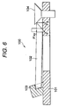
- FIG. 6 is a view showing a state in which the shaft presser 103 is deformed as described above.
- the guide shaft 102 pushes the shaft presser 103 by pushing force F'xy.
- the shaft presser 103 can not withstand this pushing force F'xy. Therefore, the guide presser 103 is deformed being pushed by the guide shaft 102.
- the guide shaft 102 is pushed in the thrust direction by the inclined face of the head portion of the countersunk head screw 104 which gradually proceeds downward being screwed into the chassis 101. As a result, the guide shaft 102 deviates from a predetermined position.
- the present invention has been made in view of the above problems. It is an object of the present invention to provide a pickup guide mechanism, the guide shaft of the pickup of which can be stably fixed at a predetermined position on the chassis by a sufficiently high intensity of fastening force, so that the pickup guide mechanism can withstand vibration and shock given from the outside.
- a pickup guide mechanism comprising: a shaft for guiding a pickup over an opening formed on a chassis; and fixing means for fixing the shaft to the chassis, the fixing means including a countersunk head screw, which is screwed to the chassis, a tapered face of a head portion of which pushes an end portion of the guide shaft, wherein the taper angle of the tapered face of the head portion exceeds 90°.
- the pushing force of the tapered face of the head portion of the countersunk head screw which pushes one end portion of the guide shaft it is possible to obtain a component force (pushing force) by which one end portion of the guide shaft is pushed in the horizontal direction of the fixing means so that no play is created in the guide shaft. Further, it is possible to increase an intensity of the component force (fastening force) for fixing the guide shaft to the chassis by fastening the guide shaft with the countersunk head screw and the chassis as compared with an intensity of the pushing force. Therefore, the guide shaft can be stably positioned by the pushing force without causing any play, and further the guide shaft can be fixed to the chassis by a sufficiently high intensity of fastening force. As a result, the pickup guide mechanism can be stably fixed at a predetermined position on the chassis while a sufficiently high intensity of fastening force is given to the guide shaft without causing any damage in each portion of the pickup guide mechanism.
- a pickup guide mechanism comprising: a shaft for guiding a pickup over an opening formed on a chassis; and fixing means for fixing the shaft to the chassis, the fixing means including a presser section, which is arranged on the chassis, coming into contact with one end portion of the guide shaft and positioning the guide shaft, and a countersunk head screw, which is screwed to the chassis, a tapered face of a head portion of which pushes the other end portion of the guide shaft toward the presser section, wherein the taper angle of the tapered face of the head portion exceeds 90°.
- the pushing force of the tapered face of the head portion of the countersunk head screw which pushes one end portion of the guide shaft it is possible to obtain a component force (pushing force) by which one end portion of the guide shaft of the fixing means is pushed in the horizontal direction so that no play is created in the guide shaft. Further, it is possible to increase an intensity of the component force (fastening force) for fixing the guide shaft to the chassis by fastening the guide shaft with the countersunk head screw and the chassis as compared with an intensity of the pushing force. Therefore, the guide shaft can be stably positioned by the pushing force without causing any play, and further the guide shaft can be fixed to the chassis by a sufficiently high intensity of fastening force. As a result, the pickup guide mechanism can be stably fixed at a predetermined position on the chassis while a sufficiently high intensity of fastening force is given to the guide shaft without causing any damage in each portion of the pickup guide mechanism.
- FIG. 1 is a view showing a pickup guide mechanism of an embodiment of the present invention.
- like reference characters are used to indicate like parts in Figs. 1 and 4, and the redundant explanations are omitted here.
- the pickup guide mechanism 1 includes a screw part 2 instead of the countersunk head screw 104 used in the conventional pickup guide mechanism 100 shown in Fig. 4.
- the pickup guide mechanism 1 includes a fixing means composed of a shaft presser 103 and a screw part 1.
- the fixing means is composed as follows. A recessed portion of the shaft presser 103 comes into contact with one end portion of the guide shaft 102, so that the guide shaft 102 can be positioned. The screw part 2 screwed into the chassis 101 fixes the other end portion of the guide shaft 102. Due to the foregoing, the guide shaft 102 is arranged over an opening formed on the chassis 101 in the radial direction of the disk, that is, the guide shaft 102 is arranged in the direction of arrow A in Fig. 1.
- the central axis of the screw part 2, which is screwed to the chassis 101, is located on central axis X of the guide shaft 102 arranged at a predetermined position as shown in Fig. 1, and the central axis of the countersunk head screw 104 makes a right angle with central axis X of the guide shaft 102.
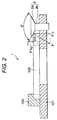
- Fig. 2 is a view showing the guide shaft 102 fixed onto the chassis 101 by the screw part 2.
- the screw part 2 is composed of a head portion 2a and screw portion 2b.
- the head portion 2a has a tapered face in the same manner as that of the above countersunk head screw 104, however, angle ⁇ ' of the head portion 2a, which is a taper angle of the tapered face of the head portion 2a, is formed to be in a range which is larger than 90° and smaller than 160°.
- the screw portion 2b of the screw part 2 is screwed to the chassis 101, so that the tapered face of the head portion 2a pushes the other end portion of the guide shaft 102 by force Fy'' which is perpendicular to the tapered face.
- the intensity of force F'' is sufficiently higher than that of force F shown in Fig. 5.
- the intensity of component force F''xy in the horizontal direction of force F'' is made to be equal to the intensity of component force Fxy in the horizontal direction created by the countersunk head screw 104 in the pickup guide mechanism 100 shown in Fig. 5.
- Force F'' becomes a fastening force for fixing the guide shaft 102 to the chassis 101 by fastening the other end portion of the guide shaft 102 with the screw part 2 and the chassis 101.
- Force F''xy becomes a pushing force for pushing the other end portion of the guide shaft 102 toward the shaft presser 103 in such a manner that the guide shaft 102 is pushed in the same horizontal direction as the radial direction of the disk (shown by arrow A in Fig. 1) so that one end portion of the guide shaft 102 can be pushed against the shaft presser 102 in the horizontal direction and the guide shaft 102 can be positioned in the radial direction of the disk.
- an angle formed by force F'' perpendicular to the tapered face and component force F''xy in the horizontal direction is ⁇ '/2. Since angle ⁇ ' of the head portion 2a is formed to be larger than 90°, the intensity of component force F''z in the vertical direction is higher than the intensity of component force F''xy in the horizontal direction.
- the intensity of component force F''z in the vertical direction is higher than the intensity of component force Fz in the vertical direction in the pickup guide mechanism 100 shown in Fig. 5.
- the intensity of component force F''z in the vertical direction of force F'' is higher than the intensity of component force F''xy in the horizontal direction.
- angle ⁇ ' of the head portion 2a is kept to be smaller than 150°.
- one end portion of the guide shaft 102 can be fixed to the chassis 101 by a high intensity of fastening force F''z, and at the same time one end portion of the guide shaft 102 can be pushed to the shaft presser 103 in the horizontal direction by the same intensity of pushing force F''xy. Therefore, the other end portion of the guide shaft can be stably positioned in the horizontal direction without creating any play while no damage is caused in the shaft presser 103 and no deformation is caused on the chassis 101, and further one end portion of the guide shaft can be fixed to the chassis by a sufficiently high fastening force. As a result, it is possible to stably fix the guide shaft 102 of the pickup guide mechanism 1 at a predetermined position on the chassis 101 by a sufficiently high intensity of fastening force without damaging each portion of the pickup guide mechanism 1.
- the screw part 2 to be screwed to the chassis 101 is arranged in such a manner that the central axis of the screw part 2 makes a right angle with central axis X of the guide shaft 102 (shown in Fig. 1) on central axis X. Therefore, all component force F''xy in the horizontal direction of force F'', which pushes the guide shaft 102 by the tapered face, pushes one end portion of the guide shaft 102 in the same direction as the radial direction of the disk.
- the present invention is not limited to the above specific embodiment. As shown by the pickup guide mechanism of another embodiment illustrated in Fig. 3, it is possible to adopt an arrangement in which a pushing force of the guide shaft 102 in the radial direction of the disk can be obtained by a portion of component force F''xy in the horizontal direction.
- the pickup guide mechanism 3 shown in Fig. 3 is an example in which the screw part 2 screwed to the chassis 101 of the pickup mechanism 1 shown in Fig. 1 deviates from central axis X.
- a protrusion 4 which is a position regulating means for regulating a position of the guide shaft on the chassis 101 in the horizontal direction.
- Force F'' becomes a fastening force for fixing the guide shaft 102 to the chassis 101 by fastening the other end portion of the guide shaft 102 with the screw part 2 and the chassis 101.
- Component force F''y the direction of which is the same as the radial direction (arrow A in Fig. 1) of the disk, of component force F''xy of force F'' in the horizontal direction becomes a pushing force for positioning the guide shaft 102 in the radial direction of the disk.
- Component force F''x in component force F''xy of force F'' in the horizontal direction which makes a right angle with the radial direction of the disk (arrow A in Fig. 1), makes the guide shaft 103 come into contact with the protrusion 4, so that the guide shaft 102 can be positioned at a predetermined position by this pushing force of component force F''x together with the shaft presser 103.
- the fixing means of the pickup guide mechanism 3 is composed of the shaft presser 103, screw part 1 and protrusion 4.
- component force F''xy in the horizontal direction can be divided into component forces of two directions. Therefore, when a position of the screw hole formed on the chassis 101 is appropriately changed from central axis X, it is possible to adjust a ratio of component force F''x to component force F''y. Therefore, the other end portion of the guide shaft can be stably positioned in the horizontal direction without creating any play while no damage is caused in the shaft presser 103 and no deformation is caused on the chassis 101, and further one end portion of the guide shaft can be fixed to the chassis by a sufficiently high fastening force. As a result, it is possible to stably fix the guide shaft 102 of the pickup guide mechanism 3 at a predetermined position on the chassis 101 by a sufficiently high intensity of fastening force without damaging each portion of the pickup guide mechanism 3.
- the present invention it is possible to obtain a component force (pushing force) for pushing and positioning the guide shaft in the horizontal direction without creating any play of the guide shaft in the horizontal direction, from the pushing force for pushing one end of the guide shaft by the tapered face of the head portion of the countersunk head screw. Further, it is possible to increase the intensity of a component force (fastening force) for fastening the guide shaft by the countersunk head screw and the chassis as compared with the intensity of the pushing force concerned. As a result, it is possible to stably position the guide shaft by a pushing force without causing any play, and at the same time it is possible to fix the guide shaft to the chassis by a sufficiently high intensity of fastening force. As a result, in the pickup guide mechanism, the guide shaft can be stably fixed at a predetermined position on the chassis by a sufficiently high intensity of fastening force without causing any damage in each portion.
Landscapes
- Physics & Mathematics (AREA)
- Optics & Photonics (AREA)
- Moving Of Heads (AREA)
Abstract
Description
Claims (2)
- A pickup guide mechanism comprising:a shaft for guiding a pickup over an opening formed on a chassis; andfixing means for fixing the shaft to the chassis, the fixing means including a countersunk head screw, which is screwed to the chassis, a tapered face of a head portion of which pushes an end portion of the guide shaft,
wherein the taper angle of the tapered face of the head portion exceeds 90°. - A pickup guide mechanism comprising:a shaft for guiding a pickup over an opening formed on a chassis; andfixing means for fixing the shaft to the chassis, the fixing means including a presser section, which is arranged on the chassis, for coming into contact with one end portion of the guide shaft and positioning the guide shaft, and a countersunk head screw, which is screwed to the chassis, a tapered face of a head portion of which pushes the other end portion of the guide shaft toward the presser section,
wherein the taper angle of the tapered face of the head portion exceeds 90°.
Applications Claiming Priority (2)
| Application Number | Priority Date | Filing Date | Title |
|---|---|---|---|
| JP7802599 | 1999-03-23 | ||
| JP11078025A JP2000276860A (en) | 1999-03-23 | 1999-03-23 | Pickup guiding mechanism |
Publications (2)
| Publication Number | Publication Date |
|---|---|
| EP1039465A2 true EP1039465A2 (en) | 2000-09-27 |
| EP1039465A3 EP1039465A3 (en) | 2001-09-26 |
Family
ID=13650283
Family Applications (1)
| Application Number | Title | Priority Date | Filing Date |
|---|---|---|---|
| EP00302364A Withdrawn EP1039465A3 (en) | 1999-03-23 | 2000-03-23 | Pickup guide mechanism |
Country Status (3)
| Country | Link |
|---|---|
| US (1) | US6353589B1 (en) |
| EP (1) | EP1039465A3 (en) |
| JP (1) | JP2000276860A (en) |
Families Citing this family (3)
| Publication number | Priority date | Publication date | Assignee | Title |
|---|---|---|---|---|
| WO2006095305A1 (en) * | 2005-03-10 | 2006-09-14 | Koninklijke Philips Electronics N.V. | Optical drive comprising spindle adjustment means |
| TWI268493B (en) * | 2005-08-11 | 2006-12-11 | Benq Corp | Carrying mechanism and optical disc drive using the same |
| US20080265918A1 (en) * | 2007-04-24 | 2008-10-30 | Protos Electronics, Inc. | Object-clamping lid subassembly of a test socket for testing electrical characteristics of an object |
Family Cites Families (3)
| Publication number | Priority date | Publication date | Assignee | Title |
|---|---|---|---|---|
| US4873598A (en) * | 1987-02-05 | 1989-10-10 | Fuji Photo Film Co., Ltd. | Mechanism for supporting and guiding a head carriage |
| KR970004685B1 (en) * | 1987-08-18 | 1997-04-02 | 소니 가부시키가이샤 | Head driving apparatus |
| JP2569957B2 (en) * | 1990-12-05 | 1997-01-08 | ティアック株式会社 | Head carriage drive |
-
1999
- 1999-03-23 JP JP11078025A patent/JP2000276860A/en active Pending
-
2000
- 2000-03-23 EP EP00302364A patent/EP1039465A3/en not_active Withdrawn
- 2000-03-23 US US09/533,662 patent/US6353589B1/en not_active Expired - Fee Related
Also Published As
| Publication number | Publication date |
|---|---|
| US6353589B1 (en) | 2002-03-05 |
| EP1039465A3 (en) | 2001-09-26 |
| JP2000276860A (en) | 2000-10-06 |
Similar Documents
| Publication | Publication Date | Title |
|---|---|---|
| KR100243191B1 (en) | Optical disk player | |
| US6445673B2 (en) | Optical pick-up feeding device | |
| US5764618A (en) | Pickup adjusting device in an optical disk player | |
| KR20010090444A (en) | Disk recording or playing device with pick-up inclination adjustment unit | |
| US6052358A (en) | Head feeding mechanism and optical pick-up feeding mechanism | |
| US6205111B1 (en) | Disk driving apparatus for reliably centering a meter-layer optical disk on which information is recorded | |
| US6385160B1 (en) | Pickup adjusting apparatus of a disk player | |
| KR100400339B1 (en) | Optical disk device | |
| US6493309B2 (en) | Pickup adjusting mechanism for a disc player | |
| US6353589B1 (en) | Pickup guide mechanism | |
| US20040027962A1 (en) | Disk device | |
| US6765859B2 (en) | Record and read apparatus | |
| US6912722B2 (en) | Disk drive and beam angle adjusting structure | |
| KR101050832B1 (en) | Disc Drive Unit, Disc Drive Unit, Optical Pickup Unit | |
| KR100439977B1 (en) | Optical pick-up control apparatus and optical write and read apparatus comprising thereof | |
| US20060190953A1 (en) | Disk recording/reproducer and method for fixing pickup of disc recorder/reproducer | |
| KR100189914B1 (en) | Pickup Tilt Adjuster of a Disc Player | |
| JPH09223353A (en) | Optical disk drive | |
| US20110258646A1 (en) | Optical pickup supporting device and optical disc apparatus including the same | |
| JP3876860B2 (en) | Recording / playback device | |
| US20070192777A1 (en) | Optical disk apparatus | |
| KR200239819Y1 (en) | Optical pickup skew adjustment device | |
| KR100501257B1 (en) | Skew adjustment of optical pick up guide shaft | |
| US8370866B2 (en) | Optical pickup supporting device with position adjustment mechanism and optical disc apparatus including the same | |
| KR100213280B1 (en) | Turntable device of optical disk player for automobile |
Legal Events
| Date | Code | Title | Description |
|---|---|---|---|
| PUAI | Public reference made under article 153(3) epc to a published international application that has entered the european phase |
Free format text: ORIGINAL CODE: 0009012 |
|
| AK | Designated contracting states |
Kind code of ref document: A2 Designated state(s): DE FR GB Kind code of ref document: A2 Designated state(s): AT BE CH CY DE DK ES FI FR GB GR IE IT LI LU MC NL PT SE |
|
| AX | Request for extension of the european patent |
Free format text: AL;LT;LV;MK;RO;SI |
|
| PUAL | Search report despatched |
Free format text: ORIGINAL CODE: 0009013 |
|
| AK | Designated contracting states |
Kind code of ref document: A3 Designated state(s): AT BE CH CY DE DK ES FI FR GB GR IE IT LI LU MC NL PT SE |
|
| AX | Request for extension of the european patent |
Free format text: AL;LT;LV;MK;RO;SI |
|
| RIC1 | Information provided on ipc code assigned before grant |
Free format text: 7G 11B 21/02 A, 7G 11B 5/55 B, 7G 11B 21/08 B |
|
| 17P | Request for examination filed |
Effective date: 20020226 |
|
| AKX | Designation fees paid |
Free format text: DE FR GB |
|
| STAA | Information on the status of an ep patent application or granted ep patent |
Free format text: STATUS: THE APPLICATION HAS BEEN WITHDRAWN |
|
| 18W | Application withdrawn |
Effective date: 20071115 |