EP1039315A2 - Optics using a gradient index lens - Google Patents
Optics using a gradient index lens Download PDFInfo
- Publication number
- EP1039315A2 EP1039315A2 EP00104453A EP00104453A EP1039315A2 EP 1039315 A2 EP1039315 A2 EP 1039315A2 EP 00104453 A EP00104453 A EP 00104453A EP 00104453 A EP00104453 A EP 00104453A EP 1039315 A2 EP1039315 A2 EP 1039315A2
- Authority
- EP
- European Patent Office
- Prior art keywords
- lens
- gradient index
- planoconvex
- gradient
- refractive index
- Prior art date
- Legal status (The legal status is an assumption and is not a legal conclusion. Google has not performed a legal analysis and makes no representation as to the accuracy of the status listed.)
- Withdrawn
Links
- 230000003287 optical effect Effects 0.000 claims abstract description 39
- 230000004075 alteration Effects 0.000 abstract description 22
- 239000000463 material Substances 0.000 abstract description 8
- 230000000052 comparative effect Effects 0.000 description 10
- 238000005342 ion exchange Methods 0.000 description 6
- GWEVSGVZZGPLCZ-UHFFFAOYSA-N Titan oxide Chemical compound O=[Ti]=O GWEVSGVZZGPLCZ-UHFFFAOYSA-N 0.000 description 4
- 238000004519 manufacturing process Methods 0.000 description 4
- 230000008901 benefit Effects 0.000 description 3
- 239000011521 glass Substances 0.000 description 3
- 238000000034 method Methods 0.000 description 3
- 230000009471 action Effects 0.000 description 2
- 229910017115 AlSb Inorganic materials 0.000 description 1
- 229910005542 GaSb Inorganic materials 0.000 description 1
- 229910000673 Indium arsenide Inorganic materials 0.000 description 1
- 229910002370 SrTiO3 Inorganic materials 0.000 description 1
- 229910007709 ZnTe Inorganic materials 0.000 description 1
- 150000001875 compounds Chemical class 0.000 description 1
- 229910003460 diamond Inorganic materials 0.000 description 1
- 239000010432 diamond Substances 0.000 description 1
- 230000000694 effects Effects 0.000 description 1
- 238000003384 imaging method Methods 0.000 description 1
- RPQDHPTXJYYUPQ-UHFFFAOYSA-N indium arsenide Chemical compound [In]#[As] RPQDHPTXJYYUPQ-UHFFFAOYSA-N 0.000 description 1
- 239000000203 mixture Substances 0.000 description 1
- 239000005304 optical glass Substances 0.000 description 1
- 230000002093 peripheral effect Effects 0.000 description 1
- 238000005498 polishing Methods 0.000 description 1
- 230000009467 reduction Effects 0.000 description 1
- 239000004065 semiconductor Substances 0.000 description 1
- 238000004904 shortening Methods 0.000 description 1
- 238000004611 spectroscopical analysis Methods 0.000 description 1
- 238000002834 transmittance Methods 0.000 description 1
Images






Classifications
-
- G—PHYSICS
- G02—OPTICS
- G02B—OPTICAL ELEMENTS, SYSTEMS OR APPARATUS
- G02B3/00—Simple or compound lenses
- G02B3/0087—Simple or compound lenses with index gradient
-
- G—PHYSICS
- G02—OPTICS
- G02B—OPTICAL ELEMENTS, SYSTEMS OR APPARATUS
- G02B3/00—Simple or compound lenses
-
- G—PHYSICS
- G11—INFORMATION STORAGE
- G11B—INFORMATION STORAGE BASED ON RELATIVE MOVEMENT BETWEEN RECORD CARRIER AND TRANSDUCER
- G11B7/00—Recording or reproducing by optical means, e.g. recording using a thermal beam of optical radiation by modifying optical properties or the physical structure, reproducing using an optical beam at lower power by sensing optical properties; Record carriers therefor
- G11B7/12—Heads, e.g. forming of the optical beam spot or modulation of the optical beam
- G11B7/135—Means for guiding the beam from the source to the record carrier or from the record carrier to the detector
- G11B7/1372—Lenses
- G11B7/1374—Objective lenses
-
- G—PHYSICS
- G11—INFORMATION STORAGE
- G11B—INFORMATION STORAGE BASED ON RELATIVE MOVEMENT BETWEEN RECORD CARRIER AND TRANSDUCER
- G11B7/00—Recording or reproducing by optical means, e.g. recording using a thermal beam of optical radiation by modifying optical properties or the physical structure, reproducing using an optical beam at lower power by sensing optical properties; Record carriers therefor
- G11B7/12—Heads, e.g. forming of the optical beam spot or modulation of the optical beam
- G11B7/135—Means for guiding the beam from the source to the record carrier or from the record carrier to the detector
- G11B7/1372—Lenses
- G11B2007/13727—Compound lenses, i.e. two or more lenses co-operating to perform a function, e.g. compound objective lens including a solid immersion lens, positive and negative lenses either bonded together or with adjustable spacing
Definitions
- the present invention relates to optics comprising the combination of a single gradient index lens and a single planoconvex lens. More particularly, the invention relates to optics whose numerical aperture (NA) can be increased by combining the two lenses in such a way that the convex surface of the planoconvex lens is opposed to one of the two lens surfaces of the gradient index lens with little or no gap left between the lenses.
- NA numerical aperture
- the optics of the invention is useful as an objective lens in optical heads for reading information recorded on optical disks or writing new information onto optical disks.
- Optical disk systems such as a compact disk apparatus and a DVD apparatus use an optical head with which information is read from or written to a recording medium by illuminating the recording surface with laser light that has been condensed with an objective lens to form a beam spot.
- the diameter of the beam spot has to be reduced and, to this end, the objective lens desirably has an increased NA on the image side. From the viewpoint of shortening the playback and access times, reduction in size and weight is also important.
- a plastic aspherical lens having a NA of about 0.45 is conventionally used as an objective lens in compact disk apparatus whereas a glass molded aspherical lens having a NA of about 0.60 is used as an objective lens in DVD apparatus.
- the objective lens itself has to be made further compact.
- aspherical lenses are manufactured by press working on a die and it is extremely difficult to make tiny lenses having an outside diameter of 1 mm or less (see “Bishokogaku Handobukku (Handbook of Microoptics)", ed. by the Society of Optics of Japan, 1995, p. 6).
- imaging optics having an outside diameter of 1 mm or less is a rod lens having a gradient refractive index in its radial direction.
- This gradient index lens is typically manufactured by applying the ion-exchange technology to rod-shaped glass and has the advantage that small-diameter (o.d. ⁇ 1 mm) lenses can be produced at low cost.
- the lens material itself has a positive refractive power, so even a lens of a simple rod shape which is planar on both sides can be used as an objective lens.
- the refractive power of a gradient index lens is expressed as n 0 ⁇ g ⁇ r 0 and the greater its value, the higher the NA of the objective lens that can be produced.
- the present inventors previously proposed optics useful as an objective lens characterized by the combination of a single gradient index lens and a single planoconvex lens (see Japanese Patent Application No. 203244/1998).
- the optics was designed on the assumption of using optical glass in the planoconvex lens and it could provide NA of 1.623 on the image side (Comparative Example 2 to be described later in this specification).
- the proposed objective lens optics has very good optical characteristics.
- the advances in digital recording technology are remarkable and there is a constant need for objective lens optics having even greater values of NA.
- An object of the invention is to provide optics that can realize NA higher than 1.623 without suffering from increased aberrations and which can be manufactured in a sufficiently smaller size to be suitable for use as an objective lens.
- the present invention attains this object by optics that uses a gradient index lens comprising the combination of a single gradient index lens having a gradient refractive index in a radial direction thereof and a single planoconvex lens having a homogeneous refractive index,
- the "radius r 0 of the gradient index lens” means the radius of that portion of the lens which effectively works as a focusing lens. This may be defined as the "range in which the RMS wave front aberration on the optical axis is no more than 0.07 ⁇ ".
- the radius r 0 of the gradient index lens affects its refractive power and hence serves as a numerical reference in design. In practice, however, there are many cases where the peripheral portion of a manufactured gradient index lens is widely offset from the design value of gradient refractive index and fails to provide the intended lens action. Take, for example, a gradient index lens having a nominal outside diameter of 1 mm; the effective portion of the lens which provides the intended lens action may be 0.8 mm in diameter. In this case, r 0 is 0.4 mm.
- one of the two lens surfaces of the gradient index lens is desirably in contact with the convex surface of the planoconvex lens but, in practice, a slight gap may exist between the lenses without compromising the optical performance of the optics.
- the gradient index lens is provided on the object side and the planar surface of the planoconvex lens on the image side and the resulting optics can be used as an objective lens.
- the planar surface of the planoconvex lens may be provided on the object side and the gradient index lens on the image side to make the optics suitable for use as a condensing lens or a collimator.
- the gradient index lens used in the invention is so designed that its on-axis refractive index n 0 is between 1.45 (inclusive) and 1.80 (inclusive) and this defines the range over which the lens can be practicably manufactured by ion-exchange and other techniques.
- the value of n 0 ⁇ g ⁇ r 0 which corresponds to refractive power is adjusted to lie between 0.45 (inclusive) and 0.90 (inclusive). Below the lower limit 0.45, sufficiently high NA cannot be obtained. Values in excess of 0.90 are more than the upper limit of differential refractive index that can be attained by the ion-exchange technology and given future improvements in glass composition, it is extremely difficult to manufacture gradient index lenses with n 0 ⁇ g ⁇ r 0 values greater than 0.90.
- the upper limit that can be readily attained by the current ion-exchange technology is about 0.70.
- the radius r 0 of the gradient index lens is desirably within the range of from 0.05 mm (inclusive) to 0.5 mm (inclusive).
- r 0 should not be greater than 0.5 mm.
- a lens having r 0 less than 0.05 mm is extremely difficult to manufacture. From the viewpoint of making a compact and lighter optics, a more preferred range is from 0.05 mm (inclusive) to 0.3 mm (inclusive).
- the spherical aberration of the overall optics is corrected by higher order gradient index coefficients h 4 , h 6 , h 8 , ...
- h 4 the gradient refractive index of the gradient index lens
- n(r) 2 n 0 2 ⁇ 1 - (g ⁇ r) 2 + h 4 (g ⁇ r) 4 ⁇
- the value of h 4 is desirably in the range from -3 (inclusive) to 3 (inclusive).
- a gradient index lens with h 4 of less than -3 or greater than 3 is extremely difficult to manufacture.
- an increased value of NA is realized by combining the refractive index lens with a planoconvex lens of high refractive index. If the convex surface of the planoconvex lens is directed toward the gradient index lens and its planar surface to the image side, a shape resembling a so-called "aplanatic lens" is created to prevent the increase in spherical aberration.
- the convex surface of the planoconvex lens may be rendered aspherical to be of some help in correcting aberrations, however, from the viewpoint of lens manufacture, a simple spherical surface is desired.
- the focal position on image side of the optics is provided in the space closer to the recording medium.
- the focal position may coincide with the planar surface of the planoconvex lens.
- a recording film as on a magneto-optical disk is placed in close vicinity to the focal position (in a proximal field area not more than a quarter of the wavelength of the light source) and the "smear" of light from the beam spot of the same diameter is effectively used to achieve recording at a higher density.
- This is a technique commonly called “proximal field recording” and the optics of the invention is also applicable to this recording technique.
- the refractive index n of the planoconvex lens is smaller than 2.2. This condition is necessary to permit the use of semiconductors and compounds as lens materials. Table 1 lists exemplary materials having refractive indices smaller than 2.2.
- Refractive index ( ⁇ in parenetheses) Remarks Source Si 3.43 (3 ⁇ m) a Diamond 2.42 (0.6 ⁇ m) a TiO 2 2.61, 2.90 (0.6 ⁇ m) birefringent a SrTiO 3 2.40 (0.6 ⁇ m) a ZnS 2.37 (0.6 ⁇ m) a ZnTe 3.05 (0.6 ⁇ m) a GaP 3.35 (0.6 ⁇ m) a GaAS 3.42 (1 ⁇ m) a InP 3.37 (0.6 ⁇ m) a InAs 3.4 (0.6 ⁇ m) a Insb 3.75 (0.6 ⁇ m) a Ge 4.102 (2.06 ⁇ m) b GaSb 3.82 c AlP 3.03 c AlAs 3.18 c AlSb 3.79 c a: "Hikarikogaku Handobukku (Handbook of Optical Engineering)", published by Asakura Shoten, 1986, p.
- a birefringent material such as TiO 2 in Table 1
- a polarizing filter or some other suitable means.
- Ge has a refractive index in excess of 4.1 at a wavelength of 2 ⁇ m or below and, hence, the refractive index of the planoconvex lens is desirably adjusted to lie within the range from 2.2 (inclusive) to 4.2 (inclusive).
- the radius of curvature R of the planoconvex lens is desirably in the range from 0.2r 0 (inclusive) to 1.0r 0 (inclusive). If R is smaller than 0.2r 0 , difficulty is encountered in making a unitary assembly by combining the planoconvex lens with the gradient index lens. If R is greater than 1.0r 0 , the intended effect for providing higher NA cannot be attained.
- the radius of the planoconvex lens is desirably adjusted to be comparable to or smaller than that of the gradient index lens with which it is combined. Stated specifically, the radius of the planoconvex lens is desirably not more than 0.5 mm from the viewpoint of realizing compact optics.
- the gradient index lens to be used in the invention may assume various shapes; for example, both lens surfaces may be planar; either one of the two lens surfaces may be planar and the other lens surface is convexospherical; or both lens surfaces may be convexospherical.
- Working on at least one lens surface of the gradient index lens to render it spherical has the advantage of providing a greater refractive power and, hence, a higher NA value.
- one of the two lens surfaces of the gradient index lens is opposed to the convex surface of the planoconvex lens and the other lens surface of the gradient index lens is opposed to a light source, with a focused image being created in the planar surface of the planoconvex lens, which is opposed to a recording medium as spaced by a very small gap not greater than the wavelength of light.
- the present discussion assumes the use of a light source such as a laser that emits monochromatic light.
- the wavelength ⁇ of the light source is desirably in the range from 0.3 ⁇ m to 2.0 ⁇ m. Below 0.3 ⁇ m, the transmittance of the gradient index lens is considerably deteriorated; above 2.0 ⁇ m, the spot diameter at the focal point becomes so great as to lower the recording density. Needless to say, the wavelength of the light from the light source must be sufficiently long that it adequately passes through the planoconvex lens material.
- the design values for examples of the invention and those for comparative examples are shown below in Tables 2 - 4 after being normalized against the radius r 0 of the refractive index lens.
- the radius r 0 of the gradient index lens is within the range of 0.05 mm - 0.5 mm. Take, for example, the case where r 0 is 0.2 mm.
- n 0 the on-axis refractive index
- n 0 ⁇ g ⁇ r 0 , h 4 the fourth order gradient refractive index coefficient
- n the refractive index of the planoconvex lens
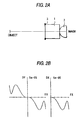
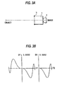
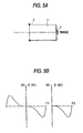
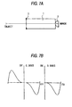
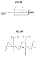
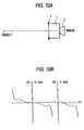
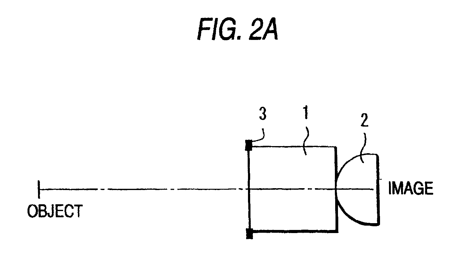
- Figs. 1 - 10 correspond to Examples 1 - 10 and Figs. 11 and 12 correspond to Comparative Examples 1 and 2, respectively.
- Comparative Example 1 is the case of using only a gradient index lens and Comparative Example 2 shows the case where NA on image side has the largest value among all examples of commonly assigned Japanese Patent Application No. 203244/1998.
- block A represents the lens configuration and block B the on-axis aberrations.
- numeral 1 signifies the gradient index lens
- 2 the planoconvex lens
- 3 the aperture diaphragm.
- DY and DX represent lateral aberrations in tangential and sagittal directions, respectively (with r 0 being taken as unity).
- FX and FY represent the distance between the incident light and the optical axis at the diaphragm's position, with the terminal end of each defining the radius of the aperture.
- Tables 2 - 4 show that the value of NA on image side which is 0.629 in Comparative Example 1 and 1.623 in Comparative Example 2 can be increased to about 1.7 and more by adopting the design of the present invention. Particularly high values ( ⁇ 2.1) can be achieved in Examples 2 - 6 and 10.
- the aperture diaphragm is positioned on the object side of the gradient index lens.
- this is not the sole case of the invention which utilizes only the image formed near the optical axis and the aperture diaphragm may be positioned either between the gradient index lens and the planoconvex lens or on the image side of the latter.
- the aperture diaphragm may be a frame part formed integral with the lens holder or some other member.
- the optics of the invention is characterized in that a gradient index lens and a planoconvex lens made of a high-index material are combined in such a way that the convex surface of the latter is directed toward the former.
- the optics used as an objective lens has an adequately increased NA value without suffering from increased aberrations.
- it has a sufficiently small diameter and size to meet the need for realizing high-density recording on optical recording media.
- the optics can be manufactured at low cost.
- a lens is made up of a combination of a single planoconvex lens having a homogeneous refractive index and a single gradient index lens having a gradient refractive index in a radial direction thereof, in which:
Landscapes
- Physics & Mathematics (AREA)
- Optics & Photonics (AREA)
- General Physics & Mathematics (AREA)
- Lenses (AREA)
Abstract
Description
2.2 < n where n: the refractive index of the planoconvex lens.
n: the refractive index of the planoconvex lens.
If remains the same, a greater value of NA is attained than in air (n = 1), eventually producing a smaller beam spot.
| Name | Refractive index (λ in parenetheses) | Remarks | Source |
| Si | 3.43 (3µm) | a | |
| Diamond | 2.42 (0.6µm) | a | |
| TiO2 | 2.61, 2.90 (0.6µm) | birefringent | a |
| SrTiO3 | 2.40 (0.6µm) | a | |
| ZnS | 2.37 (0.6µm) | a | |
| ZnTe | 3.05 (0.6µm) | a | |
| GaP | 3.35 (0.6µm) | a | |
| GaAS | 3.42 (1µm) | a | |
| InP | 3.37 (0.6µm) | a | |
| InAs | 3.4 (0.6µm) | a | |
| Insb | 3.75 (0.6µm) | a | |
| Ge | 4.102 (2.06µm) | b | |
| GaSb | 3.82 | c | |
| AlP | 3.03 | c | |
| AlAs | 3.18 | c | |
| AlSb | 3.79 | c | |
| a: "Hikarikogaku Handobukku (Handbook of Optical Engineering)", published by Asakura Shoten, 1986, p. 306 ff. | |||
| b: "Oyobunkogaku Handobukku (Handbook of Applied Spectroscopy)", ed. by H. Yoshinaga, published by Asakura Shoten, 1973, p. 250 ff. | |||
| c: "Bishokogaku Handobukku (Handbook of Microoptics)", ed. by the Japan Society of Applied Physics and the Society of Optics of Japan, published by Asakura Shoten, 1995, p. 224. |
| Ex. 1 | Ex. 2 | Ex. 3 | Ex. 4 | |
| Distance from object to gradient index lens | 5.00 | 5.00 | 7.00 | 5.00 |
| Radius of aperture diaphragm | 0.95 | 0.95 | 0.95 | 0.95 |
| Radius of gradient index lens, r0 | 1.000 | 1.000 | 1.000 | 1.000 |
| Radius of curvature on object side of gradient index lens | planar surface | planar surface | planar surface | planar surface |
| On-axis refractive index, n0 | 1.64 | 1.80 | 1.80 | 1.80 |
| Second-order gradient index coefficient, g | 0.400 | 0.388 | 0.388 | 0.388 |
| n0·g·r0 | 0.656 | 0.698 | 0.698 | 0.698 |
| Fourth-order gradient index coefficient, h4 | 0.320 | 0.246 | 0.476 | 0.552 |
| Thickness of gradient index lens | 2.063 | 2.079 | 2.072 | 3.709 |
| Radius of curvature on image side of gradient index lens | planar surface | planar surface | planar surface | planar surface |
| Distance between lenses | 0 | 0 | 0 | 0 |
| Refractive index of planoconvex lens | 3.03 | 3.79 | 2.42 | 4.10 |
| Radius of curvature of planoconvex lens, R | 1.000 | 0.800 | 0.600 | 0.300 |
| Thickness of planoconvex lens | 1.2553 | 0.9731 | 0.8501 | 0.3435 |
| Distance from planoconvex lens to image plane | 0 | 0 | 0 | 0 |
| NA on image side | 1.888 | 2.909 | 2.162 | 3.574 |
| Ex. 5 | Ex. 6 | Ex. 7 | Ex. 8 | |
| Distance from object to gradient index lens | infinity | infinity | 4.00 | 5.00 |
| Radius of aperture diaphragm | 1.00 | 1.00 | 0.885 | 0.91 |
| Radius of gradient index lens, r0 | 1.000 | 1.000 | 1.000 | 1.000 |
| Radius of curvature on object side of gradient index lens | planar surface | 2.000 | planar surface | planar surface |
| On-axis refractive index, n0 | 1.70 | 1.70 | 1.64 | 1.55 |
| Second-order gradient index coefficient, g | 0.388 | 0.350 | 0.300 | 0.300 |
| n0·g·r0 | 0.660 | 0.595 | 0.492 | 0.465 |
| Fourth-order gradient index coefficient, h4 | 0.696 | 0.0857 | 0.630 | 0.650 |
| Thickness of gradient index lens | 3.469 | 1.815 | 5.8463 | 6.054 |
| Radius of curvature on image side of gradient index lens | planar surface | planar surface | planar surface | -2.000 |
| Distance between lenses | 0 | 0 | 0 | 0 |
| Refractive index of planoconvex lens | 3.43 | 3.42 | 3.75 | 3.82 |
| Radius of curvature of planoconvex lens, R | 0.200 | 0.600 | 0.600 | 0.350 |
| Thickness of planoconvex lens | 0.2281 | 0.6303 | 0.600 | 0.3411 |
| Distance from planoconvex lens to image plane | 0 | 0 | 0 | 0 |
| NA on image side | 2.752 | 2.254 | 1.699 | 1.796 |
| Ex. 9 | Ex. 10 | Comp. Ex. 1 | Comp. Ex. 2 | |
| Distance from object to gradient index lens | 5.00 | 6.00 | 5.20 | 6.00 |
| Radius of aperture diaphragm | 0.95 | 0.980 | 0.95 | 0.98 |
| Radius of gradient index lens, r0 | 1.000 | 1.000 | 1.000 | 1.000 |
| Radius of curvature on | 2.00 | planar | planar | planar |
| object side of gradient index lens | surface | surface | surface | |
| On-axis refractive index, n0 | 1.55 | 1.75 | 1.70 | 1.682 |
| Second-order gradient index coefficient, g | 0.300 | 0.514 | 0.400 | 0.440 |
| n0·g·r0 | 0.465 | 0.899 | 0.680 | 0.740 |
| Fourth-order gradient index coefficient, h4 | 0.860 | 0.239 | 0.600 | 0.400 |
| Thickness of gradient index lens | 3.925 | -1.453 | 4.217 | 1.5316 |
| Radius of curvature on image side of gradient index lens | -3.30 | planar surface | planar surface | planar surface |
| Distance between lenses | 0 | 0 | - | 0 |
| Refractive index of planoconvex lens | 3.35 | 3.35 | - | 2.20 |
| Radius of curvature of planoconvex lens, R | 0.400 | 0.550 | - | 0.800 |
| Thickness of planoconvex lens | 0.4188 | 0.6920 | - | 1.1828 |
| Distance from planoconvex lens to | 0 | 0 | 0.235 | 0 |
| image plane | ||||
| NA on image side | 1.8097 | 3.124 | 0.629 | 1.623 |
Claims (9)
- Optics using a gradient index lens comprising the combination of a single gradient index lens having a gradient refractive index in a radial direction thereof and a single planoconvex lens having a homogeneous refractive index,(1) the gradient index lens having a planar or convexospherical lens surface;(2) the planoconvex lens being opposed to the gradient index lens such that its optical axis aligns with the optical axis of the gradient index lens and that it satisfies the following condition:
2.2 < n where n: the refractive index of the planoconvex lens. - The optics according to claim 1, wherein the gradient refractive index of the gradient index lens is expressed asr: the distance from the optical axisn(r): the refractive index at distance r from the optical axisn0: the refractive index on the optical axisr0: the radius of the gradient index lensg: the second order gradient index coefficienth4, h6, h8, ...: a higher order gradient index coefficient;
- The optics according to claim 2, wherein the refractive index n of the planoconvex lens is within the range of 2.2 < n ≤ 4.2, the gradient index lens satisfies 0.45 ≤ n0·g·r0 ≤ 0.70, and the convex surface of the planoconvex lens is spherical and satisfies 0.2r0 ≤ R ≤ 1.0r0, where R is the radius of curvature of the convex surface of the planoconvex lens.
- Objective lens optics according to claim 1, which is built in an optical head in such a way that one of the two lens surfaces of the gradient index lens is opposed to the convex surface of the planoconvex lens, that the other lens surface of the gradient index lens is opposed to a light source and that the planar surface of the planoconvex lens is opposed to a recording medium.
- Objective lens optics according to claim 2, which is built in an optical head in such a way that one of the two lens surfaces of the gradient index lens is opposed to the convex surface of the planoconvex lens, that the other lens surface of the gradient index lens is opposed to a light source and that the planar surface of the planoconvex lens is opposed to a recording medium.
- Objective lens optics according to claim 3, which is built in an optical head in such a way that one of the two lens surfaces of the gradient index lens is opposed to the convex surface of the planoconvex lens, that the other lens surface of the gradient index lens is opposed to a light source and that the planar surface of the planoconvex lens is opposed to a recording medium.
- Objective lens optics according to claim 4, wherein focal position on the image side substantially coincides with the planar surface of the planoconvex lens.
- Objective lens optics according to claim 5, wherein focal position on the image side substantially coincides with the planar surface of the planoconvex lens.
- Objective lens optics according to claim 6, wherein focal position on the image side substantially coincides with the planar surface of the planoconvex lens.
Applications Claiming Priority (2)
| Application Number | Priority Date | Filing Date | Title |
|---|---|---|---|
| JP7539399 | 1999-03-19 | ||
| JP11075393A JP2000266996A (en) | 1999-03-19 | 1999-03-19 | Optical system using gradient index lens |
Publications (2)
| Publication Number | Publication Date |
|---|---|
| EP1039315A2 true EP1039315A2 (en) | 2000-09-27 |
| EP1039315A3 EP1039315A3 (en) | 2001-02-28 |
Family
ID=13574912
Family Applications (1)
| Application Number | Title | Priority Date | Filing Date |
|---|---|---|---|
| EP00104453A Withdrawn EP1039315A3 (en) | 1999-03-19 | 2000-03-06 | Optics using a gradient index lens |
Country Status (3)
| Country | Link |
|---|---|
| US (1) | US6330116B1 (en) |
| EP (1) | EP1039315A3 (en) |
| JP (1) | JP2000266996A (en) |
Cited By (1)
| Publication number | Priority date | Publication date | Assignee | Title |
|---|---|---|---|---|
| WO2005124398A1 (en) | 2004-06-22 | 2005-12-29 | Nippon Telegraph And Telephone Corporation | Optical material, optical lens and prism |
Families Citing this family (3)
| Publication number | Priority date | Publication date | Assignee | Title |
|---|---|---|---|---|
| JP4864509B2 (en) * | 2006-03-31 | 2012-02-01 | 株式会社沖データ | Lens array, exposure apparatus, and image forming apparatus |
| DE102006046555B4 (en) * | 2006-09-28 | 2010-12-16 | Grintech Gmbh | Miniaturized optical imaging system with high lateral and axial resolution |
| CN111562715A (en) * | 2020-05-25 | 2020-08-21 | 深圳市点睛创视技术有限公司 | Composite collimating device and system for micro projection |
Family Cites Families (5)
| Publication number | Priority date | Publication date | Assignee | Title |
|---|---|---|---|---|
| JPS61277913A (en) * | 1985-05-31 | 1986-12-08 | Canon Inc | Image forming lens |
| JPH0823625B2 (en) * | 1985-07-25 | 1996-03-06 | オリンパス光学工業株式会社 | Image transmission optical system using inhomogeneous lens |
| US5619488A (en) * | 1991-09-07 | 1997-04-08 | Fuji Xerox Co., Ltd. | Information recording device |
| JP3548331B2 (en) * | 1996-04-15 | 2004-07-28 | オリンパス株式会社 | Lens system |
| JPH11149038A (en) * | 1997-09-12 | 1999-06-02 | Nippon Sheet Glass Co Ltd | Optical system using gradient index lens |
-
1999
- 1999-03-19 JP JP11075393A patent/JP2000266996A/en active Pending
-
2000
- 2000-03-06 EP EP00104453A patent/EP1039315A3/en not_active Withdrawn
- 2000-03-15 US US09/525,519 patent/US6330116B1/en not_active Expired - Fee Related
Cited By (3)
| Publication number | Priority date | Publication date | Assignee | Title |
|---|---|---|---|---|
| WO2005124398A1 (en) | 2004-06-22 | 2005-12-29 | Nippon Telegraph And Telephone Corporation | Optical material, optical lens and prism |
| EP1760496A4 (en) * | 2004-06-22 | 2008-04-02 | Nippon Telegraph & Telephone | OPTICAL MATERIAL, OPTICAL LENS AND PRISM |
| US7674737B2 (en) | 2004-06-22 | 2010-03-09 | Nippon Telegraph And Telephone Corporation | Optical medium, an optical lens and a prism |
Also Published As
| Publication number | Publication date |
|---|---|
| EP1039315A3 (en) | 2001-02-28 |
| JP2000266996A (en) | 2000-09-29 |
| US6330116B1 (en) | 2001-12-11 |
Similar Documents
| Publication | Publication Date | Title |
|---|---|---|
| JP3932578B2 (en) | Objective lens and optical pickup device | |
| US5157555A (en) | Apparatus for adjustable correction of spherical aberration | |
| JP3608333B2 (en) | Optical pickup and method of assembling objective lens for optical pickup | |
| JPH10208276A (en) | Optical pickup device | |
| EP1184855A2 (en) | Objective lens for optical recording media and optical pickup apparatus using the same | |
| US4768867A (en) | Aspherical single lens | |
| US5835473A (en) | Optical pick-up, optical data recording apparatus and objective lens for optical data recording material | |
| US6330116B1 (en) | Optics using a gradient index lens | |
| US5161063A (en) | Objectives for an optical data storage head | |
| JPS60120310A (en) | Aspheric single lens | |
| US6078431A (en) | Object lens system | |
| JP3918331B2 (en) | Reflective micro-optical system | |
| EP1168311B1 (en) | Objective lens, optical pickup device and optical recording/reproducing apparatus | |
| FR2576112A1 (en) | SYSTEM WITH A SINGLE LENS WITH PROGRESSIVE REFRACTIVE INDEX | |
| JPS61189512A (en) | Aspherical single lens | |
| US4668055A (en) | Lens for an optical recording/reproducing apparatus and optical recording/reproducing apparatus using same | |
| US4065205A (en) | Short focal length optical system with large aperture | |
| JP4364328B2 (en) | Objective lens for high-density optical recording media | |
| EP0156453B1 (en) | Lens for an optical recording/reproducing apparatus | |
| JPH11149038A (en) | Optical system using gradient index lens | |
| US20020027863A1 (en) | Complex objective lens and method for manufacturing the same and optical pickup device and optical recording/reproducing apparatus | |
| JP3014311B2 (en) | Objective lens system with variable disk substrate thickness | |
| JPH02150816A (en) | Aspheric single lens | |
| JPH11202194A (en) | High numerical aperture optical system and optical information recording / reproducing apparatus using the same | |
| JP2622155B2 (en) | Aspheric single lens |
Legal Events
| Date | Code | Title | Description |
|---|---|---|---|
| PUAI | Public reference made under article 153(3) epc to a published international application that has entered the european phase |
Free format text: ORIGINAL CODE: 0009012 |
|
| AK | Designated contracting states |
Kind code of ref document: A2 Designated state(s): DE FR GB |
|
| AX | Request for extension of the european patent |
Free format text: AL;LT;LV;MK;RO;SI |
|
| PUAL | Search report despatched |
Free format text: ORIGINAL CODE: 0009013 |
|
| AK | Designated contracting states |
Kind code of ref document: A3 Designated state(s): AT BE CH CY DE DK ES FI FR GB GR IE IT LI LU MC NL PT SE |
|
| AX | Request for extension of the european patent |
Free format text: AL;LT;LV;MK;RO;SI |
|
| RIC1 | Information provided on ipc code assigned before grant |
Free format text: 7G 02B 3/00 A, 7G 11B 7/135 B, 7G 11B 7/125 B |
|
| 17P | Request for examination filed |
Effective date: 20010607 |
|
| AKX | Designation fees paid |
Free format text: DE FR GB |
|
| 17Q | First examination report despatched |
Effective date: 20040319 |
|
| STAA | Information on the status of an ep patent application or granted ep patent |
Free format text: STATUS: THE APPLICATION IS DEEMED TO BE WITHDRAWN |
|
| 18D | Application deemed to be withdrawn |
Effective date: 20040730 |