EP1039159A2 - Magnetic suspending device controlled by temperature of controlled object - Google Patents
Magnetic suspending device controlled by temperature of controlled object Download PDFInfo
- Publication number
- EP1039159A2 EP1039159A2 EP00104557A EP00104557A EP1039159A2 EP 1039159 A2 EP1039159 A2 EP 1039159A2 EP 00104557 A EP00104557 A EP 00104557A EP 00104557 A EP00104557 A EP 00104557A EP 1039159 A2 EP1039159 A2 EP 1039159A2
- Authority
- EP
- European Patent Office
- Prior art keywords
- controlled object
- temperature
- position displacement
- displacement detection
- detection sensors
- Prior art date
- Legal status (The legal status is an assumption and is not a legal conclusion. Google has not performed a legal analysis and makes no representation as to the accuracy of the status listed.)
- Granted
Links
Images



Classifications
-
- F—MECHANICAL ENGINEERING; LIGHTING; HEATING; WEAPONS; BLASTING
- F16—ENGINEERING ELEMENTS AND UNITS; GENERAL MEASURES FOR PRODUCING AND MAINTAINING EFFECTIVE FUNCTIONING OF MACHINES OR INSTALLATIONS; THERMAL INSULATION IN GENERAL
- F16C—SHAFTS; FLEXIBLE SHAFTS; ELEMENTS OR CRANKSHAFT MECHANISMS; ROTARY BODIES OTHER THAN GEARING ELEMENTS; BEARINGS
- F16C32/00—Bearings not otherwise provided for
- F16C32/04—Bearings not otherwise provided for using magnetic or electric supporting means
- F16C32/0406—Magnetic bearings
- F16C32/044—Active magnetic bearings
- F16C32/0444—Details of devices to control the actuation of the electromagnets
- F16C32/0451—Details of controllers, i.e. the units determining the power to be supplied, e.g. comparing elements, feedback arrangements with P.I.D. control
-
- F—MECHANICAL ENGINEERING; LIGHTING; HEATING; WEAPONS; BLASTING
- F16—ENGINEERING ELEMENTS AND UNITS; GENERAL MEASURES FOR PRODUCING AND MAINTAINING EFFECTIVE FUNCTIONING OF MACHINES OR INSTALLATIONS; THERMAL INSULATION IN GENERAL
- F16C—SHAFTS; FLEXIBLE SHAFTS; ELEMENTS OR CRANKSHAFT MECHANISMS; ROTARY BODIES OTHER THAN GEARING ELEMENTS; BEARINGS
- F16C32/00—Bearings not otherwise provided for
- F16C32/04—Bearings not otherwise provided for using magnetic or electric supporting means
-
- F—MECHANICAL ENGINEERING; LIGHTING; HEATING; WEAPONS; BLASTING
- F16—ENGINEERING ELEMENTS AND UNITS; GENERAL MEASURES FOR PRODUCING AND MAINTAINING EFFECTIVE FUNCTIONING OF MACHINES OR INSTALLATIONS; THERMAL INSULATION IN GENERAL
- F16C—SHAFTS; FLEXIBLE SHAFTS; ELEMENTS OR CRANKSHAFT MECHANISMS; ROTARY BODIES OTHER THAN GEARING ELEMENTS; BEARINGS
- F16C32/00—Bearings not otherwise provided for
- F16C32/04—Bearings not otherwise provided for using magnetic or electric supporting means
- F16C32/0406—Magnetic bearings
- F16C32/044—Active magnetic bearings
- F16C32/0444—Details of devices to control the actuation of the electromagnets
- F16C32/0446—Determination of the actual position of the moving member, e.g. details of sensors
-
- H—ELECTRICITY
- H02—GENERATION; CONVERSION OR DISTRIBUTION OF ELECTRIC POWER
- H02N—ELECTRIC MACHINES NOT OTHERWISE PROVIDED FOR
- H02N15/00—Holding or levitation devices using magnetic attraction or repulsion, not otherwise provided for
Definitions
- the present invention relates to a magnetic suspending device for magnetically suspending a magnetizable controlled object without contact at an arbitrary position by making use of magnetic attractive or repulsive forces generated by electromagnets.
- Fig. 1 is a schematic diagram showing the construction of a magnetic suspending device of this type
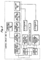
- Fig. 2 is a circuit diagram showing the construction of a control device for controlling the magnetic suspension and support of the magnetic suspending device.
- the magnetic suspending device comprises a pair of electromagnets 11, 13 disposed opposite to each other, a magnetizable controlled object 15 disposed between the pair of electromagnets and position displacement detection sensors 12, 14 disposed opposite to each other for detecting a position displacement of the controlled object 15.
- Detection signals from the position displacement detection sensors 12, 14 are inputted into a control circuit unit 20 for performing phase compensation and gain adjustment, and magnetic attractive or repulsive forces generated by the pair of electromagnets 11, 13 are controlled by control outputs from the control circuit unit 20 so as to suspend the controlled object 15 without contact at an arbitrary position between the pair of electromagnets 11, 13.
- the control circuit unit 20 comprises load resistors 21, 22, a sensor signal processing circuit unit 23, an offset adjusting circuit unit 24, a phase compensating circuit unit 25, a gain adjusting circuit unit 26, a main amplifier unit 27 and a threshold outputting unit 28. Detection signals from the position displacement detection sensors 12, 14 are directed to the phase compensating circuit unit 25 and the gain adjusting circuit unit 26 for phase compensation and gain adjustment through the load resistors 21, 22, the sensor signal processing circuit unit 23 and the offset adjusting circuit unit 24, and the signals so compensated and adjusted are then fed back to the electromagnets 11, 13 through the main amplifier unit 27.
- control circuit unit examples include Japanese Patent Publication No. Sho 61-37643 and Japanese Patent Laid-open No. Hei 9-257035, and those documents are expressly incorporated herein by reference in its entirety.
- the controlled object 15 magnetically suspended by magnetic attractive or repulsive forces generated by the pair of electromagnets 11, 13 receives strong electromagnetic forces from the electromagnets 11, 13 or rotational driving electromagnets (not shown) at any time while being magnetically suspended.
- the above described magnetic suspending device is used, for example, as a magnetic bearing device, in this case, it is difficult to dissipate heat from the controlled object 15 and/or cool the object 15 by virtue of heat conduction, because the construction of the magnetic suspending device allows the secondary loss heat, generated in the controlled object 15, to be generated only in a state in which the controlled object 15 is held without contact.
- the controlled object 15 can be cooled only to a very small extent by virtue of heat conduction. Therefore, if the controlled object 15 is heated abnormally by being run for a long time or by radiation heat received from the surrounding environment of the magnetic bearing device, it is difficult to dissipate heat to the outside of the device.
- the temperature of the controlled object 15 goes up abnormally, it will cause materials (such as metal) deformation and/or brittle fracture of respective constituent components of the controlled object 15, resulting in a failure fatal to the device.
- a protective means has been developed in which the magnetic suspending device is operated, by measuring and monitoring the temperature of the controlled object 15, within a range of temperature where the respective constituent components of the controlled object 15 can safely be used.
- a protective means has been used to measure the temperature of the controlled object by means of an optical means such as a radiation thermometer so as to stop the operation of the control device of the magnetic suspending device when a measured temperature becomes equal to or higher than a predetermined temperature.
- the temperature of the controlled object 15 when the temperature of the controlled object 15 is measured by a radiation thermometer, the temperature needs to be measured directly by detecting infrared radiation emitted from the controlled object 15.
- the controlled object 15 is used in a vacuum or gaseous atmosphere and hence needs to be isolated from the outside, it is necessary to provide a measuring window in the magnetic suspending device for transmission of infrared radiation emitted from the controlled object 15 or to arrange for the infrared radiation to reach a radiation temperature measuring unit through the interior of the magnetic suspending device via a predetermined path without leaking from the device to the outside.
- the magnetic suspending device needs to be specially worked or structured, for example, such that an infrared radiation extraction path using optical fibers is provided, thus causing such a problem as troublesome production process and increase in costs.
- the temperature of the controlled object 15 is measured using any optical technique, if a change in transmittance of infrared radiation due to a smudge on the measuring window or deterioration with age of the optical fibers occurs in a path which transmits the infrared radiation and which runs up to a detection part of the radiation thermometer provided outside the magnetic suspending device, the temperature of the controlled object cannot be measured accurately, and this requires maintenance work including readjustment of the radiation thermometer and replacement of a part of the radiation transmission path.
- the present invention has been proposed in view of the aforesaid drawbacks of the prior art, and an object of the present invention is to provide a magnetic suspending device which can detect the temperature of a controlled object and assure a safe operation of the suspension device without any need for special construction of the magnetic suspension device, special work done thereto and special maintenance therefor.
- a magnetic suspending device comprising:
- the temperature calculation circuit detects the temperature of the controlled object using the outputs from the position displacement detection sensors.
- the temperature calculation circuit is provided for detecting the temperature of the controlled object using the detection signals outputted from the position displacement detection sensors, it is possible to detect the temperature of the controlled object at any time and to assure a safe operation of the device without any need for special construction thereof, special work thereto and special maintenance therefor.
- the invention described in claim 2 provides a magnetic suspending device as set forth in claim 1, wherein the temperature calculation circuit is provided as a displacement detection circuit system separate from a magnetic suspension control system operative to perform processing in the control circuit, said temperature calculation circuit operable to detect the size of the gaps between the controlled object and the position displacement detection sensors without giving any influence to the magnetic suspension control system, thereby detecting the temperature of the controlled object using a change in size of the gaps.
- the temperature calculation circuit is provided as the displacement detection circuit system separate from the magnetic suspension control system operative to perform processing in the control circuit, it is possible that the temperature of the controlled object can be detected without giving any influence to the magnetic suspension control system by causing the outputs from the position displacement detection sensors to be shunted and inputted into the temperature calculation circuit.
- the invention described in claim 3 provides a magnetic suspending device as set forth in claim 1 or 2, further comprising a protection circuit for giving an alarm to the outside and/or for stopping the operation of the magnetic suspending device if the temperature of the controlled object detected by the temperature calculation circuit becomes equal to or higher than a predetermined temperature.
- the protection circuit constructed as described above makes it possible to give an alarm to the outside and/or to stop the operation of the magnetic suspending device before materials deformation and/or brittle fracture of the respective constituent components of the controlled object occur if the temperature of the controlled object goes up abnormally, and, therefore, it is possible to remove any cause of a failure fatal to the device.
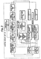
- FIG. 3 shows the construction of a control device of a magnetic suspending device according to the present invention.
- the control circuit unit of the magnetic suspending device according to the present invention is identical to that shown in Fig.
- a controlled object 15 is magnetically suspended without contact at an arbitrary position between a pair of electromagnets 11, 13 by allowing detection signals from position displacement detection sensors 12, 14 to be inputted to a control circuit unit 20 for performing phase compensation and gain adjustment and by controlling magnetic attractive or repulsive forces generated by the pair of electromagnets 11, 13 by control outputs from the control circuit unit 20.
- the control device shown in Fig. 3 is different from the control circuit unit shown in Fig. 2 in that a temperature calculation circuit unit 30 is provided, whereby the detection signals from the position displacement detection sensors 12, 14 are shunted so as to be led to the temperature calculation circuit unit 30 for the purpose of detecting the temperature of the controlled object 15 without contact and that a protection circuit unit 70 is provided for giving an alarm to the outside and stopping a magnetic suspension control if the temperature of the controlled object 15 detected by the temperature calculation circuit unit 30 becomes equal to or higher than a predetermined temperature value.
- the temperature calculation circuit unit 30 comprises preamplifiers 31, 32 and a signal processing unit 33.
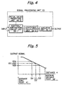
- the signal processing unit 33 comprises, as shown in Fig. 4, an addition/subtraction circuit unit 33-1, a coefficient calculation unit 33-2, an initial value presetting unit 33-3 and an amplifier unit 33-4.
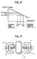
- the position displacement detection sensors 12, 14 are in general disposed opposite to each other at both sides of the controlled object 15, and a combination of detection signals detected by the respective position displacement detection sensors 12, 14 represents a detection characteristic. Paying attention to the respective detection signals from the pair of position displacement detection sensors 12, 14 disposed opposite to each other, it is understood that the respective position displacement detection sensors 12, 14 detect distances between the controlled object 15 and the sensors on the basis of such characteristics as shown in Fig. 5.
- the axis of abscissa indicates a distance L between the controlled object 15 and one of the position displacement detection sensors 12, 14, while the axis of ordinates indicates output signals from the position displacement detection sensors 12, 14.
- the controlled object 15 is controlled at any time such as to be positioned at the center of the position displacement detection sensors disposed opposite to each other. As a result, as shown in Fig. 6, distances D1, D2 from the respective position displacement detection sensors 12, 14 to the controlled object 15 become substantially equal. If the controlled object 15 is movable, as shown in Fig.
- distances D3, D4 from the respective position displacement detection sensors 12, 14 to the controlled object 15 are determined so that the controlled object 15 is at a position where a load applied to the controlled object 15 equilibrates the magnetic attractive or repulsive forces exerted from the electromagnets 11, 13.
- a change in temperature appearing in the controlled object 15 results in a change in the size of the gaps between the position displacement detection sensors 12, 14 and the controlled object 15, and therefore, a sum of the outputs from the position displacement detection sensors 12, 14 changes.
- the temperature calculation circuit unit 30 is provided in the control device separately from the control circuit unit 20 which performs control of magnetic suspension, as shown in Fig. 3.
- a signal processing unit 33 of the temperature calculation circuit unit 30 is constructed such as shown in Fig. 4.
- the respective outputs VD3, VD4 of the position displacement detection sensors 12, 14 are added to obtain (VD3 + VD4) by the addition/subtraction circuit unit 33-1, as shown in the equation (1), and a predetermined initial value (VD1 + VD2) preset in the initial value presetting unit 33-3 is subtracted from the added value to compute a value of change in size of the gaps.
- the rate of expansion found in the controlled object 15 is calculated from the value of change in size of the gaps obtained by the addition/subtraction circuit unit 33-1. Further, based on a value of change in temperature of the components determined by the calculated rate of expansion, a value of change in temperature of the controlled object 15 is calculated by the coefficient calculation unit 33-2, as shown in Fig. 11. It is noted that, in Fig. 11, the axis of abscissas indicates the rate of expansion, while the axis of ordinates indicates the temperature of the materials forming the controlled object 15.
- the protection circuit unit 70 uses the value of change in temperature calculated by the coefficient calculation unit 33-2 to output an alarm and indication signal given to the outside of the magnetic suspension device for urging maintenance or a signal for stopping suspension control itself of the magnetic suspending device in a case where it is detected that a predetermined temperature has been reached at which serious damages are expected to be caused to the magnetic suspending device in view of the characteristics of the materials of the mechanical components constituting the controlled object 15.
Landscapes
- Engineering & Computer Science (AREA)
- General Engineering & Computer Science (AREA)
- Mechanical Engineering (AREA)
- Physics & Mathematics (AREA)
- Electromagnetism (AREA)
- Chemical & Material Sciences (AREA)
- Combustion & Propulsion (AREA)
- Control Of Position Or Direction (AREA)
- Magnetic Bearings And Hydrostatic Bearings (AREA)
Abstract
Description
Claims (3)
- A magnetic suspending device comprising:a pair of electromagnets disposed opposite to each other;a magnetizable controlled object disposed between said pair of electromagnets;position displacement detection sensors disposed opposite to each other for detecting a position displacement of said controlled object;a control device for controlling magnetic forces generated by said pair of electromagnets so as to magnetically suspend said controlled object without contact in accordance with detection signals outputted from said position displacement detection sensors; anda temperature calculation circuit for detecting a change in size of said control object on the basis of the detection signals from said position displacement detection sensors, thereby detecting the temperature of said controlled object.
- A magnetic suspending device as set forth in Claim 1, wherein said temperature calculation circuit is provided as a displacement detection circuit system separate from a magnetic suspension control system including said control circuit, said temperature calculation circuit operable to detect the size of gaps existing between said controlled object and said position displacement detection sensors without giving any influence to said magnetic suspension control system, thereby detecting the temperature of said controlled object on the basis of a change in the size of the gaps and the rate of expansion of said controlled object.
- A magnetic suspending device as set forth in Claim 1 or 2, further comprising a protection circuit for giving an alarm to the outside and/or for stopping the operation of said magnetic suspending device when the temperature of said controlled object detected by said temperature calculation circuit become equal to or higher than a predetermined temperature.
Applications Claiming Priority (2)
| Application Number | Priority Date | Filing Date | Title |
|---|---|---|---|
| JP6498999 | 1999-03-11 | ||
| JP06498999A JP3782606B2 (en) | 1999-03-11 | 1999-03-11 | Magnetic levitation device |
Publications (3)
| Publication Number | Publication Date |
|---|---|
| EP1039159A2 true EP1039159A2 (en) | 2000-09-27 |
| EP1039159A3 EP1039159A3 (en) | 2001-04-18 |
| EP1039159B1 EP1039159B1 (en) | 2002-10-23 |
Family
ID=13273984
Family Applications (1)
| Application Number | Title | Priority Date | Filing Date |
|---|---|---|---|
| EP00104557A Expired - Lifetime EP1039159B1 (en) | 1999-03-11 | 2000-03-13 | Magnetic suspending device controlled by temperature of controlled object |
Country Status (6)
| Country | Link |
|---|---|
| US (1) | US6307294B1 (en) |
| EP (1) | EP1039159B1 (en) |
| JP (1) | JP3782606B2 (en) |
| KR (1) | KR100718739B1 (en) |
| DE (1) | DE60000627T2 (en) |
| TW (1) | TW483993B (en) |
Cited By (1)
| Publication number | Priority date | Publication date | Assignee | Title |
|---|---|---|---|---|
| CN110415589A (en) * | 2019-07-19 | 2019-11-05 | 江苏理工学院 | A kind of magentic suspension demonstrating instrument and its modeling method |
Families Citing this family (11)
| Publication number | Priority date | Publication date | Assignee | Title |
|---|---|---|---|---|
| JP3782606B2 (en) * | 1999-03-11 | 2006-06-07 | 株式会社荏原製作所 | Magnetic levitation device |
| JP3978982B2 (en) * | 2000-06-28 | 2007-09-19 | 株式会社ジェイテクト | Magnetic bearing control device |
| JP2002199655A (en) * | 2000-12-27 | 2002-07-12 | Ishikawajima Harima Heavy Ind Co Ltd | High speed motor |
| JP4509053B2 (en) * | 2006-03-20 | 2010-07-21 | 東芝エレベータ株式会社 | Magnetic levitation device |
| DE102009038775B4 (en) * | 2009-08-25 | 2011-09-01 | Siemens Aktiengesellschaft | Control device and method for controlling a magnetic bearing |
| KR101103504B1 (en) | 2009-10-30 | 2012-01-10 | 한국전력공사 | Axial Magnetic Bearing Device |
| JP2013123297A (en) * | 2011-12-09 | 2013-06-20 | Sega Corp | Magnetic levitation device |
| ITMI20112385A1 (en) * | 2011-12-23 | 2013-06-24 | Wilic Sarl | WIND TURBINE AND METHOD OF CONTROL OF A WIND TURBINE |
| KR102149769B1 (en) * | 2019-01-11 | 2020-08-31 | 권기형 | Hair cutting scissors with multiple blades with deviations by electromagnet |
| US11451169B2 (en) * | 2019-11-25 | 2022-09-20 | Remanence Technology Group, Llc | Multi-dimensional magnetic levitation and translation system and methods |
| CN112211908B (en) * | 2020-10-10 | 2022-04-05 | 珠海格力电器股份有限公司 | Current control method, device and system for magnetic bearing |
Family Cites Families (19)
| Publication number | Priority date | Publication date | Assignee | Title |
|---|---|---|---|---|
| US4180946A (en) | 1975-10-02 | 1980-01-01 | Maurice Brunet | Tool holding spindle assembly particularly for a grinding machine |
| FR2417797A1 (en) * | 1978-02-20 | 1979-09-14 | Europ Propulsion | GRAIN COMPENSATION DEVICE OF A CURRENT FEEDBACK SLAVE CIRCUIT |
| US4652820A (en) * | 1983-03-23 | 1987-03-24 | North American Philips Corporation | Combined position sensor and magnetic motor or bearing |
| JPS61201921A (en) | 1985-03-06 | 1986-09-06 | Hitachi Ltd | magnetic bearing control device |
| JPH0834711B2 (en) * | 1990-08-18 | 1996-03-29 | 日本ビクター株式会社 | Method of detecting rotor stop position in brushless DC motor without position detector |
| US5444369A (en) * | 1993-02-18 | 1995-08-22 | Kearney-National, Inc. | Magnetic rotational position sensor with improved output linearity |
| JP3135410B2 (en) * | 1993-04-14 | 2001-02-13 | 光洋精工株式会社 | Magnetic bearing device |
| US5696412A (en) * | 1993-10-20 | 1997-12-09 | Iannello; Victor | Sensor-less position detector for an active magnetic bearing |
| JPH07139546A (en) * | 1993-11-17 | 1995-05-30 | Ebara Corp | Magnetic bearing device |
| JP3296074B2 (en) * | 1994-03-18 | 2002-06-24 | 株式会社日立製作所 | High-speed rotating body and control device of magnetic bearing used for it |
| US5736800A (en) * | 1994-10-18 | 1998-04-07 | Iannello; Victor | Light weight, high performance radial actuator for magnetic bearing systems |
| JPH08159157A (en) | 1994-12-05 | 1996-06-18 | Seiko Seiki Co Ltd | Magnetic bearing device |
| US5640472A (en) | 1995-06-07 | 1997-06-17 | United Technologies Corporation | Fiber optic sensor for magnetic bearings |
| JP3563167B2 (en) * | 1995-08-31 | 2004-09-08 | セイコーインスツルメンツ株式会社 | Magnetic bearing device |
| JP3591111B2 (en) * | 1996-02-29 | 2004-11-17 | 松下電器産業株式会社 | Magnetic bearing control device |
| JPH09257035A (en) * | 1996-03-22 | 1997-09-30 | Ebara Corp | Magnetic bearing control device |
| KR19980044111U (en) * | 1996-12-26 | 1998-09-25 | 박병재 | Magnetic Levitation Bearings |
| JP3782606B2 (en) * | 1999-03-11 | 2006-06-07 | 株式会社荏原製作所 | Magnetic levitation device |
| KR20190000098A (en) * | 2017-06-22 | 2019-01-02 | 주식회사 렛츠 | The manufacturing method of natural petal cosmetic water composition to have natural petal |
-
1999
- 1999-03-11 JP JP06498999A patent/JP3782606B2/en not_active Expired - Fee Related
-
2000
- 2000-03-09 US US09/522,471 patent/US6307294B1/en not_active Expired - Lifetime
- 2000-03-10 KR KR1020000011962A patent/KR100718739B1/en not_active Expired - Fee Related
- 2000-03-10 TW TW089104320A patent/TW483993B/en not_active IP Right Cessation
- 2000-03-13 EP EP00104557A patent/EP1039159B1/en not_active Expired - Lifetime
- 2000-03-13 DE DE60000627T patent/DE60000627T2/en not_active Expired - Fee Related
Cited By (1)
| Publication number | Priority date | Publication date | Assignee | Title |
|---|---|---|---|---|
| CN110415589A (en) * | 2019-07-19 | 2019-11-05 | 江苏理工学院 | A kind of magentic suspension demonstrating instrument and its modeling method |
Also Published As
| Publication number | Publication date |
|---|---|
| JP2000262079A (en) | 2000-09-22 |
| EP1039159B1 (en) | 2002-10-23 |
| JP3782606B2 (en) | 2006-06-07 |
| EP1039159A3 (en) | 2001-04-18 |
| TW483993B (en) | 2002-04-21 |
| KR100718739B1 (en) | 2007-05-15 |
| DE60000627T2 (en) | 2003-07-03 |
| DE60000627D1 (en) | 2002-11-28 |
| US6307294B1 (en) | 2001-10-23 |
| KR20010006768A (en) | 2001-01-26 |
Similar Documents
| Publication | Publication Date | Title |
|---|---|---|
| EP1039159B1 (en) | Magnetic suspending device controlled by temperature of controlled object | |
| EP0160359B1 (en) | Tuyere pyrometer | |
| EP0967394A1 (en) | Turbo molecular pump | |
| EP0911928A3 (en) | Control method and apparatus for stabilising optical wavelength | |
| US20100027583A1 (en) | Detector | |
| EP1079122A1 (en) | Magnetic bearing device | |
| JP3845218B2 (en) | Differential heat sensor | |
| JPH03281008A (en) | Generation of heat streak predicting method and temperature sensor roll | |
| JP2000262079A5 (en) | ||
| US4033183A (en) | Horizontal- and vertical-roll force measuring system | |
| EP1176325A2 (en) | Magnetic bearing apparatus | |
| KR100276646B1 (en) | Crane position detection device using magnetic sensor | |
| JP3235524B2 (en) | Casting bulging detection method, bulging determination method, bulging prevention method, and apparatus therefor | |
| Iuchi et al. | New radiation thermometer for near room temperature | |
| EP0333290A1 (en) | Device for monitoring the suction vent duct(s) of a smoke/gas detection system | |
| JP2004069186A (en) | Combustion monitoring device | |
| JPH09288023A (en) | Detection structure for abnormality of tensioning apparatus for overhead wire | |
| JP2645141B2 (en) | Temperature control method | |
| JPH0534402B2 (en) | ||
| WO2026044899A1 (en) | Visual sensing-based high-temperature detection system and method for driving device | |
| JP2888308B2 (en) | Dust detector | |
| JPH07236954A (en) | Method and apparatus for detecting powder shortage in mold mouth | |
| JPH0815041A (en) | Heat mass detector | |
| KR100973891B1 (en) | Strip Position Control in Continuous Annealing Furnace | |
| JP2001221717A (en) | Shaft correcting device for testing equipment |
Legal Events
| Date | Code | Title | Description |
|---|---|---|---|
| PUAI | Public reference made under article 153(3) epc to a published international application that has entered the european phase |
Free format text: ORIGINAL CODE: 0009012 |
|
| AK | Designated contracting states |
Kind code of ref document: A2 Designated state(s): DE FR GB |
|
| AX | Request for extension of the european patent |
Free format text: AL;LT;LV;MK;RO;SI |
|
| PUAL | Search report despatched |
Free format text: ORIGINAL CODE: 0009013 |
|
| AK | Designated contracting states |
Kind code of ref document: A3 Designated state(s): AT BE CH CY DE DK ES FI FR GB GR IE IT LI LU MC NL PT SE |
|
| AX | Request for extension of the european patent |
Free format text: AL;LT;LV;MK;RO;SI |
|
| 17P | Request for examination filed |
Effective date: 20010920 |
|
| AKX | Designation fees paid |
Free format text: DE FR GB |
|
| GRAG | Despatch of communication of intention to grant |
Free format text: ORIGINAL CODE: EPIDOS AGRA |
|
| 17Q | First examination report despatched |
Effective date: 20020301 |
|
| GRAG | Despatch of communication of intention to grant |
Free format text: ORIGINAL CODE: EPIDOS AGRA |
|
| GRAH | Despatch of communication of intention to grant a patent |
Free format text: ORIGINAL CODE: EPIDOS IGRA |
|
| GRAH | Despatch of communication of intention to grant a patent |
Free format text: ORIGINAL CODE: EPIDOS IGRA |
|
| GRAA | (expected) grant |
Free format text: ORIGINAL CODE: 0009210 |
|
| AK | Designated contracting states |
Kind code of ref document: B1 Designated state(s): DE FR GB |
|
| REG | Reference to a national code |
Ref country code: GB Ref legal event code: FG4D |
|
| REF | Corresponds to: |
Ref document number: 60000627 Country of ref document: DE Date of ref document: 20021128 |
|
| ET | Fr: translation filed | ||
| PLBE | No opposition filed within time limit |
Free format text: ORIGINAL CODE: 0009261 |
|
| STAA | Information on the status of an ep patent application or granted ep patent |
Free format text: STATUS: NO OPPOSITION FILED WITHIN TIME LIMIT |
|
| 26N | No opposition filed |
Effective date: 20030724 |
|
| PGFP | Annual fee paid to national office [announced via postgrant information from national office to epo] |
Ref country code: FR Payment date: 20080311 Year of fee payment: 9 |
|
| PGFP | Annual fee paid to national office [announced via postgrant information from national office to epo] |
Ref country code: GB Payment date: 20090311 Year of fee payment: 10 |
|
| PGFP | Annual fee paid to national office [announced via postgrant information from national office to epo] |
Ref country code: DE Payment date: 20090306 Year of fee payment: 10 |
|
| REG | Reference to a national code |
Ref country code: FR Ref legal event code: ST Effective date: 20091130 |
|
| PG25 | Lapsed in a contracting state [announced via postgrant information from national office to epo] |
Ref country code: FR Free format text: LAPSE BECAUSE OF NON-PAYMENT OF DUE FEES Effective date: 20091123 |
|
| GBPC | Gb: european patent ceased through non-payment of renewal fee |
Effective date: 20100313 |
|
| PG25 | Lapsed in a contracting state [announced via postgrant information from national office to epo] |
Ref country code: DE Free format text: LAPSE BECAUSE OF NON-PAYMENT OF DUE FEES Effective date: 20101001 |
|
| PG25 | Lapsed in a contracting state [announced via postgrant information from national office to epo] |
Ref country code: GB Free format text: LAPSE BECAUSE OF NON-PAYMENT OF DUE FEES Effective date: 20100313 |