EP1038847B1 - Device and method for etching glass sheets with acid - Google Patents
Device and method for etching glass sheets with acid Download PDFInfo
- Publication number
- EP1038847B1 EP1038847B1 EP19990830157 EP99830157A EP1038847B1 EP 1038847 B1 EP1038847 B1 EP 1038847B1 EP 19990830157 EP19990830157 EP 19990830157 EP 99830157 A EP99830157 A EP 99830157A EP 1038847 B1 EP1038847 B1 EP 1038847B1
- Authority
- EP
- European Patent Office
- Prior art keywords
- acid
- glass
- sheet
- printing plate
- tank
- Prior art date
- Legal status (The legal status is an assumption and is not a legal conclusion. Google has not performed a legal analysis and makes no representation as to the accuracy of the status listed.)
- Expired - Lifetime
Links
- 239000011521 glass Substances 0.000 title claims description 67
- 239000002253 acid Substances 0.000 title claims description 63
- 238000000034 method Methods 0.000 title claims description 29
- 238000005530 etching Methods 0.000 title claims description 18
- KRHYYFGTRYWZRS-UHFFFAOYSA-N Fluorane Chemical compound F KRHYYFGTRYWZRS-UHFFFAOYSA-N 0.000 claims description 12
- XLYOFNOQVPJJNP-UHFFFAOYSA-N water Substances O XLYOFNOQVPJJNP-UHFFFAOYSA-N 0.000 claims description 9
- 239000011248 coating agent Substances 0.000 claims description 8
- 238000000576 coating method Methods 0.000 claims description 8
- 239000000463 material Substances 0.000 claims description 5
- 239000004033 plastic Substances 0.000 claims description 5
- 238000004891 communication Methods 0.000 claims description 3
- 239000012530 fluid Substances 0.000 claims description 3
- 239000013013 elastic material Substances 0.000 claims description 2
- 230000014759 maintenance of location Effects 0.000 claims description 2
- 238000000151 deposition Methods 0.000 claims 1
- 238000005507 spraying Methods 0.000 claims 1
- 239000008237 rinsing water Substances 0.000 description 6
- 230000000694 effects Effects 0.000 description 3
- 238000005086 pumping Methods 0.000 description 3
- 239000004063 acid-resistant material Substances 0.000 description 2
- 239000007788 liquid Substances 0.000 description 2
- 230000000873 masking effect Effects 0.000 description 2
- 239000002699 waste material Substances 0.000 description 2
- 239000000853 adhesive Substances 0.000 description 1
- 238000004026 adhesive bonding Methods 0.000 description 1
- 230000001070 adhesive effect Effects 0.000 description 1
- 239000007864 aqueous solution Substances 0.000 description 1
- 230000005484 gravity Effects 0.000 description 1
- 230000001788 irregular Effects 0.000 description 1
- 238000012986 modification Methods 0.000 description 1
- 230000004048 modification Effects 0.000 description 1
- 230000002787 reinforcement Effects 0.000 description 1
- 239000000243 solution Substances 0.000 description 1
- 229910001220 stainless steel Inorganic materials 0.000 description 1
- 239000010935 stainless steel Substances 0.000 description 1
- 229920002994 synthetic fiber Polymers 0.000 description 1
- 239000010409 thin film Substances 0.000 description 1
Images


Classifications
-
- B—PERFORMING OPERATIONS; TRANSPORTING
- B44—DECORATIVE ARTS
- B44C—PRODUCING DECORATIVE EFFECTS; MOSAICS; TARSIA WORK; PAPERHANGING
- B44C1/00—Processes, not specifically provided for elsewhere, for producing decorative surface effects
- B44C1/22—Removing surface-material, e.g. by engraving, by etching
- B44C1/227—Removing surface-material, e.g. by engraving, by etching by etching
-
- C—CHEMISTRY; METALLURGY
- C03—GLASS; MINERAL OR SLAG WOOL
- C03C—CHEMICAL COMPOSITION OF GLASSES, GLAZES OR VITREOUS ENAMELS; SURFACE TREATMENT OF GLASS; SURFACE TREATMENT OF FIBRES OR FILAMENTS MADE FROM GLASS, MINERALS OR SLAGS; JOINING GLASS TO GLASS OR OTHER MATERIALS
- C03C15/00—Surface treatment of glass, not in the form of fibres or filaments, by etching
Definitions
- This invention relates to a method for etching glass sheets with acid and to a device for implementing this method.
- this technique consists of an initial masking of the glass surface to be etched with suitably contoured masks.
- the glass surface is then put in contact with the acid, generally a solution of hydrofluoric acid, which chemically and selectively engraves the glass without affecting the masked areas.
- suitable devices for etching are also known, particularly for etching large sized glass sheets which are difficult to handle. These devices load the sheet of glass in a substantially vertical position - which is the preferred position for transportation - onto a suitable flat support which is then moved into a horizontal or slightly slanted position, which is preferred for subsequent etching with acid.
- etching large sheets of glass has a considerable advantage in terms of optimizing process productivity, as these sheets of glass, once suitably etched, can be cut into glass panes of the required size.
- the known methods allow sheets of glass with geometrical designs or patterns to be obtained.
- the state of the art does not enable the glass to be worked with acid so as to give it special aesthetic effects, such as an antique appearance or to produce glass with varying degrees of opacity, that is with shaded contours.
- An additional subject of this invention is a device specifically designed to implement this acid etching method, particularly on large sheets of glass, as claimed in the appended claims.
- the device 1 for etching a sheet of glass with acid comprises a stand 2 on the front portion of which a support 3 for a sheet of glass is hinged.
- This support 3 can thus pivot about a horizontal axis which is parallel to the axis of the stand 2. Consequently, it can assume a substantially vertical position to allow a sheet of glass to be loaded (Figure 1) and a substantially horizontal working position (Figure 2).
- the stand 2 can comprise supporting feet 4.
- the stand 2 comprises a fixed rear structure 5 which extends upwards from the base of the stand, diverging away from the latter.
- the stand is completed by two horizontal side bars 2a, 2b which join the upper part of the stand to the rear structure 5 and which act as reinforcements. Furthermore, these side bars 2a, 2b are supporting points for the support 3 when it is in the working position.
- the rear structure 5 supports an actuator 7 which acts via a piston 8 on the support 3, to the underside of which said piston is hinged.
- a retention frame 6 is hinged to the upper end of the rear structure 5.
- the frame 6 can, as a consequence, assume a raised position ( Figure 1) and a horizontal working position ( Figure 2). In the latter position, as will be described in greater detail below, the frame 6 is in contact with the upper surface of the glass to be worked, with the function of holding it in place.
- the frame 6 consists of a perimetral frame and a plurality of crossing crosspieces 6a, 6b.
- Elastic seals 9, preferably made of rubber or other synthetic material, are arranged on the underside of the frame 6, which is destined to come into contact with the sheet of glass, on the underside of said frame and of said crosspieces.
- elastic seals 10 of the same type are arranged along the entire length of the internal edge of the support 3, on which the sheet of glass is placed, as will be described in greater detail below.
- the rear structure 5 supports a second actuator 11 the piston 12 of which is hinged to the upper side of the frame 6.
- a plurality of removable clamping devices 13 are fixed, such as, for example, manual or pneumatic clamps. These clamping devices 13 are arranged so as to clamp the sheet of glass between the support 3 and the frame 6 during the working process ( Figure 2).
- the shape and dimensions of the support 3 substantially correspond to those of the sheet of glass.
- said sheet of glass will be carefully placed inside the perimetral frame of the support 3 on the seal 10.
- the support 3 is modelled so as to comprise, within its perimetral edge, a tank 14 for the acid.
- the tank 14 is located under the sheet of glass so as to allow contact between the underside of the sheet of glass and the acid.
- the tank 14 has a bottom 14a and perimetral ridged edges 14b.
- this tank is made of acid-resistant material.
- the tank 14 can be made of stainless steel or a suitable plastic material.
- the tank 14 comprises, close to one of its four apexes and preferably near one of the two front apexes, a portion 14' enclosed by ridged edges 14c which contains tubular fittings for supplying and draining the acid and the rinsing water.
- the device comprises a first tubular fitting 15 for letting in the acid and a second tubular fitting 16 for letting in the rinsing water.
- the latter may have a smaller diameter than said first fitting 15.
- the device has a tubular fitting 17 for draining the acid and the rinsing water.
- the tubular fittings 15, 16 and 17 are connected in a leaktight manner to respective pipes 15a, 16a, 17a and 17b.
- the pipe 15a puts the tank 14 in communication with a source of acid, while the pipe 16a puts said tank 14 in communication with a source of water, for example the water mains.
- the device can include pumping devices (not shown in the figure) and respective valve means 18, 19 (schematically shown in figures 4 and 5) to facilitate the flow from said sources of acid and water to the tank 14.
- the tubular fitting 17, is connected by means of a two-way fitting to the pipes 17a for draining the waste acid and 17b for draining the rinsing water.
- valve means 20, 21 (schematically shown in Figures 4 and 5) will have to be provided for alternatively allowing the acid to drain via said pipe 17a and the water to drain via said pipe 17b.
- Said pipes 17a, 17b lead to suitable collection tanks from where the liquids used in the process can be taken and disposed of.
- the pipes 17a, 17b can also be connected to pumping means (not shown in the figure) to facilitate draining of the tank 14.
- Said elastic seals 10 are arranged on the perimetral ridged edges 14a and act as a support for the sheet of glass to be worked.
- a sheet 22 of suitable acid-resistant plastic material is stretched over the tank 14 and covers the entire surface of the tank, with the exception of the delimited portion 14' which contains said tubular fittings.
- the sheet 22 is fastened along the perimetral edges 14b of the tank and along the edges 14c of said delimited portion 14', while the remaining surface is left free to move.
- Corrugations or folds 22', or various types of decorative pattern which, as will be described in greater detail below, will be reproduced on the sheet of glass by means of the treatment with acid, are then made on the upper surface of the sheet 22, which faces the glass sheet, for example by gluing a thin film of acid-resistant plastic material to it.
- a relief pattern can be pre-formed on the sheet 22 itself (for example, according to the high relief or bas-relief method).
- a side duct (not shown in the figure) to release residual air bubbles which tend to accumulate when the tank is filled with acid will be made in the edges 14b of the tank 14, over the fastening point of said sheet 22.
- This release duct is made close to the end opposite on the diagonal to the delimited portion 14' of the tank. Towards the outside, this duct is connected by means of a tube to the waste acid collection tank, directly or via the pipe 17a. This is because, inevitably, as the acid is let in and once the residual air has been eliminated, a little acid seeps out and can thus be collected in said tank.
- the release duct can also be used, by means of suitable valve fittings, to let in compressed air in order to accelerate the drainage of the rinsing water.
- a duct 23 is located on the bottom 14a of the tank 14, under the sheet 22, and is connected to a two-way tubular fitting 24 which lets compressed air (or other suitable inert fluid) in and out.
- Air inlet 25 and outlet 26 pipes are connected to said fitting 24.
- the pipe 25 is connected to a source of compressed air, or other suitable fluid, and includes valve means 27.
- the pipe 26 leads to the outside and includes valve means 28. Additionally, the pipe 26 can be connected to pumping means (not shown in the figure) to facilitate evacuating the air from the tank 14.
- said duct 23 should be located close to the apex of the tank 14 opposite on the diagonal to said delimited portion 14', for reasons which will appear more clearly below.
- the support 3 comprises, at the front outer edge (destined to be located underneath when the support 3 is in a substantially vertical position), two or more projecting brackets 29. Said brackets 29 support the sheet of glass when it is placed on the support 3 during the loading stage.
- the device comprises a control unit 30 which can advantageously be arranged on the fixed rear structure 5 of the stand 2 to control the actuators 7 and 11 and the valves 18, 19, 20, 21, 27 and 28.
- the device 1 is initially in a loading position, in which the support 3 is arranged in a substantially vertical position, while the frame 6 is raised, as shown in Figure 1.
- the corrugations 22' - for example forming a wavy pattern, an irregular pattern or realistic or abstract drawings - will have been formed on the sheet 22 beforehand.
- Said corrugations 22' can be fixed in various ways, normally by means of suitable adhesives.
- a sheet of glass V is then placed on said support 3, carefully positioned on the perimetral seals 10, and supported by the brackets 29.
- the sheet V will be placed so that the side to be etched faces the tank 14.
- the support 3 is taken to a substantially horizontal position by means of the actuator 7 and the frame 6 is lowered on top of it by means of the respective actuator 11.
- the sheet V is then clamped between the seals 10 on the support 3 and the seals 9 on the frame 6.
- the clamping action is supplemented by the clamps 13, which can exert a sufficient holding pressure on the sheet of glass V so as to prevent leakage of acid from the tank 14 during the subsequent working phase ( Figures 2 and 4).
- the support 3 is not actually horizontal but is slightly slanted in the direction of its diagonal so that the delimited portion 14' is in a lower position with respect to the rest of the support. This facilitates draining of the tank 14 at the end of the working phase and additionally allows any residual air bubbles to collect in a corner of the tank and to be removed via the release duct described above as the liquids are loaded into said tank.
- the following phase consists in letting acid into the tank 14 through the tubular fitting 15, at least until the surface of the sheet 22 is totally covered.
- An aqueous solution of hydrofluoric acid is used as the acid, usually in a concentration of approximately 30%. This is because, as is known, hydrofluoric acid easily attacks glass at ambient temperature.
- the next phase of the method entails letting air in through the tubular fitting 23 so as to inflate the sheet 22 until it comes into contact with the surface of the sheet of glass V to be etched ( Figure 5).
- the sheet V is chemically etched by the acid.
- the greater the amount of acid coming into contact with the glass the deeper the etching will be. Consequently, the etching will be shallower along the peaks of said corrugations 22', becoming progressively deeper away from said peaks towards the gaps between the corrugations.
- the resulting effect is to reproduce patterns with shaded contours on the glass.
- the result will be "antique glass” or glass with different degrees of opacity.
- the final result also depends on the time the acid is left in contact with tne surface of the sheet of glass V. This time is generally of the order of approximately 15 minutes, but can obviously be varied according to requirements.
- concentration of the hydrofluoric acid used is Another defining factor. This is because concentrations higher or lower than 30% w/v can be used, suitably balancing the contact times according to the type of working process required.
- the air is drained through the pipe 26, preferably by means of a pump.
- the sheet will then be returned to the rest position, as shown in Figure 4.
- the following phase consists in letting in rinsing water through the tubular fitting 16 to fill the tank 14. After rinsing, the water is drained through the pipe 17b by opening the valve 21. The rinsing operation, if required, can be repeated.
- the sheet is then released by releasing the clamps 13 and taking the support 3 back to its vertical position, as shown in Figure 1.
- the particular feature of the method to which this invention relates and of the aforementioned device specifically designed to implement this method is thus that it allows a sheet of glass to be etched with acid so as to create patterns with shaded contours.
- the known methods allow only patterns with well-defined contours to be obtained. This is because these methods employ a masking of those portions of the glass surface which will not be etched, while the remaining surface comes into contact with the same amount of acid in the same way, thus producing an even etching with clearly defined contours.
- the essential element which distinguishes the method forming the subject of this invention from known methods is, rather, the fact that the sheet of glass is in contact with the surface of a printing plate (a suitably corrugated sheet (22), in the aforesaid example), on which patterns have been made in relief and on which a coating of acid of uneven thickness has been deposited, said coating of acid being thinner along the peaks of said relief patterns and progressively thicker in the recesses of said surface, so that the amount of acid which comes into contact with the surface of the sheet of glass is different from one area to the other of the surface of said sheet.
- a printing plate a suitably corrugated sheet (22), in the aforesaid example
- the amplitude of the shading obtained is also directly proportional to the softness and the elasticity of the material used to reproduce the reliefs on the sheet 22.
- the sheet 22 with the corrugations 22' can be replaced by a stiff or elastic plate 22a, on the upper surface of which, destined to come into contact with the glass surface, relief patterns 22'' are pre-formed (for example, according to the bas-relief or high relief techniques), as shown in Figures 6 and 7.
- said fastening devices may consist of a tape 31 made of acid-resistant plastic, which extends along the entire length of the perimetral edges of the plate 22a and is secured on one side to said edges of the plate and on the other side to the edges 14b, 14c of the tank 14.
- the tape 31 will have a sufficient width to extend as required to allow the plate 22a to come into contact with the sheet of glass V.
- the tape 31 can be made of elastic material.
- Another possible variant of the device forming the subject of this invention consists in positioning the tank of hydrofluoric acid over the tank 14, so as to allow the acid to be loaded into the tank by the force of gravity alone.
Landscapes
- Engineering & Computer Science (AREA)
- Chemical & Material Sciences (AREA)
- Mechanical Engineering (AREA)
- Life Sciences & Earth Sciences (AREA)
- Chemical Kinetics & Catalysis (AREA)
- General Chemical & Material Sciences (AREA)
- Geochemistry & Mineralogy (AREA)
- Materials Engineering (AREA)
- Organic Chemistry (AREA)
- Surface Treatment Of Glass (AREA)
Description
- This invention relates to a method for etching glass sheets with acid and to a device for implementing this method.
- The technique of etching glass sheets with acid to impress the desired patterns thereon is widely known.
- Generally, this technique consists of an initial masking of the glass surface to be etched with suitably contoured masks. The glass surface is then put in contact with the acid, generally a solution of hydrofluoric acid, which chemically and selectively engraves the glass without affecting the masked areas.
- In addition, suitable devices for etching are also known, particularly for etching large sized glass sheets which are difficult to handle. These devices load the sheet of glass in a substantially vertical position - which is the preferred position for transportation - onto a suitable flat support which is then moved into a horizontal or slightly slanted position, which is preferred for subsequent etching with acid.
- It should be noted that etching large sheets of glass has a considerable advantage in terms of optimizing process productivity, as these sheets of glass, once suitably etched, can be cut into glass panes of the required size.
- As mentioned, the known methods allow sheets of glass with geometrical designs or patterns to be obtained. However, the state of the art does not enable the glass to be worked with acid so as to give it special aesthetic effects, such as an antique appearance or to produce glass with varying degrees of opacity, that is with shaded contours.
- The problem which this invention is based on, consequently, is that of obtaining glass with the above characteristics.
- This problem is solved with a method for acid-etching glass as claimed in the appended claims.
- An additional subject of this invention is a device specifically designed to implement this acid etching method, particularly on large sheets of glass, as claimed in the appended claims.
- Additional characteristics and advantages of the method for acid-etching glass and of the device that forms the subject of the present invention will emerge more clearly from the description of an embodiment, given below by way of non-limiting example, with reference to the following figures:
- Figure 1 illustrates a perspective view of the device according to this invention in the position for loading the sheet of glass;
- Figure 2 illustrates a perspective view of the device in Figure 1 in the working position;
- Figure 3 illustrates a schematic plan view from above of the device in Figure 1;
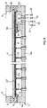
- Figure 4 illustrates a schematic front cross-sectional view of the device according to this invention in a pre-working phase;
- Figure 5 illustrates the view in Figure 4 in the working phase;
- Figure 6 illustrates a schematic front cross-sectional view of the device according to a second form of embodiment of this invention, in a pre-working phase;
- Figure 7 illustrates the view in Figure 6 in the working phase;
- Figure 8 illustrates a schematic front cross-sectional view of the device according to a third form of embodiment of this invention, in the working phase.
-
- The device which is the subject of this invention will now be described with reference to the above figures.
- The device 1 for etching a sheet of glass with acid comprises a stand 2 on the front portion of which a
support 3 for a sheet of glass is hinged. Thissupport 3 can thus pivot about a horizontal axis which is parallel to the axis of the stand 2. Consequently, it can assume a substantially vertical position to allow a sheet of glass to be loaded (Figure 1) and a substantially horizontal working position (Figure 2). - The stand 2 can comprise supporting feet 4.
- In addition, the stand 2 comprises a fixed
rear structure 5 which extends upwards from the base of the stand, diverging away from the latter. The stand is completed by twohorizontal side bars rear structure 5 and which act as reinforcements. Furthermore, theseside bars support 3 when it is in the working position. - The
rear structure 5 supports an actuator 7 which acts via a piston 8 on thesupport 3, to the underside of which said piston is hinged. - A
retention frame 6 is hinged to the upper end of therear structure 5. Theframe 6 can, as a consequence, assume a raised position (Figure 1) and a horizontal working position (Figure 2). In the latter position, as will be described in greater detail below, theframe 6 is in contact with the upper surface of the glass to be worked, with the function of holding it in place. - The
frame 6 consists of a perimetral frame and a plurality of crossingcrosspieces Elastic seals 9, preferably made of rubber or other synthetic material, are arranged on the underside of theframe 6, which is destined to come into contact with the sheet of glass, on the underside of said frame and of said crosspieces. - Similarly,
elastic seals 10 of the same type are arranged along the entire length of the internal edge of thesupport 3, on which the sheet of glass is placed, as will be described in greater detail below. - In addition, the
rear structure 5 supports asecond actuator 11 thepiston 12 of which is hinged to the upper side of theframe 6. - On the
frame 6, along the perimetral frame, a plurality ofremovable clamping devices 13 are fixed, such as, for example, manual or pneumatic clamps. Theseclamping devices 13 are arranged so as to clamp the sheet of glass between thesupport 3 and theframe 6 during the working process (Figure 2). - The shape and dimensions of the
support 3 substantially correspond to those of the sheet of glass. In particular, said sheet of glass will be carefully placed inside the perimetral frame of thesupport 3 on theseal 10. - The
support 3 is modelled so as to comprise, within its perimetral edge, atank 14 for the acid. In practice, once the sheet of glass is placed on theperimetral seal 10, thetank 14 is located under the sheet of glass so as to allow contact between the underside of the sheet of glass and the acid. - The
tank 14 has abottom 14a and perimetralridged edges 14b. - Obviously, this tank, as with all the parts of the device which come into contact with the acid, is made of acid-resistant material. In particular, the
tank 14 can be made of stainless steel or a suitable plastic material. - The
tank 14 comprises, close to one of its four apexes and preferably near one of the two front apexes, a portion 14' enclosed byridged edges 14c which contains tubular fittings for supplying and draining the acid and the rinsing water. - In particular, the device comprises a first
tubular fitting 15 for letting in the acid and a secondtubular fitting 16 for letting in the rinsing water. The latter may have a smaller diameter than said first fitting 15. - Furthermore, the device has a
tubular fitting 17 for draining the acid and the rinsing water. - The
tubular fittings respective pipes - The
pipe 15a puts thetank 14 in communication with a source of acid, while thepipe 16a puts saidtank 14 in communication with a source of water, for example the water mains. Additionally, the device can include pumping devices (not shown in the figure) and respective valve means 18, 19 (schematically shown in figures 4 and 5) to facilitate the flow from said sources of acid and water to thetank 14. - The
tubular fitting 17, on the other hand, is connected by means of a two-way fitting to thepipes 17a for draining the waste acid and 17b for draining the rinsing water. Additionally, valve means 20, 21 (schematically shown in Figures 4 and 5) will have to be provided for alternatively allowing the acid to drain via saidpipe 17a and the water to drain via saidpipe 17b. - Said
pipes pipes tank 14. - It is clear that the pipes which are in contact with the acid must also be made of acid-resistant material.
- Said
elastic seals 10 are arranged on the perimetralridged edges 14a and act as a support for the sheet of glass to be worked. - A
sheet 22 of suitable acid-resistant plastic material is stretched over thetank 14 and covers the entire surface of the tank, with the exception of the delimited portion 14' which contains said tubular fittings. - The
sheet 22 is fastened along theperimetral edges 14b of the tank and along theedges 14c of said delimited portion 14', while the remaining surface is left free to move. Corrugations or folds 22', or various types of decorative pattern which, as will be described in greater detail below, will be reproduced on the sheet of glass by means of the treatment with acid, are then made on the upper surface of thesheet 22, which faces the glass sheet, for example by gluing a thin film of acid-resistant plastic material to it. Alternatively, a relief pattern can be pre-formed on thesheet 22 itself (for example, according to the high relief or bas-relief method). - It is important to note that said
ridged edges perimetral seals 10 which, in turn, are arranged on theedges 14b on top of thesheet 22. Consequently, there is a gap between thesheet 22 and the sheet of glass where the acid is let in, as will be described in greater detail below. - Preferably, a side duct (not shown in the figure) to release residual air bubbles which tend to accumulate when the tank is filled with acid will be made in the
edges 14b of thetank 14, over the fastening point of saidsheet 22. This release duct is made close to the end opposite on the diagonal to the delimited portion 14' of the tank. Towards the outside, this duct is connected by means of a tube to the waste acid collection tank, directly or via thepipe 17a. This is because, inevitably, as the acid is let in and once the residual air has been eliminated, a little acid seeps out and can thus be collected in said tank. The release duct can also be used, by means of suitable valve fittings, to let in compressed air in order to accelerate the drainage of the rinsing water. - It is also clear that there is a gap between the underside of the
sheet 22 and the bottom 14a of thetank 14, which is due to the fact that thesheet 22 is fastened to the ridged edges of the tank itself. - A
duct 23 is located on the bottom 14a of thetank 14, under thesheet 22, and is connected to a two-way tubular fitting 24 which lets compressed air (or other suitable inert fluid) in and out. -
Air inlet 25 andoutlet 26 pipes are connected to said fitting 24. Thepipe 25 is connected to a source of compressed air, or other suitable fluid, and includes valve means 27. Thepipe 26 leads to the outside and includes valve means 28. Additionally, thepipe 26 can be connected to pumping means (not shown in the figure) to facilitate evacuating the air from thetank 14. - Advantageously, said
duct 23 should be located close to the apex of thetank 14 opposite on the diagonal to said delimited portion 14', for reasons which will appear more clearly below. - The
support 3 comprises, at the front outer edge (destined to be located underneath when thesupport 3 is in a substantially vertical position), two or more projectingbrackets 29. Saidbrackets 29 support the sheet of glass when it is placed on thesupport 3 during the loading stage. - Finally, the device comprises a
control unit 30 which can advantageously be arranged on the fixedrear structure 5 of the stand 2 to control theactuators 7 and 11 and thevalves - Again with reference to the figures, the operation of the device 1 for etching a sheet of glass with acid, and to which this invention relates, will now be described.
- The device 1 is initially in a loading position, in which the
support 3 is arranged in a substantially vertical position, while theframe 6 is raised, as shown in Figure 1. The corrugations 22' - for example forming a wavy pattern, an irregular pattern or realistic or abstract drawings - will have been formed on thesheet 22 beforehand. Said corrugations 22' can be fixed in various ways, normally by means of suitable adhesives. - A sheet of glass V is then placed on said
support 3, carefully positioned on the perimetral seals 10, and supported by thebrackets 29. The sheet V will be placed so that the side to be etched faces thetank 14. - The
support 3 is taken to a substantially horizontal position by means of the actuator 7 and theframe 6 is lowered on top of it by means of therespective actuator 11. - The sheet V is then clamped between the
seals 10 on thesupport 3 and theseals 9 on theframe 6. The clamping action is supplemented by theclamps 13, which can exert a sufficient holding pressure on the sheet of glass V so as to prevent leakage of acid from thetank 14 during the subsequent working phase (Figures 2 and 4). - Preferably, the
support 3 is not actually horizontal but is slightly slanted in the direction of its diagonal so that the delimited portion 14' is in a lower position with respect to the rest of the support. This facilitates draining of thetank 14 at the end of the working phase and additionally allows any residual air bubbles to collect in a corner of the tank and to be removed via the release duct described above as the liquids are loaded into said tank. - The following phase consists in letting acid into the
tank 14 through thetubular fitting 15, at least until the surface of thesheet 22 is totally covered. An aqueous solution of hydrofluoric acid is used as the acid, usually in a concentration of approximately 30%. This is because, as is known, hydrofluoric acid easily attacks glass at ambient temperature. - The acid is then drained through the
pipe 17a after opening thevalve 20, which is then closed again when the draining operation is over. It is clear that, at this point, in the absence of rinsing with water, a thin coating of acid will remain in thetank 14 and particularly on the surface of thesheet 22. In particular, as the surface of the sheet has a plurality of corrugations or folds 22', obviously the acid will remain trapped in greater amounts in the recesses formed between the folds while only a thin coating of acid will remain on the peaks of the folds. - The next phase of the method entails letting air in through the
tubular fitting 23 so as to inflate thesheet 22 until it comes into contact with the surface of the sheet of glass V to be etched (Figure 5). During this contact, for the aforementioned reasons, the sheet V is chemically etched by the acid. The greater the amount of acid coming into contact with the glass, the deeper the etching will be. Consequently, the etching will be shallower along the peaks of said corrugations 22', becoming progressively deeper away from said peaks towards the gaps between the corrugations. - The resulting effect is to reproduce patterns with shaded contours on the glass. In particular, depending on whether the initial glass is clear or frosted, the result will be "antique glass" or glass with different degrees of opacity.
- The final result also depends on the time the acid is left in contact with tne surface of the sheet of glass V. This time is generally of the order of approximately 15 minutes, but can obviously be varied according to requirements.
- Another defining factor is the concentration of the hydrofluoric acid used. This is because concentrations higher or lower than 30% w/v can be used, suitably balancing the contact times according to the type of working process required.
- At the end of the predefined period of contact between the glass and the acid, the air is drained through the
pipe 26, preferably by means of a pump. The sheet will then be returned to the rest position, as shown in Figure 4. - The following phase consists in letting in rinsing water through the
tubular fitting 16 to fill thetank 14. After rinsing, the water is drained through thepipe 17b by opening thevalve 21. The rinsing operation, if required, can be repeated. - The sheet is then released by releasing the
clamps 13 and taking thesupport 3 back to its vertical position, as shown in Figure 1. - The particular feature of the method to which this invention relates and of the aforementioned device specifically designed to implement this method, is thus that it allows a sheet of glass to be etched with acid so as to create patterns with shaded contours. The known methods, on the other hand, allow only patterns with well-defined contours to be obtained. This is because these methods employ a masking of those portions of the glass surface which will not be etched, while the remaining surface comes into contact with the same amount of acid in the same way, thus producing an even etching with clearly defined contours.
- The essential element which distinguishes the method forming the subject of this invention from known methods is, rather, the fact that the sheet of glass is in contact with the surface of a printing plate (a suitably corrugated sheet (22), in the aforesaid example), on which patterns have been made in relief and on which a coating of acid of uneven thickness has been deposited, said coating of acid being thinner along the peaks of said relief patterns and progressively thicker in the recesses of said surface, so that the amount of acid which comes into contact with the surface of the sheet of glass is different from one area to the other of the surface of said sheet.
- The amplitude of the shading obtained is also directly proportional to the softness and the elasticity of the material used to reproduce the reliefs on the
sheet 22. - It is important to note that with the method of this invention, the entire surface of the sheet of glass is etched by the acid, even if to different degrees.
- For the aforementioned reasons, it is evident that the
sheet 22 with the corrugations 22' can be replaced by a stiff orelastic plate 22a, on the upper surface of which, destined to come into contact with the glass surface, relief patterns 22'' are pre-formed (for example, according to the bas-relief or high relief techniques), as shown in Figures 6 and 7. In this case, however, it will be necessary to provide fastening devices along the edges of the plate for securing said plate to theedges tank 14 so as to allow a vertical movement of the plate under the effect of the air let in underneath it. For example, said fastening devices may consist of atape 31 made of acid-resistant plastic, which extends along the entire length of the perimetral edges of theplate 22a and is secured on one side to said edges of the plate and on the other side to theedges tank 14. Thetape 31 will have a sufficient width to extend as required to allow theplate 22a to come into contact with the sheet of glass V. Alternatively, thetape 31 can be made of elastic material. - It is clear that the embodiments described are solely specific embodiments of the device for etching sheets of glass with acid according to the present invention, and that a person skilled in the art will be capable of carrying out any modifications that may be necessary in order to adapt it to specific applications, without thereby departing from the scope of protection of the present invention.
- For example, as shown in Figure 8, it will be possible to lift the
sheet 22 or theplate 22a, until it touches the sheet of glass, by means of a plurality ofjacks 32 which can be either manually or pneumatically operated and are located under said sheet or plate. - Another possible variant of the device forming the subject of this invention consists in positioning the tank of hydrofluoric acid over the
tank 14, so as to allow the acid to be loaded into the tank by the force of gravity alone.
Claims (11)
- Method for etching a sheet of glass (V) with acid, comprising the following phases:taking a printing plate (22, 22a), a surface of which has corrugations (22') or relief patterns (22'');depositing a coating of acid of uneven thickness on said printing plate (22,22a), said coating of acid being thinner along the peaks of said corrugations (22') or relief patterns (22'') and progressively thicker in the recesses of said surface of the printing plate (22, 22a) ;putting said sheet of glass (V) in contact with said surface of said printing plate (22,22a) on which the coating of acid is deposited, so that the amount of acid which comes into contact with the surface of the sheet of glass (V) is different from one area to the other of said surface.
- Method according to Claim 1 in which said deposit of said coating of acid is obtained by spraying said surface of said printing plate (22,22a) with said acid and subsequently removing the excess acid by draining it off.
- Method according to Claim 1 or 2, comprising in addition at least one rinsing phase in which the surface of the treated sheet of glass (V) is rinsed with water.
- Method according to any one of Claims 1 to 3, in which said acid is hydrofluoric acid at approximately 30% w/v.
- Method according to any one of Claims 1 to 4, in which the time of contact between the acid and the surface of said sheet of glass (V) is approximately 15 minutes.
- Device for etching a sheet of glass (V) with acid, comprising a support (3) and a removable retention frame (6) located over said support (3), and support (3) comprising a tank (14) fitted with means (15, 16, 17) for loading and/or draining acid and water, said device being characterized in that a printing plate (22, 22a) is fixed to the edges (14b, 14c) of said tank (14), said printing plate being free to assume a lowered and raised position in which it comes substantially into contact with the surface to be treated of said sheet of glass (V), the surface of said printing plate (22,22a) destined to substantially come into contact with said sheet of glass (V) having corrugations (22') or relief patterns (22''), and means (23, 32) being provided for lifting said printing plate from said lowered position to said raised position, the device being additionally characterized in that said means (15, 16, 17) for loading and/or draining acid and water are in fluid communication with the gap of said tank (14) over said printing plate (22, 22a).
- Device according to Claim 6, in which said printing plate is a sheet (22) made of acid-resistant plastic material.
- Device according to Claim 6, in which said printing plate is a plate (22a) made of stiff or elastic material.
- Device according to any one of Claims 6 to 8, in which said means for lifting said printing plate (22, 22a) consist of a tubular fitting (23) for letting compressed air in and/or out, said tubular fitting being connected to a source of compressed air, so that said compressed air, as it fills the gap of said tank (14) under said printing plate (22, 22a), causes it to be lifted from said lowered position to said raised position.
- Device according to any one of Claims 6 to 8, in which said means for lifting said printing plate (22, 22a) consist of a plurality of jacks (32).
- Items made of glass etched with acid obtained according to the method as claimed in any one of Claims 1 to 5.
Priority Applications (2)
| Application Number | Priority Date | Filing Date | Title |
|---|---|---|---|
| ES99830157T ES2203050T3 (en) | 1999-03-22 | 1999-03-22 | DEVICE AND METHOD TO BITE GLASS SHEETS WITH ACID. |
| EP19990830157 EP1038847B1 (en) | 1999-03-22 | 1999-03-22 | Device and method for etching glass sheets with acid |
Applications Claiming Priority (1)
| Application Number | Priority Date | Filing Date | Title |
|---|---|---|---|
| EP19990830157 EP1038847B1 (en) | 1999-03-22 | 1999-03-22 | Device and method for etching glass sheets with acid |
Publications (2)
| Publication Number | Publication Date |
|---|---|
| EP1038847A1 EP1038847A1 (en) | 2000-09-27 |
| EP1038847B1 true EP1038847B1 (en) | 2003-07-16 |
Family
ID=8243316
Family Applications (1)
| Application Number | Title | Priority Date | Filing Date |
|---|---|---|---|
| EP19990830157 Expired - Lifetime EP1038847B1 (en) | 1999-03-22 | 1999-03-22 | Device and method for etching glass sheets with acid |
Country Status (2)
| Country | Link |
|---|---|
| EP (1) | EP1038847B1 (en) |
| ES (1) | ES2203050T3 (en) |
Families Citing this family (2)
| Publication number | Priority date | Publication date | Assignee | Title |
|---|---|---|---|---|
| CN105500975A (en) * | 2016-01-30 | 2016-04-20 | 郭伟 | Manufacturing method of light-passing colorized embossed block print and embossed lamp cover and products |
| CN114393816B (en) * | 2021-11-28 | 2024-12-17 | 凯盛科技股份有限公司蚌埠华益分公司 | Equipment and method for acid etching front surface and acid-resistant film coating on back surface of glass |
Family Cites Families (5)
| Publication number | Priority date | Publication date | Assignee | Title |
|---|---|---|---|---|
| DE6810566U (en) * | 1967-12-11 | 1969-04-10 | Vitreal Specchi Dei Flii Bresc | DEVICE FOR CARRYING OUT CORROSIONS ON THE SURFACE OF A GLASS PANEL |
| JPS6029636B2 (en) * | 1976-03-31 | 1985-07-11 | 大日本印刷株式会社 | Engraving method |
| GB2102786B (en) * | 1981-07-10 | 1985-01-09 | Glaverbel | Method of modifying the light-reflecting properties of glass |
| IT1177081B (en) * | 1984-10-30 | 1987-08-26 | Vitreal Specchi Spa | APPARATUS FOR ENGRAVING IN CONTINUOUS ACID ON A FACE OF GLASS SHEETS |
| FR2702765A1 (en) * | 1993-03-16 | 1994-09-23 | Solman Jean | Process for imparting to a glass article a sufficient variation in refractive index to modify the quantity of transmitted light and articles obtained by this process |
-
1999
- 1999-03-22 EP EP19990830157 patent/EP1038847B1/en not_active Expired - Lifetime
- 1999-03-22 ES ES99830157T patent/ES2203050T3/en not_active Expired - Lifetime
Also Published As
| Publication number | Publication date |
|---|---|
| EP1038847A1 (en) | 2000-09-27 |
| ES2203050T3 (en) | 2004-04-01 |
Similar Documents
| Publication | Publication Date | Title |
|---|---|---|
| DE2512400C2 (en) | Method and device for temporarily securing one or more objects on a carrier by means of negative pressure | |
| CN118488880B (en) | Automatic film laminating machine and film laminating method | |
| EP1038847A1 (en) | Device and method for etching glass sheets with acid | |
| JPS621242A (en) | Oyobisochi | |
| CN211989940U (en) | Flat curved toughened glass washs drying device | |
| CN118064654B (en) | A circulating rolling low-temperature embossing device for leather production | |
| US5454214A (en) | Automatic vacuum packaging apparatus | |
| JP3826966B2 (en) | Sheet cleaning device and sheet cleaning method | |
| CN217966493U (en) | Circuit board polishing equipment | |
| ATE18647T1 (en) | METHOD AND DEVICE FOR PRESSING A THIN LAYER ON A FURNITURE PANEL. | |
| US5783019A (en) | Method for manufacturing spa cover cores | |
| JP4232667B2 (en) | Method for hydraulic transfer of articles and method for producing hydraulic transfer body | |
| CN212787352U (en) | Rolling washing wheel of vegetable washing device | |
| CN213255919U (en) | Belt cleaning device is used in production of mould that cleaning performance is good | |
| JPS60192617A (en) | Vacuum laminating device | |
| CN207897854U (en) | A kind of novel seaweed cleaning device | |
| CN222267976U (en) | Novel processing device for preparing liquid coiled material | |
| JPS6341636B2 (en) | ||
| CN221869474U (en) | Transmission shaft cleaning equipment | |
| CN220763960U (en) | Irrigation sculpture artwork | |
| CN218500642U (en) | Wall surface treatment device | |
| CN118558503A (en) | Surface treatment device for decorative plate | |
| CN209974627U (en) | Protection plate for glass acid etching | |
| CN214237491U (en) | Surface polishing device for alloy checkered plate production | |
| JP4033033B2 (en) | Water pressure transfer method and water pressure transfer device |
Legal Events
| Date | Code | Title | Description |
|---|---|---|---|
| PUAI | Public reference made under article 153(3) epc to a published international application that has entered the european phase |
Free format text: ORIGINAL CODE: 0009012 |
|
| AK | Designated contracting states |
Kind code of ref document: A1 Designated state(s): ES IT |
|
| AX | Request for extension of the european patent |
Free format text: AL;LT;LV;MK;RO;SI |
|
| 17P | Request for examination filed |
Effective date: 20010115 |
|
| AKX | Designation fees paid |
Free format text: ES IT |
|
| GRAH | Despatch of communication of intention to grant a patent |
Free format text: ORIGINAL CODE: EPIDOS IGRA |
|
| GRAH | Despatch of communication of intention to grant a patent |
Free format text: ORIGINAL CODE: EPIDOS IGRA |
|
| GRAA | (expected) grant |
Free format text: ORIGINAL CODE: 0009210 |
|
| AK | Designated contracting states |
Designated state(s): ES IT |
|
| REG | Reference to a national code |
Ref country code: ES Ref legal event code: FG2A Ref document number: 2203050 Country of ref document: ES Kind code of ref document: T3 |
|
| PLBE | No opposition filed within time limit |
Free format text: ORIGINAL CODE: 0009261 |
|
| STAA | Information on the status of an ep patent application or granted ep patent |
Free format text: STATUS: NO OPPOSITION FILED WITHIN TIME LIMIT |
|
| 26N | No opposition filed |
Effective date: 20040419 |
|
| PG25 | Lapsed in a contracting state [announced via postgrant information from national office to epo] |
Ref country code: IT Free format text: LAPSE BECAUSE OF NON-PAYMENT OF DUE FEES;WARNING: LAPSES OF ITALIAN PATENTS WITH EFFECTIVE DATE BEFORE 2007 MAY HAVE OCCURRED AT ANY TIME BEFORE 2007. THE CORRECT EFFECTIVE DATE MAY BE DIFFERENT FROM THE ONE RECORDED. Effective date: 20050322 |
|
| PGFP | Annual fee paid to national office [announced via postgrant information from national office to epo] |
Ref country code: ES Payment date: 20080205 Year of fee payment: 10 |
|
| PGFP | Annual fee paid to national office [announced via postgrant information from national office to epo] |
Ref country code: IT Payment date: 20080313 Year of fee payment: 10 |
|
| PGRI | Patent reinstated in contracting state [announced from national office to epo] |
Ref country code: IT Effective date: 20091201 |
|
| REG | Reference to a national code |
Ref country code: ES Ref legal event code: FD2A Effective date: 20090323 |
|
| PG25 | Lapsed in a contracting state [announced via postgrant information from national office to epo] |
Ref country code: ES Free format text: LAPSE BECAUSE OF NON-PAYMENT OF DUE FEES Effective date: 20090323 |
|
| PGRI | Patent reinstated in contracting state [announced from national office to epo] |
Ref country code: IT Effective date: 20091201 |