EP1038608A2 - Broken piece collecting assembly for fastener setting tool - Google Patents
Broken piece collecting assembly for fastener setting tool Download PDFInfo
- Publication number
- EP1038608A2 EP1038608A2 EP00301734A EP00301734A EP1038608A2 EP 1038608 A2 EP1038608 A2 EP 1038608A2 EP 00301734 A EP00301734 A EP 00301734A EP 00301734 A EP00301734 A EP 00301734A EP 1038608 A2 EP1038608 A2 EP 1038608A2
- Authority
- EP
- European Patent Office
- Prior art keywords
- broken piece
- broken
- path
- container
- fastener
- Prior art date
- Legal status (The legal status is an assumption and is not a legal conclusion. Google has not performed a legal analysis and makes no representation as to the accuracy of the status listed.)
- Granted
Links
Images





Classifications
-
- B—PERFORMING OPERATIONS; TRANSPORTING
- B21—MECHANICAL METAL-WORKING WITHOUT ESSENTIALLY REMOVING MATERIAL; PUNCHING METAL
- B21J—FORGING; HAMMERING; PRESSING METAL; RIVETING; FORGE FURNACES
- B21J15/00—Riveting
- B21J15/10—Riveting machines
- B21J15/30—Particular elements, e.g. supports; Suspension equipment specially adapted for portable riveters
- B21J15/32—Devices for inserting or holding rivets in position with or without feeding arrangements
- B21J15/326—Broken-off mandrel collection
-
- B—PERFORMING OPERATIONS; TRANSPORTING
- B21—MECHANICAL METAL-WORKING WITHOUT ESSENTIALLY REMOVING MATERIAL; PUNCHING METAL
- B21J—FORGING; HAMMERING; PRESSING METAL; RIVETING; FORGE FURNACES
- B21J15/00—Riveting
- B21J15/02—Riveting procedures
- B21J15/04—Riveting hollow rivets mechanically
- B21J15/043—Riveting hollow rivets mechanically by pulling a mandrel
-
- B—PERFORMING OPERATIONS; TRANSPORTING
- B21—MECHANICAL METAL-WORKING WITHOUT ESSENTIALLY REMOVING MATERIAL; PUNCHING METAL
- B21J—FORGING; HAMMERING; PRESSING METAL; RIVETING; FORGE FURNACES
- B21J15/00—Riveting
- B21J15/10—Riveting machines
- B21J15/105—Portable riveters
-
- Y—GENERAL TAGGING OF NEW TECHNOLOGICAL DEVELOPMENTS; GENERAL TAGGING OF CROSS-SECTIONAL TECHNOLOGIES SPANNING OVER SEVERAL SECTIONS OF THE IPC; TECHNICAL SUBJECTS COVERED BY FORMER USPC CROSS-REFERENCE ART COLLECTIONS [XRACs] AND DIGESTS
- Y10—TECHNICAL SUBJECTS COVERED BY FORMER USPC
- Y10T—TECHNICAL SUBJECTS COVERED BY FORMER US CLASSIFICATION
- Y10T29/00—Metal working
- Y10T29/53—Means to assemble or disassemble
- Y10T29/53709—Overedge assembling means
- Y10T29/53717—Annular work
- Y10T29/53726—Annular work with second workpiece inside annular work one workpiece moved to shape the other
- Y10T29/5373—Annular work with second workpiece inside annular work one workpiece moved to shape the other comprising driver for snap-off-mandrel fastener; e.g., Pop [TM] riveter
- Y10T29/53739—Pneumatic- or fluid-actuated tool
-
- Y—GENERAL TAGGING OF NEW TECHNOLOGICAL DEVELOPMENTS; GENERAL TAGGING OF CROSS-SECTIONAL TECHNOLOGIES SPANNING OVER SEVERAL SECTIONS OF THE IPC; TECHNICAL SUBJECTS COVERED BY FORMER USPC CROSS-REFERENCE ART COLLECTIONS [XRACs] AND DIGESTS
- Y10—TECHNICAL SUBJECTS COVERED BY FORMER USPC
- Y10T—TECHNICAL SUBJECTS COVERED BY FORMER US CLASSIFICATION
- Y10T29/00—Metal working
- Y10T29/53—Means to assemble or disassemble
- Y10T29/53709—Overedge assembling means
- Y10T29/53717—Annular work
- Y10T29/53726—Annular work with second workpiece inside annular work one workpiece moved to shape the other
- Y10T29/5373—Annular work with second workpiece inside annular work one workpiece moved to shape the other comprising driver for snap-off-mandrel fastener; e.g., Pop [TM] riveter
- Y10T29/53739—Pneumatic- or fluid-actuated tool
- Y10T29/53743—Liquid
- Y10T29/53748—Liquid and gas
Definitions
- the present invention relates to a fastener setting tool of type that breaks the mandrel of the fastener such as blind rivet and lock-bolt upon fastening operation, and more specifically relates to a blind rivet setting tool having a broken piece collecting assembly for collecting the broken pieces of the mandrels from a nose through a path within the tool.
- a blind rivet comprises of a hollow rivet body and a mandrel inserted into the rivet body.
- a hydraulic actuated blind rivet setting tool is used to fasten the blind rivets to a workpiece.
- the blind rivet setting tool is provided with a chuck mechanism for holding the mandrel of the blind rivet, at the nose end of an elongated housing.
- the mandrel of a blind rivet is inserted into the nose, and the rivet body projected from the nose is inserted into the mounting hole of the workpiece such as a panel.
- a chuck mechanism When the rivet setting tool is triggered under that condition, a chuck mechanism is driven in a retracting direction in the housing by its hydraulic piston, so that the mandrel is pulled enough to break the mandrel at a predetermined breaking point to enlarge the shank portion of the rivet body to fix the rivet body to the workpiece by the enlarged shank portion and a flange of the rivet body. Furthermore, the broken pieces of the mandrel are released from the chuck mechanism, transported in an axial direction within the housing, and collected in a broken piece collecting container mounted at other end of the housing. In order to transfer the broken pieces to the broken piece collecting container, a path formed in the housing through which the broken piece passes or a mechanism for applying a suction negative pressure on the collecting container may also be provided.
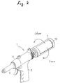
- Figures 1 and 2 show one example of prior blind rivet setting tools similar to that of above Japanese Patent Laid Open No.07-299539.
- a blind rivet setting tool 1 includes a handle 2, a hydraulic pressure generating means 3, and a housing 5.
- a nose 6 at the front end of the housing 5 is provided with a chuck mechanism (not shown) for holding the mandrel of the blind rivet.
- a path 9 is formed through which the broken piece of the mandrel passes from the nose of the front end to the rear end of the housing.
- the broken piece of the mandrel is transported into a collecting container 7, for example, by a suction negative mechanism or the like as shown in Figures 4(a) and (b) of Japanese Patent Laid Open No. 07-299539.
- a suction negative mechanism or the like as shown in Figures 4(a) and (b) of Japanese Patent Laid Open No. 07-299539.
- the collecting container 7 is rotated to align a opening 10 of the outer container portion with a opening of the inner container portion as shown in Figure 2, and then the broken pieces of the mandrels are discharged from that aligned openings for disposal.
- the lengths of the broken pieces of the mandrels are different according to their types. If the length of the broken piece is near the inner diameter of the collecting container, the broken pieces might be engaged with the inner wall of the container, so the broken pieces of the mandrels could not disposed. This situation is shown in Figures 3(a) and (b). If the broken pieces 11 of the mandrels are entangled to each other as shown in Figure 3(b), they block the outlet port of the path 9 to be accumulated within the path 9 of the housing, and finally they interfere with the operation of the blind rivet setting tool. Furthermore, in the case that the collecting container structure shown in Figure 2, there is a fear that the opening 10 could not be opened.
- Japanese Utility Model Laid Open No. 62-105735 discloses a safety cover assembly which prevents a risk of emitting the broken pieces, by mounting a cylindrical safety cover having a small diameter on the outlet port of the path for the broken pieces. Since this safety cover is for receiving the broken pieces one by one to discharge them outside, rather than for providing a collecting container for the broken pieces, it does not resolve the above problem of entangling of the broken pieces as discussed above.
- An object of the present invention is, in a fastener setting tool having a container for collecting the broken pieces of fasteners such as blind rivets or lock-bolts which are fastened by breaking its mandrel, to prevent or at least reduce the occurrence of the broken pieces of the mandrels from entangling with each other in the collecting container.
- a fastener setting tool which is constructed so that the mandrel of a fastener is inserted into a nose at the front end of the tool; the body of the fastener projected from the nose is inserted into the mounting hole of a workpiece such as panel; under that condition, the mandrel is pulled enough to break it to enlarge the shank of the fastener body to fix the fastener to a workpiece by the enlarged shank portion and a flange of the fastener body; and the fastener setting tool comprises a broken piece collection assembly for collecting, from the nose though a path within the tool, the broken pieces of the mandrels which are broken by the above pulling operation, characterized in that the broken piece collection assembly comprises a container enclosing the outlet port of the path and extending to elongate the path to collect the broken pieces discharged from the path, and a broken piece entangling prevention means disposed in the container, the broken piece entang
- the end face of the groove facing to the container bottom can be formed parallel to the container bottom to provide a stop face for the tip of the received broken piece.
- the groove bottom at the side of the container bottom can be inclined to become gradually shallower as the groove approaches the container bottom, providing a guide surface so that the tip of the received broken piece go out of the groove as it is advancing.
- the groove can include a cavity extending through a central portion of the broken piece receiver member, the cavity opens at least in two directions toward the side of the broken piece receiver member.
- the container bottom can be formed as a cap removable from the container body. Furthermore, the broken piece receiver member is preferably fixed to the cap. Also, the broken piece receiver member is preferably detachably fixed to the cap.
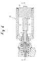
- FIGS 4 and 5 show a broken piece collecting assembly 13 according to a first embodiment of the present invention.
- the broken piece collecting assembly 13 includes a container 15 enclosing the outlet port 14 of the path 9 and extending to elongate the path 9 for collecting the broken pieces as discharged from the path 9.
- the container 15 is formed in a hollowed cylinder. It is fixed, at the outlet port 14 of the path for example by means of screws, to a holding portion 17 extending from the housing 5.
- the container extends to the rear side of the housing 5 to be in alignment with the axis of the path 9.
- the outer circumferential surface of the container 15 is provided with a rotary cover 18 having an opening 10 as previously described in Figure 2, which is capable to rotate to align with an opening (not shown) formed on an inner side wall 19. Through the alignment of both openings, the broken pieces contained within the container can be discharged outside.
- the broken piece collecting assembly 13 is provided with a broken piece entangling prevention means.
- the broken piece entangling prevention means comprises an elongated rod-like broken piece receiver member 22 extending along the axis 21 of the path 9 in the container 15.
- the broken piece receiver member 22 extends from a bottom cap 23 of the container located opposite side of the outlet port 14 toward the outlet port 14.
- the broken piece receiver member 22 is integrally molded into a shape upstanding from the central portion of a bottom cap 23. This allows the broken piece receiver member 22 to be mounted on the container 15 in alignment with the outlet port 14 of the path 9 by assembling the bottom cap 23 into the container15.
- the broken piece receiver member 22 is provided with an elongated groove 25 for receiving the broken piece of the mandrel of the fastener such as blind rivet in a posture that it is discharged from the outlet port 14 of the path 9.
- This groove 25 extends in a longitudinal direction at the center of the broken piece receiver member 22, and is formed to open at the side of the broken piece receiver member 22. This allows the broken piece discharged from the outlet port 14 of the path 9 to be temporarily received in the groove 25, and then to be discharged from the open portion 26 of the groove 25 into the container.
- the broken piece of the mandrel is transferred from the outlet port 14 to the groove 25 of the broken piece receiver member 22 by broken-piece-suction air pressure supplied to the path 9 through a pressurized air port 27 and an orifice 29.
- this suction air pressure refer to Japanese Patent Laid Open No.07-299539, in particular, Figure 4 and its relating description.
- a case of no suction air pressure applied is explained a bit.
- the broken piece When the broken pieces is discharged from the outlet port 14, the broken piece is received into the groove 25 in its posture along the axis 21 of the path 9 and advances in its posture as it is.
- the broken piece advancing within the groove 25 stops when its tip strikes against the stop face formed parallel to the container bottom of the groove 25.
- the broken piece After stopped, the broken piece is discharged into the container from the open portion 26 of the groove 25 in its posture along the axis 21by its own weight or the fastening operation.
- each of the broken pieces of the mandrels discharged from the path 9 is temporarily received by the broken piece receiver member 22 which keeps its posture in the axial direction, then it drops into the container, so that the broken piece would not upset within the container.
- the broken pieces are prevented from entangling each other. Furthermore, due to the broken piece receiver member 22, there is no enough space to upset the mandrel within the container. Thus, the broken pieces dropped into the container are also prevented from entangling each other. Therefore, the broken pieces within the container can smoothly be disposed, because of no obstacle to the fastening operation due to the entangling of the broken pieces.
- the material of the broken piece collecting assembly 13 may be either metal or plastic.
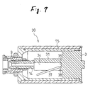
- Figures 6 and 7 show a broken piece collecting assembly 30 according to a second embodiment of the present invention.
- a broken piece collecting assembly 30 deals with a case that the broken piece of the mandrel is short in length.
- the broken piece receiver member 31 is formed to be larger in diameter and shorter in length than these of the broken piece receiver member 22 of the first embodiment.
- the bottom cap 33 is formed to be thicker so as to match the length of the broken piece receiver member 31. Because the broken piece receiver member 31has a large diameter, the groove 34 is formed to be deeper.
- the end face 35 of the groove 34 facing with the container bottom is formed parallel to the container bottom and provide a stop face for the tip of the received broken piece. Such a situation is shown in Figure 7.
- a broken piece 37 discharged from the outlet port 14 of the path 9 advances in the groove 37, then stops when its tip strikes against the stop face 35 of the groove 34, and drops on the side of the container 15 by it own weight. It is preferable to provide a projection on the stop face 35, which causes the broken piece to drop gently by engaging with the tip of the broken piece 37. Since other portions are same as those of the first embodiment, explanation therefor is omitted.
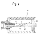
- Figures 8 and 9 show a broken piece collecting assembly 39 according to a third embodiment of the present invention.
- the shape of the groove of the broken piece receiver member of the first embodiment is modified.
- the groove 42 of the broken piece receiver member 41 is formed as a guide surface which is inclined so that the groove 42 becomes shallower as its bottom surface 43 approaches the bottom cap 45.
- the broken piece 37 transferred from the outlet port 14 of the path 9 is discharged from the groove 42 as its tip advances along the inclined guide surface of the groove bottom. Therefore, the broken piece is discharged from the groove while it is advancing in the groove. Since other portions are same as those of the first embodiment, explanation therefor is also omitted.
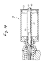
- Figures 10 and 11 show a broken piece collecting assembly 46 according to a fourth embodiment of the present invention.
- the shape of the groove of the broken piece receiver member of the first embodiment is modified, and also, the broken piece receiver member 47 and the bottom cap 49 are formed as discrete parts, and connected together by driving a outer threaded end portion 51 of the broken piece receiver member 47 into a inner threaded portion 50 formed at the center portion of the bottom cap 49.
- This structure enables the broken piece collecting assembly 46 to deal with the broken pieces having various lengths by exchanging the broken piece receiver member only.
- the groove of the broken piece receiver member 47 includes a cavity 53 which extends through the center portion of the broken piece receiver member.
- the cavity 53 further extends toward the side of the broken piece receiver member 47 and opens at three equidistantly (120°) spaced open portions 54.
- the number and spacing of the open portions 54 may be arbitrarily selected, for example, the number of the open portions 54 may be two, in addition to three as shown in Figure 11. In that case of two open portions, any spacing that the open portions are not diametrically aligned with each other may be selected. This is because if the two open portions are diametrically aligned, there is a fear that the broken pieces may be entangled each other across the broken piece receiver member.
- the broken piece can be received along the axis of the broken piece receiver member to keep the posture of the broken piece, thereby ensuring that broken piece is prevented from upsetting. Since other portions are same as those of the first embodiment, explanation therefor is also omitted.
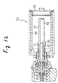
- Figure 12 shows a broken piece collecting assembly 55 according to a fifth embodiment of the present invention.
- the broken piece receiver member 57 of this broken piece collecting assembly 55 is not connected with the bottom cap 59 of the container 58, different from the broken piece receiver members of the first to fourth embodiments.
- the broken piece receiver member 57 is fixed to the outlet 14 of the path 9, the member 57 extends from the outlet port 14 and stops short of the bottom cap 59.
- the broken piece receiver member 57 is made of elastic materials so that it can be fitted in the outlet 14 of the path 9.
- the fitting portion 61 to the outlet 14 is snap fitted to the corresponding portion 62 of the outlet 14.
- the broken piece receiver member 57 is provided with a groove 63 for receiving the broken piece.
- the broken piece collection assembly of the present invention includes an elongated broken piece receiver member extending along the axis of the path in the container.
- the broken piece receiver member is provided with an elongated groove for receiving the broken piece discharged from the path in a posture as it is discharged.
- Each of the broken pieces of the mandrels is temporarily received by the broken piece receiver member which keeps its posture in the axial direction, and then drops it into the container, so that the broken piece would not upset in a diameter direction into engagement with the inner wall of the container. Consequently, entangling of the broken piece, resulting in blocking the outlet port of the path, can be effectively prevented even if many broken piece are contained within the container.
- the broken pieces within the container can smoothly be disposed because of no fastening obstacle due to the entangling of the broken pieces.
- the fasteners which can be used in the present invention may be of any type, such as blind rivets and lock-bolts so long as the mandrel of the fastener is broken during fastening operation.
- the broken piece collecting assembly can deal with the broken pieces having various lengths by only exchanging the broken piece receiver member.
Landscapes
- Engineering & Computer Science (AREA)
- Mechanical Engineering (AREA)
- Closures For Containers (AREA)
- Insertion Pins And Rivets (AREA)
- Containers And Packaging Bodies Having A Special Means To Remove Contents (AREA)
- Packaging Of Annular Or Rod-Shaped Articles, Wearing Apparel, Cassettes, Or The Like (AREA)
- Making Paper Articles (AREA)
- Hand Tools For Fitting Together And Separating, Or Other Hand Tools (AREA)
Abstract
Description
Claims (9)
- A fastener setting tool constructed so that the mandrel of a fastener is inserted into a nose at the front end of the tool; the body of the fastener projected from the nose is inserted into the mounting hole of a workpiece such as panel; under that condition, the mandrel is pulled enough to break it to enlarge the shank of the fastener body to fix the fastener to a workpiece by the enlarged shank portion and a flange of the fastener body; and the tool comprising a broken piece collection assembly for collecting, from the nose through a path within the tool, the broken pieces of the mandrels which are broken by the above pulling operation, characterized in that:the broken piece collection assembly comprises a container enclosing the outlet port of the path and extending to elongate the path to collect the broken pieces discharged from the path, and a broken piece entangling prevention means disposed in the container, the broken piece entangling prevention means comprising an elongated broken piece receiver member extending in the container along the axis of the path, the broken piece receiver member being provided with an elongated groove to receive the broken piece discharged from the path in the posture as it is discharged.
- A fastener setting tool of claim 1, wherein the container is formed in a hollowed cylinder, the broken piece receiver member comprises a rod member extending, to the outlet port of the path, from the container bottom located on the side opposite to the outlet port, the groove extends longitudinally along the broken piece receiver member and is formed to open on the side of the broken piece receiver member, so that the broken piece of the mandrel discharged from the outlet port of the path is temporarily received in the groove and then discharged into the container.
- A fastener setting tool of claim 2, wherein the end face of the groove facing with the container bottom is formed parallel to the container bottom to provide a stop face for the tip of the received broken piece.
- A fastener setting tool of claim 2, wherein the groove bottom at the side of the container bottom is inclined to become shallower as the groove approaches the container bottom to provide a guide surface so that the tip of the received broken piece goes out of the groove with its advance.
- A fastener setting tool of any one of claims 2 to 4, wherein the groove includes a cavity extending through a central portion of the broken piece receiver member, and the cavity opens at least in two directions toward the side of the broken piece receiver member.
- A fastener setting tool of any one of claims 2 to 5, wherein the container bottom is formed as a cap which is removable from the body of the container.
- A fastener setting tool of claim 6, wherein the broken receiver member is fixed to the cap.
- A fastener setting tool of claim 7, wherein the broken piece receiver member is detachably fixed to the cap.
- A fastener setting tool of any one of claims 2 to 6, wherein the broken piece receiver member is fixed to the outlet port of the path, and the receiver member extends from the outlet port of the path and stops short of the container bottom.
Applications Claiming Priority (2)
| Application Number | Priority Date | Filing Date | Title |
|---|---|---|---|
| JP11072322A JP2000263183A (en) | 1999-03-17 | 1999-03-17 | Broken piece recovering device for tightening tool |
| JP7232299 | 1999-03-17 |
Publications (3)
| Publication Number | Publication Date |
|---|---|
| EP1038608A2 true EP1038608A2 (en) | 2000-09-27 |
| EP1038608A3 EP1038608A3 (en) | 2000-12-13 |
| EP1038608B1 EP1038608B1 (en) | 2003-10-29 |
Family
ID=13485943
Family Applications (1)
| Application Number | Title | Priority Date | Filing Date |
|---|---|---|---|
| EP00301734A Expired - Lifetime EP1038608B1 (en) | 1999-03-17 | 2000-03-03 | Broken piece collecting assembly for fastener setting tool |
Country Status (6)
| Country | Link |
|---|---|
| US (1) | US6163945A (en) |
| EP (1) | EP1038608B1 (en) |
| JP (1) | JP2000263183A (en) |
| AT (1) | ATE252954T1 (en) |
| DE (1) | DE60006175T2 (en) |
| ES (1) | ES2208222T3 (en) |
Cited By (3)
| Publication number | Priority date | Publication date | Assignee | Title |
|---|---|---|---|---|
| GB2372475A (en) * | 2001-02-21 | 2002-08-28 | Textron Fastening Syst Ltd | Fastener installation tool including fastener-parts collection means |
| GB2442448A (en) * | 2006-10-03 | 2008-04-09 | Textron Fastening Syst Ltd | Improved Stem collection containers for fastening tools |
| CN104493056A (en) * | 2014-12-26 | 2015-04-08 | 苏州金逸康自动化设备有限公司 | Combined LED street lamp bracket riveting mold |
Families Citing this family (17)
| Publication number | Priority date | Publication date | Assignee | Title |
|---|---|---|---|---|
| USD462883S1 (en) | 2001-02-14 | 2002-09-17 | Emhart Llc | Rivet setting tool |
| EP1565289A4 (en) * | 2002-11-21 | 2006-05-03 | Newfrey Llc | Modular rivet tool |
| US7159291B2 (en) * | 2003-07-18 | 2007-01-09 | Opt Engineering Co., Ltd. | Continuous riveter and continuously caulking method of blind rivets |
| US20060180629A1 (en) * | 2005-02-17 | 2006-08-17 | Yu-Ching Lin | Close connection device of lid for a used-nail cylinder of a rivet gun |
| US20080060192A1 (en) * | 2006-07-13 | 2008-03-13 | Sps Technologies, Llc | High performance nosepiece for blind bolt installation |
| US7347078B1 (en) * | 2007-01-29 | 2008-03-25 | Sartam Industries, Inc. | Rivet holding container and rivet feed system for automatic feed blind rivet setting tool |
| IL181125A0 (en) * | 2007-02-01 | 2007-07-04 | Maktheshim Chemical Works Ltd | Polymorphs of 3-(e)-2-{2-[6-(2- |
| CN101712064B (en) * | 2008-10-08 | 2012-06-13 | 宝资工业股份有限公司 | Manual two-hand grip type nail pulling tool with collecting and discarding nail core device |
| DE102010039670A1 (en) * | 2010-08-24 | 2012-05-16 | Adolf Würth GmbH & Co. KG | rivet setting |
| DE102010039661A1 (en) * | 2010-08-24 | 2012-04-19 | Adolf Würth GmbH & Co. KG | rivet setting |
| US20120104304A1 (en) * | 2010-10-27 | 2012-05-03 | Yu-Ching Lin | Control valve for ejecting rivet pieces of a rivet gun |
| DE102013012075B4 (en) * | 2013-07-19 | 2025-11-20 | Richard Bergner Holding GmbH & Co. KG | Residual container for piece waste, especially for residual mandrels from blind rivets |
| CN207915402U (en) | 2018-02-13 | 2018-09-28 | 米沃奇电动工具公司 | Nose clip group for rivet setting tool |
| WO2021112281A1 (en) * | 2019-12-04 | 2021-06-10 | 김보경 | Lockbolt fastening system and lockbolt fastening device |
| JP7428379B2 (en) * | 2020-04-07 | 2024-02-06 | 株式会社ロブテックス | riveter |
| CN219632508U (en) | 2020-06-03 | 2023-09-05 | 米沃奇电动工具公司 | Rivet tools and power tools for setting rivets |
| WO2024010932A1 (en) | 2022-07-08 | 2024-01-11 | Milwaukee Electric Tool Corporation | Power tool sensing a multi-pole magnet junction |
Family Cites Families (13)
| Publication number | Priority date | Publication date | Assignee | Title |
|---|---|---|---|---|
| DE1303366B (en) * | 1964-07-22 | |||
| DE2154788A1 (en) * | 1971-11-04 | 1973-05-10 | Avdel Verbindungselemente | RIVETS FOR BLIND RIVETING |
| GB2025295B (en) * | 1978-06-24 | 1982-05-12 | Gesipa Blindniettechnik | Apparatus for collectingbroken-off mandrels of blind rivets |
| US4597263A (en) * | 1979-10-18 | 1986-07-01 | Huck Manufacturing Company | Pull type installation tool |
| DE3125838A1 (en) * | 1981-07-01 | 1983-01-27 | Manfred 6200 Wiesbaden Schwab | BLIND RIVET DEVICE WITH RIVET PIN PROCESSING |
| JPS62105735A (en) * | 1985-10-31 | 1987-05-16 | Nissan Motor Co Ltd | Step device for automobile |
| US4887450A (en) * | 1988-03-31 | 1989-12-19 | Textron, Inc. | Fastener stem collection apparatus and method |
| US4888974A (en) * | 1989-02-02 | 1989-12-26 | Emhart Industries, Inc. | Control valve for a mandrel collection system |
| US5086551A (en) * | 1990-09-05 | 1992-02-11 | Emhart Inc. | Rivet setting tool |
| JP3246092B2 (en) * | 1993-06-30 | 2002-01-15 | 松下電器産業株式会社 | Phone |
| US5598619A (en) * | 1994-05-09 | 1997-02-04 | Huck International, Inc. | Hydraulic installation tool |
| JPH07299539A (en) * | 1994-05-09 | 1995-11-14 | Pop Rivet Fastener Kk | Device for collecting rupture piece of fastening member in fastening tool |
| US5485727A (en) * | 1994-11-14 | 1996-01-23 | Gbp Corporation | Fastener installation tool |
-
1999
- 1999-03-17 JP JP11072322A patent/JP2000263183A/en active Pending
-
2000
- 2000-03-03 AT AT00301734T patent/ATE252954T1/en not_active IP Right Cessation
- 2000-03-03 DE DE60006175T patent/DE60006175T2/en not_active Expired - Fee Related
- 2000-03-03 ES ES00301734T patent/ES2208222T3/en not_active Expired - Lifetime
- 2000-03-03 EP EP00301734A patent/EP1038608B1/en not_active Expired - Lifetime
- 2000-03-10 US US09/522,665 patent/US6163945A/en not_active Expired - Fee Related
Cited By (9)
| Publication number | Priority date | Publication date | Assignee | Title |
|---|---|---|---|---|
| GB2372475A (en) * | 2001-02-21 | 2002-08-28 | Textron Fastening Syst Ltd | Fastener installation tool including fastener-parts collection means |
| GB2372475B (en) * | 2001-02-21 | 2003-12-17 | Textron Fastening Syst Ltd | Fastener installation tool including fastener-parts collection means |
| GB2394686A (en) * | 2001-02-21 | 2004-05-05 | Textron Fastening Syst Ltd | Fastener installation tool including fastener-parts collection means |
| GB2394686B (en) * | 2001-02-21 | 2004-10-06 | Textron Fastening Syst Ltd | Fastener installation tool including fastener-parts collection means |
| US6883216B2 (en) | 2001-02-21 | 2005-04-26 | Textron Fastening Systems Limited | Fastener installation tool including fastener-parts collection means |
| GB2442448A (en) * | 2006-10-03 | 2008-04-09 | Textron Fastening Syst Ltd | Improved Stem collection containers for fastening tools |
| GB2442448B (en) * | 2006-10-03 | 2009-02-18 | Textron Fastening Syst Ltd | Improved stem collection containers for fastening tools |
| CN104493056A (en) * | 2014-12-26 | 2015-04-08 | 苏州金逸康自动化设备有限公司 | Combined LED street lamp bracket riveting mold |
| CN104493056B (en) * | 2014-12-26 | 2016-05-11 | 苏州金逸康自动化设备有限公司 | A kind of LED street lamp bracket riveted group mould |
Also Published As
| Publication number | Publication date |
|---|---|
| EP1038608B1 (en) | 2003-10-29 |
| DE60006175T2 (en) | 2004-07-29 |
| DE60006175D1 (en) | 2003-12-04 |
| ATE252954T1 (en) | 2003-11-15 |
| ES2208222T3 (en) | 2004-06-16 |
| EP1038608A3 (en) | 2000-12-13 |
| JP2000263183A (en) | 2000-09-26 |
| US6163945A (en) | 2000-12-26 |
Similar Documents
| Publication | Publication Date | Title |
|---|---|---|
| US6163945A (en) | Broken piece collecting assembly for fastener setting tool | |
| US4519536A (en) | Apparatus for driving nails using an impact hammer | |
| CA2219259C (en) | Lockable telescoping screwdriver | |
| US4920833A (en) | Blind setting rivet | |
| EP0757935A1 (en) | Screw driver with replaceable nose for collated screws | |
| EP0349163A2 (en) | Nail driving device with improved nail feeding mechanism | |
| RU2435994C2 (en) | Blind rivet, method and device for installation of such rivet | |
| JPH0285510A (en) | Self-closing blind clamping tool | |
| JPS62502390A (en) | Offset tool and cartridge tip assembly | |
| CA2346950C (en) | Punch guide assembly | |
| CN113211652B (en) | Hole cutter with plug ejection and method thereof | |
| US4137747A (en) | Collector for broken-off fastener parts | |
| US6032510A (en) | Blind rivet setting tool | |
| US5996875A (en) | Power actuated fastening tool | |
| US20020002775A1 (en) | Tool chuck for a hand-held power-driven punching machine or the like | |
| EP1606069B1 (en) | Offset nose assembly with improved deflector and guard assemblies | |
| US6997269B1 (en) | Attachment for impact hammer | |
| US5519927A (en) | Rivet setting tool | |
| JP3793303B2 (en) | Fastener driving machine feeding device | |
| CA1198616A (en) | Combination hole-drilling and fastener-driving tools | |
| CN222588018U (en) | Anti-jamming pulling rivet gun and pulling claw outer sleeve of pulling rivet gun | |
| HU204458B (en) | Nail-driving device | |
| EP1671729A2 (en) | Locking mechanism for power drivable chuck | |
| JPH0243542Y2 (en) | ||
| CA2623342C (en) | Screwdriver with replaceable nose for collated screws |
Legal Events
| Date | Code | Title | Description |
|---|---|---|---|
| PUAI | Public reference made under article 153(3) epc to a published international application that has entered the european phase |
Free format text: ORIGINAL CODE: 0009012 |
|
| AK | Designated contracting states |
Kind code of ref document: A2 Designated state(s): AT BE CH CY DE DK ES FI FR GB GR IE IT LI LU MC NL PT SE |
|
| AX | Request for extension of the european patent |
Free format text: AL;LT;LV;MK;RO;SI |
|
| PUAL | Search report despatched |
Free format text: ORIGINAL CODE: 0009013 |
|
| AK | Designated contracting states |
Kind code of ref document: A3 Designated state(s): AT BE CH CY DE DK ES FI FR GB GR IE IT LI LU MC NL PT SE |
|
| AX | Request for extension of the european patent |
Free format text: AL;LT;LV;MK;RO;SI |
|
| RIC1 | Information provided on ipc code assigned before grant |
Free format text: 7B 21J 15/04 A, 7B 21J 15/06 B |
|
| AKX | Designation fees paid |
Free format text: AT BE CH CY DE DK ES FI FR GB GR IE IT LI LU MC NL PT SE |
|
| 17P | Request for examination filed |
Effective date: 20010810 |
|
| RAP1 | Party data changed (applicant data changed or rights of an application transferred) |
Owner name: EMHART LLC |
|
| 17Q | First examination report despatched |
Effective date: 20020827 |
|
| RAP1 | Party data changed (applicant data changed or rights of an application transferred) |
Owner name: NEWFREY LLC |
|
| GRAH | Despatch of communication of intention to grant a patent |
Free format text: ORIGINAL CODE: EPIDOS IGRA |
|
| GRAS | Grant fee paid |
Free format text: ORIGINAL CODE: EPIDOSNIGR3 |
|
| GRAA | (expected) grant |
Free format text: ORIGINAL CODE: 0009210 |
|
| AK | Designated contracting states |
Kind code of ref document: B1 Designated state(s): AT BE CH CY DE DK ES FI FR GB GR IE IT LI LU MC NL PT SE |
|
| PG25 | Lapsed in a contracting state [announced via postgrant information from national office to epo] |
Ref country code: NL Free format text: LAPSE BECAUSE OF FAILURE TO SUBMIT A TRANSLATION OF THE DESCRIPTION OR TO PAY THE FEE WITHIN THE PRESCRIBED TIME-LIMIT Effective date: 20031029 Ref country code: LI Free format text: LAPSE BECAUSE OF FAILURE TO SUBMIT A TRANSLATION OF THE DESCRIPTION OR TO PAY THE FEE WITHIN THE PRESCRIBED TIME-LIMIT Effective date: 20031029 Ref country code: IT Free format text: LAPSE BECAUSE OF FAILURE TO SUBMIT A TRANSLATION OF THE DESCRIPTION OR TO PAY THE FEE WITHIN THE PRESCRIBED TIME-LIMIT;WARNING: LAPSES OF ITALIAN PATENTS WITH EFFECTIVE DATE BEFORE 2007 MAY HAVE OCCURRED AT ANY TIME BEFORE 2007. THE CORRECT EFFECTIVE DATE MAY BE DIFFERENT FROM THE ONE RECORDED. Effective date: 20031029 Ref country code: FI Free format text: LAPSE BECAUSE OF FAILURE TO SUBMIT A TRANSLATION OF THE DESCRIPTION OR TO PAY THE FEE WITHIN THE PRESCRIBED TIME-LIMIT Effective date: 20031029 Ref country code: CY Free format text: LAPSE BECAUSE OF FAILURE TO SUBMIT A TRANSLATION OF THE DESCRIPTION OR TO PAY THE FEE WITHIN THE PRESCRIBED TIME-LIMIT Effective date: 20031029 Ref country code: CH Free format text: LAPSE BECAUSE OF FAILURE TO SUBMIT A TRANSLATION OF THE DESCRIPTION OR TO PAY THE FEE WITHIN THE PRESCRIBED TIME-LIMIT Effective date: 20031029 Ref country code: BE Free format text: LAPSE BECAUSE OF FAILURE TO SUBMIT A TRANSLATION OF THE DESCRIPTION OR TO PAY THE FEE WITHIN THE PRESCRIBED TIME-LIMIT Effective date: 20031029 Ref country code: AT Free format text: LAPSE BECAUSE OF FAILURE TO SUBMIT A TRANSLATION OF THE DESCRIPTION OR TO PAY THE FEE WITHIN THE PRESCRIBED TIME-LIMIT Effective date: 20031029 |
|
| REG | Reference to a national code |
Ref country code: GB Ref legal event code: FG4D |
|
| REG | Reference to a national code |
Ref country code: CH Ref legal event code: EP |
|
| REG | Reference to a national code |
Ref country code: IE Ref legal event code: FG4D |
|
| REF | Corresponds to: |
Ref document number: 60006175 Country of ref document: DE Date of ref document: 20031204 Kind code of ref document: P |
|
| RAP2 | Party data changed (patent owner data changed or rights of a patent transferred) |
Owner name: NEWFREY LLC |
|
| PG25 | Lapsed in a contracting state [announced via postgrant information from national office to epo] |
Ref country code: SE Free format text: LAPSE BECAUSE OF FAILURE TO SUBMIT A TRANSLATION OF THE DESCRIPTION OR TO PAY THE FEE WITHIN THE PRESCRIBED TIME-LIMIT Effective date: 20040129 Ref country code: GR Free format text: LAPSE BECAUSE OF FAILURE TO SUBMIT A TRANSLATION OF THE DESCRIPTION OR TO PAY THE FEE WITHIN THE PRESCRIBED TIME-LIMIT Effective date: 20040129 Ref country code: DK Free format text: LAPSE BECAUSE OF FAILURE TO SUBMIT A TRANSLATION OF THE DESCRIPTION OR TO PAY THE FEE WITHIN THE PRESCRIBED TIME-LIMIT Effective date: 20040129 |
|
| PG25 | Lapsed in a contracting state [announced via postgrant information from national office to epo] |
Ref country code: LU Free format text: LAPSE BECAUSE OF NON-PAYMENT OF DUE FEES Effective date: 20040303 Ref country code: IE Free format text: LAPSE BECAUSE OF NON-PAYMENT OF DUE FEES Effective date: 20040303 |
|
| PG25 | Lapsed in a contracting state [announced via postgrant information from national office to epo] |
Ref country code: MC Free format text: LAPSE BECAUSE OF NON-PAYMENT OF DUE FEES Effective date: 20040331 |
|
| NLT2 | Nl: modifications (of names), taken from the european patent patent bulletin |
Owner name: NEWFREY LLC |
|
| NLV1 | Nl: lapsed or annulled due to failure to fulfill the requirements of art. 29p and 29m of the patents act | ||
| REG | Reference to a national code |
Ref country code: CH Ref legal event code: PL |
|
| REG | Reference to a national code |
Ref country code: ES Ref legal event code: FG2A Ref document number: 2208222 Country of ref document: ES Kind code of ref document: T3 |
|
| ET | Fr: translation filed | ||
| PLBE | No opposition filed within time limit |
Free format text: ORIGINAL CODE: 0009261 |
|
| STAA | Information on the status of an ep patent application or granted ep patent |
Free format text: STATUS: NO OPPOSITION FILED WITHIN TIME LIMIT |
|
| 26N | No opposition filed |
Effective date: 20040730 |
|
| REG | Reference to a national code |
Ref country code: IE Ref legal event code: MM4A |
|
| PGFP | Annual fee paid to national office [announced via postgrant information from national office to epo] |
Ref country code: GB Payment date: 20050223 Year of fee payment: 6 |
|
| PGFP | Annual fee paid to national office [announced via postgrant information from national office to epo] |
Ref country code: FR Payment date: 20050321 Year of fee payment: 6 |
|
| PGFP | Annual fee paid to national office [announced via postgrant information from national office to epo] |
Ref country code: ES Payment date: 20050407 Year of fee payment: 6 |
|
| PGFP | Annual fee paid to national office [announced via postgrant information from national office to epo] |
Ref country code: DE Payment date: 20050502 Year of fee payment: 6 |
|
| PG25 | Lapsed in a contracting state [announced via postgrant information from national office to epo] |
Ref country code: GB Free format text: LAPSE BECAUSE OF NON-PAYMENT OF DUE FEES Effective date: 20060303 |
|
| PG25 | Lapsed in a contracting state [announced via postgrant information from national office to epo] |
Ref country code: ES Free format text: LAPSE BECAUSE OF NON-PAYMENT OF DUE FEES Effective date: 20060304 |
|
| PG25 | Lapsed in a contracting state [announced via postgrant information from national office to epo] |
Ref country code: DE Free format text: LAPSE BECAUSE OF NON-PAYMENT OF DUE FEES Effective date: 20061003 |
|
| GBPC | Gb: european patent ceased through non-payment of renewal fee |
Effective date: 20060303 |
|
| REG | Reference to a national code |
Ref country code: FR Ref legal event code: ST Effective date: 20061130 |
|
| REG | Reference to a national code |
Ref country code: ES Ref legal event code: FD2A Effective date: 20060304 |
|
| PG25 | Lapsed in a contracting state [announced via postgrant information from national office to epo] |
Ref country code: PT Free format text: LAPSE BECAUSE OF NON-PAYMENT OF DUE FEES Effective date: 20040329 |
|
| PG25 | Lapsed in a contracting state [announced via postgrant information from national office to epo] |
Ref country code: FR Free format text: LAPSE BECAUSE OF NON-PAYMENT OF DUE FEES Effective date: 20060331 |