EP1038595B1 - System for cleaning fiber optic connectors - Google Patents
System for cleaning fiber optic connectors Download PDFInfo
- Publication number
- EP1038595B1 EP1038595B1 EP00105637A EP00105637A EP1038595B1 EP 1038595 B1 EP1038595 B1 EP 1038595B1 EP 00105637 A EP00105637 A EP 00105637A EP 00105637 A EP00105637 A EP 00105637A EP 1038595 B1 EP1038595 B1 EP 1038595B1
- Authority
- EP
- European Patent Office
- Prior art keywords
- cleaner
- fiber optic
- circuit board
- cleaning
- optic connector
- Prior art date
- Legal status (The legal status is an assumption and is not a legal conclusion. Google has not performed a legal analysis and makes no representation as to the accuracy of the status listed.)
- Expired - Lifetime
Links
- 238000004140 cleaning Methods 0.000 title claims description 53
- 239000000835 fiber Substances 0.000 title claims description 46
- 230000013011 mating Effects 0.000 claims description 36
- 230000000295 complement effect Effects 0.000 claims description 4
- 238000003780 insertion Methods 0.000 claims description 3
- 230000037431 insertion Effects 0.000 claims description 3
- 210000001331 nose Anatomy 0.000 description 28
- 239000004744 fabric Substances 0.000 description 14
- 230000000712 assembly Effects 0.000 description 7
- 238000000429 assembly Methods 0.000 description 7
- 239000013307 optical fiber Substances 0.000 description 7
- 230000003287 optical effect Effects 0.000 description 6
- LFQSCWFLJHTTHZ-UHFFFAOYSA-N Ethanol Chemical compound CCO LFQSCWFLJHTTHZ-UHFFFAOYSA-N 0.000 description 4
- 239000000428 dust Substances 0.000 description 3
- 239000000463 material Substances 0.000 description 3
- 230000002745 absorbent Effects 0.000 description 2
- 239000002250 absorbent Substances 0.000 description 2
- 230000000694 effects Effects 0.000 description 2
- 239000002991 molded plastic Substances 0.000 description 2
- 229920001410 Microfiber Polymers 0.000 description 1
- 229920005830 Polyurethane Foam Polymers 0.000 description 1
- 238000003491 array Methods 0.000 description 1
- 230000005540 biological transmission Effects 0.000 description 1
- 239000000919 ceramic Substances 0.000 description 1
- 239000012459 cleaning agent Substances 0.000 description 1
- 230000003750 conditioning effect Effects 0.000 description 1
- 239000000356 contaminant Substances 0.000 description 1
- 238000011109 contamination Methods 0.000 description 1
- 239000002657 fibrous material Substances 0.000 description 1
- NBVXSUQYWXRMNV-UHFFFAOYSA-N fluoromethane Chemical compound FC NBVXSUQYWXRMNV-UHFFFAOYSA-N 0.000 description 1
- 239000011521 glass Substances 0.000 description 1
- 230000000977 initiatory effect Effects 0.000 description 1
- 239000000314 lubricant Substances 0.000 description 1
- 230000001050 lubricating effect Effects 0.000 description 1
- 239000002184 metal Substances 0.000 description 1
- 239000011496 polyurethane foam Substances 0.000 description 1
- 239000011347 resin Substances 0.000 description 1
- 229920005989 resin Polymers 0.000 description 1
- 229920006395 saturated elastomer Polymers 0.000 description 1
Images



Classifications
-
- G—PHYSICS
- G02—OPTICS
- G02B—OPTICAL ELEMENTS, SYSTEMS OR APPARATUS
- G02B6/00—Light guides; Structural details of arrangements comprising light guides and other optical elements, e.g. couplings
- G02B6/24—Coupling light guides
- G02B6/36—Mechanical coupling means
- G02B6/38—Mechanical coupling means having fibre to fibre mating means
- G02B6/3807—Dismountable connectors, i.e. comprising plugs
- G02B6/3833—Details of mounting fibres in ferrules; Assembly methods; Manufacture
- G02B6/3866—Devices, tools or methods for cleaning connectors
-
- B—PERFORMING OPERATIONS; TRANSPORTING
- B08—CLEANING
- B08B—CLEANING IN GENERAL; PREVENTION OF FOULING IN GENERAL
- B08B1/00—Cleaning by methods involving the use of tools
- B08B1/10—Cleaning by methods involving the use of tools characterised by the type of cleaning tool
- B08B1/14—Wipes; Absorbent members, e.g. swabs or sponges
- B08B1/143—Wipes
-
- B—PERFORMING OPERATIONS; TRANSPORTING
- B08—CLEANING
- B08B—CLEANING IN GENERAL; PREVENTION OF FOULING IN GENERAL
- B08B11/00—Cleaning flexible or delicate articles by methods or apparatus specially adapted thereto
-
- G—PHYSICS
- G02—OPTICS
- G02B—OPTICAL ELEMENTS, SYSTEMS OR APPARATUS
- G02B6/00—Light guides; Structural details of arrangements comprising light guides and other optical elements, e.g. couplings
- G02B6/24—Coupling light guides
- G02B6/36—Mechanical coupling means
- G02B6/38—Mechanical coupling means having fibre to fibre mating means
- G02B6/3807—Dismountable connectors, i.e. comprising plugs
-
- B—PERFORMING OPERATIONS; TRANSPORTING
- B08—CLEANING
- B08B—CLEANING IN GENERAL; PREVENTION OF FOULING IN GENERAL
- B08B2240/00—Type of materials or objects being cleaned
- B08B2240/02—Optical fibers or optical fiber connectors
-
- G—PHYSICS
- G02—OPTICS
- G02B—OPTICAL ELEMENTS, SYSTEMS OR APPARATUS
- G02B6/00—Light guides; Structural details of arrangements comprising light guides and other optical elements, e.g. couplings
- G02B6/24—Coupling light guides
- G02B6/36—Mechanical coupling means
- G02B6/38—Mechanical coupling means having fibre to fibre mating means
- G02B6/3807—Dismountable connectors, i.e. comprising plugs
- G02B6/3897—Connectors fixed to housings, casing, frames or circuit boards
Definitions
- This invention generally relates to the art of fiber optic connectors and, particularly, to a system for cleaning the end of a ferrule of a fiber optic connector mounted on a backplane of a chassis adapted for receiving a printed circuit board.
- a typical fiber optic connector includes a ferrule which mounts and positions an optical fiber or fibers within the connector.
- the ferrule may be fabricated of such material as ceramic or glass filled resin.
- a ferrule holder or other housing component of the connector embraces the ferrule and may be fabricated of such material as molded plastic.
- a spring may be disposed within the housing or ferrule holder such that the ferrule is yieldably biased forwardly for engaging another fiber-mounting ferrule of a mating connecting device.
- Such fiber optic connectors typically are connected end-to-end. In other words, two opposite end surfaces of opposing ferrules are mated to directly connect opposing end surfaces of the optical fibers to each other.
- the connectors should provide excellent connection characteristics. However, major problems are encountered if the ferrule end surfaces become contaminated by dust, oil or other contaminants which will cause the connection characteristics to become markedly deteriorated.
- cleaners have been provided to clean the ferrule end surfaces of fiber optic connectors.
- the cleaners typically include some form of soft cloth or paper which is moved over the ferrule end surfaces.
- the cloth or paper may be dampened with a cleaning solution such as ethanol.
- Fluorocarbon gas may also be used to remove excessive ethanol and any cloth or paper dust.
- the document US-A-5220703 describes an apparatus for cleaning the ferrule end surface of an optical connector.
- the optical connector cleaner comprises a cleaning cloth woven with ultrafine fiber less than 0.1 denier; a casing formed with at least one opening for protecting the cleaning cloth from dust; and a mechanism for shifting the cleaning cloth exposed in the opening for cloth renewing, after the ferrule end surface has been rubbed with the cleaning cloth for cleaning.
- the cloth shift mechanism is operated manually by the user or automatically by a motor.
- a holder jig holds the optical connector to facilitate cleaning of the ferrule end surface.
- the holder jig supports the optical connector such that the ferrule projects from the holder jig.
- cleaners of the character described above have proven effective for their intended purposes, they have limitations in that the fiber optic connectors typically are "brought to" the cleaner or there is easy access of the cleaner to the connectors. In other words, the connectors are easily moved to positions in engagement with the cleaner. Such cleaners are extremely difficult to use and, often, are not effective where there is limited access to the connectors, such as where the connectors are located in a remote or confined area. Still further, it is difficult, if not impossible, to use most existing cleaners on the ferrule end surfaces of connectors which are mounted in adapter assemblies. The connectors must be removed from the adapters in order to be cleaned. This problem equally exists when a ferrule end surface is located inwardly or recessed within a mating end face of a connector. The present invention is directed to solving this myriad of interrelated problems.
- the document US-A-4428092 discloses an apparatus for conditioning, in particular cleaning or lubricating pin arrays of an electrical interconnection backplane.
- a connector block with contacts removed is mounted on the end of a dummy circuit board.
- the connector block is slotted across the contact chambers, the slot having an absorbent element fitted therein.
- the element which may be of a polyurethane foam, is saturated with a cleaning or lubricating agent.
- the dummy board is fitted between the guide frames until the backplane pins pierce the absorbent element, the latter being "selfhealing" when the apparatus is withdrawn.
- An object, therefore, of the invention is to provide a new and improved system for cleaning fiber optic connectors, such as cleaning the end of a Iferrule of a fiber optic connector.
- Another object of the invention is to provide such a cleaning system wherein the fiber optic connector is mounted on a backplane of a chassis adapted for receiving a printed circuit board having a mating connector mateable with the fiber optic connector.
- the system includes a dummy circuit board receivable by the chassis.
- a cleaner is mounted on the dummy circuit board for cleaning the end of the ferrule of the fiber optic connector when the dummy circuit board is received by the chassis. Therefore, the actual printed circuit board can be removed from the chassis and the dummy circuit board, along with the cleaner, inserted into the chassis for cleaning purposes, whereafter the actual printed circuit board can be repositioned.
- the dummy circuit board includes a cut-out portion within which at least a portion of the cleaner is mounted.
- Complementary interengaging mounting means are provided between the cleaner and the dummy circuit board for mounting the cleaner on the board at different positions to accommodate the fiber optic connector being mounted at different locations on the backplane.
- the mounting means include a plurality of mounting holes in the dummy circuit board for receiving fastening means from the cleaner.
- the cleaner includes a mating portion for mating the cleaner with the fiber optic connector on the backplane.
- the mating portion is formed by a mating nose for insertion into a mating receptacle of the fiber optic connector.
- the nose includes an opening in a distal end thereof at which a cleaning medium of the cleaner is exposed.
- the cleaner includes a cleaning tape and an advancing mechanism for advancing the cleaning tape past the ferrule end of the fiber optic connector when the dummy circuit board is received by the chassis.
- a supply reel is provided for supplying the cleaning tape
- a take-up reel is provided for taking-up the cleaning tape from the supply reel.
- a ratcheting mechanism rotates one of the reels for incrementally advancing the cleaning tape.
- a pawl prevents rotation of at least the one reel.
- Gear means interconnect the supply reel and the take-up reel for conjoint rotation.
- a cleaner generally designated 14, is provided for cleaning the end of a ferrule of a fiber optic connector as will described hereinafter in relation to Figure 6.
- the cleaner includes a housing 16 and a cover 18 defining an interior cavity 20 therebetween.
- the cover has five holes 22 (Fig. 1) for receiving appropriate screws or other fasteners insertable into five internally threaded holes 24 (Fig. 2) to hold the cover on the housing and to gain access to interior cavity 20.
- the housing has four additional internally threaded mounting holes 26, for purposes described hereinafter.
- Cover 18 has two holes 27 aligned with two of the holes 26 in housing 16. Housing 16 and cover 18 may be fabricated of molded plastic, die-cast metal or other appropriate material.
- a unique feature of cleaner 14 is the provision of a mating portion for mating the cleaner with a fiber optic connector, as will be seen hereinafter.
- the mating portion herein is formed by an elongated mating nose 28 which has a through passage 28a (Figs. 5 and 6) and which communicates with interior cavity 20, as at 28b (Figs. 2 and 3).
- Mating nose 28 can be formed integrally with housing 16, or the mating nose can be a separate member (as shown) having a rear end slidably mounted within a channel 30 of housing 16.
- the nose is spring loaded by spring 31 located between a portion 33 of the nose and the housing 16.
- the nose 28 includes a projection 35 which extends from the rear end of the nose located in channel 30. The projection 35 engages a portion of housing 16 to retain the rear end of the nose within the channel 30.
- Mating nose 28 has an opening 28c in the distal end of the nose.
- a backing block 32 is pivotally mounted by pivot trunions 32a press-fit within notches 34 in the end of the nose. Therefore, the backing block can pivot to accommodate varying angles of the ends of the ferrules of fiber optic connectors, as will be understood hereinafter.
- a supply reel 36 and a take-up reel 38 are mounted within interior cavity 20 of housing 16 by a pair of bolts 40 and 42, respectively, which are threaded into the base of housing 16, as at 44 in Figure 4.
- the bolts are shanked, as at 46 (Fig. 4), to form shaft portions 40a and 42a about which the reels are free to rotate.
- supply reel 36 is fixed by a lock washer 48 to a gear 50
- take-up reel 38 is fixed by a pair of pins 52 to a second gear 54.
- the gears are in mesh, as at 56. Therefore, the supply reel and the take-up reel are coupled by the gears for conjoint rotation and for free rotation about shaft portions 40a and 42a of bolts 40 and 42, respectively.
- an advancing mechanism is provided for advancing a cleaning medium, such as a cleaning tape, from supply reel 36 over backing block 32 in nose 28 and back onto take-up reel 38.
- the advancing mechanism is a ratchet mechanism, generally designated 58 (Figs. 2-4).
- the ratchet mechanism includes a ratcheting handle 60 having an interior end 60a (Fig. 4) journalled for free rotation about a circular boss portion 50a of gear 50. Inner end 60a of ratcheting handle 60 is sandwiched between gear 50 and a toothed ratchet wheel 62.
- a pin 63 interlocks the gear and the ratchet wheel for conjoint rotation.
- a moving pawl 64 is fixed to the underside of ratcheting handle 64 by a fastener 66.
- a stop pawl 68 is fixed to housing 16 in the bottom of the cavity of the housing by a fastener 70. As seen in Figure 5, moving pawl 64 and stop pawl 68 are angled to engage teeth 62a about the periphery of ratched wheel 62 to effect movement of the ratchet wheel in the direction of arrow "A" (Fig. 5).
- ratcheting handle 60 when ratcheting handle 60 is moved from the full-line position to the phantom position shown in Figure 5, moving pawl 64 will incrementally rotate ratchet wheel 62 in the direction of arrow "A" and stop pawl 68 will prevent reverse rotation of the ratchet wheel.
- ratcheting handle 60 will effect incremental rotation of both supply reel 36 and take-up reel 38.
- the handle will be returned to its original position by a spring 51.
- ratcheting handle 60 will incrementally rotate ratchet wheel 62 through moving pawl 64. With the ratchet wheel fixed to gear 50 by pin 63 and with gear 50 being fixed to supply reel 36 by lock washer 48, incremental movement of ratcheting handle 60 incrementally rotates the supply reel.
- a cleaning tape 70 is shown being fed off of supply reel 36 around a guide roller 72 and into through passage 28b of mating nose 28.
- the cleaning tape is moved in a path around the front face of backing block 38 so that the cleaning tape is exposed at opening 28c of the mating nose.
- the cleaning tape then moves back through passage 28b into interior chamber 20 in the direction of arrow "E", around a second guide roller 74 and onto take-up reel 38. Therefore, a section of the cleaning tape will move past opening 28c of mating nose 28, around backing block 32, in response to each ratcheting action of handle 60.
- the cleaning tape can be fabricated of woven cloth, paper or other fabric or fibrous material appropriate for cleaning the end of a ferrule of a fiber optic connector.
- FIG. 6 shows how mating nose 28 of cleaner 14 can be mated in a receptacle 72 of an appropriate fiber optic connector assembly, generally designated 74.
- the assembly includes a fiber optic connector, generally designated 76, inserted into an adapter, generally designated 78.
- Connector 76 mounts a ferrule 80 which terminates one or more optical fibers 82.
- the ferrule has an end face 80a which can be readily cleaned by cleaner 14 of the invention.
- Mating nose 28 of the cleaner is inserted past a shutter 84 of adapter 78 so that opening 28c and backing block 32 at the distal end of mating nose 28 are juxtaposed in registry with end face 80a of ferrule 80.
- connector assembly 74 is but one example of the applicability or utility of cleaner 14. It specifically can be seen that mating nose 28 of the cleaner can access ferrules which are recessed within a fiber optic connector assembly. It also can be understood that by providing mating nose 28 as a separate component from housing 16, the nose can be interchanged with other mating noses of different configurations for different connector assemblies.
- Figure 6 also shows the significance of pivotally mounting backing block 32. In many fiber optic connectors, the end face 80a of ferrule 80 is maintained at an angle to the axis of optical fiber(s) 82 for mating with a similarly angled ferrule of a complementary mating connector. Pivotally mounted backing block 32 can accommodate varying angles of the ends of the ferrule.
- Figures 7-13 show a system for cleaning the end of a ferrule of a fiber optic connector mounted on a backplane 86 of a card frame or backplane chassis, generally designated 88, adapted for receiving a plurality of printed circuit boards 90.
- Card frame or backplane chassis 88 includes a plurality of guide rails 92 for receiving the top and bottom edges of printed circuit boards 90.
- a plurality of edge-card connectors 94 are mounted on backplane 86 in alignment with guide rails 92.
- Header connectors 96 are mounted at the leading edges of printed circuit boards 90 for connection within edge card connectors 94.
- the edge card connectors could be configured to directly engage circuit traces along the leading edges of the printed circuit boards.
- a plurality of fiber optic connector assemblies 74 (Fig.
- Printed circuit boards 90 have connectors mounted thereon for mating with fiber optic connector assemblies 74. The printed circuit boards are inserted into chassis 88 in the direction of arrow "F".
- backplane 86 is a "motherboard” and printed circuit boards 90 are "daughter boards" in the card frame or chassis of Figure 7.
- the cleaning system of the invention is equally applicable wherein printed circuit boards are used with connectors simply mounted on panels or frame components other than a motherboard. Therefore, the use of the term "backplane” herein and in the claims hereof is not limited to the backplane being a printed circuit board.
- FIG. 8-10 wherein it can be seen that cleaner 14 (Figs. 1-6) is mounted on an dummy circuit board 98 having a cut-out portion or opening 100.
- housing 16 of cleaner 14 has a section 102 of reduced dimensions sized for sliding in cut-out 100 in dummy circuit board 98.
- a frame piece 104 is mounted to the front of dummy circuit board 98, and the frame piece has an elongated opening 106 through which ratcheting handle 60 of the cleaner projects.
- Figure 8 shows one of the fiber optic connector assemblies 74 (Fig. 6) mounted on backplane 86 (Fig. 7) of the card frame or chassis 88.
- Dummy circuit board 98 has a second cut-out 108 for accommodating connector assembly 74.
- Mating nose 28 of cleaner 14 projects into cut-out 108 for insertion into connector assembly 74 to clean the ferrule thereof as described above in relation to Figure 6.
- Two rows 110 of mounting holes 112 are formed in dummy circuit board 98 to mount cleaner 14 on the dummy board at different positions to accommodate fiber optic connector assemblies 74 being mounted at different locations on backplane 86.
- Mounting holes 112 are located for alignment with mounting holes 26 (Fig. 2) in housing 16 of cleaner 14. Therefore, Figure 8 shows one position for mounting the cleaner on the dummy board to accommodate the location of connector assembly 74 in Figure 8.
- Figure 11 shows cleaner 14 moved upwardly relative to the position of Figure 8 by using differently positioned mounting holes 112.
- Figure 12 shows cleaner 14 moved downwardly from the position of Figure 8 for accommodating still a differently located fiber optic connector assembly 74.
- Figure 13 shows still another position of cleaner 14 on the dummy board at the extreme top range of mounting holes 112 to accommodate a fiber optic connector assembly at still a different location on the backplane.
- Readily removable fasteners can be used to position in the aligned holes and easily adjust the position of the cleaner on the backplane.
- an actual printed circuit board 90 can be removed from backplane chassis or card frame 88 (Fig. 7) to expose fiber optic connectors 74 on backplane 86.
- An operator simply recognizes the location of the fiber optic connector assembly which is to be cleaned and positions cleaner 14 on dummy circuit board 98 accordingly.
- the dummy circuit board and the cleaner then are inserted into the position where the actual printed circuit board has been removed, and mating nose 28 of the cleaner will be inserted into the receptacle of the fiber optic connector assembly on the backplane.
- cleaning tape 70 will be moved over the ferrule end face of the fiber optic connector assembly to clean the ferrule as described above.
- the dummy circuit board and the cleaner are pulled out of card frame 88, and the actual printed circuit board can be reinserted and mated with the cleaned connector assembly.
Landscapes
- Physics & Mathematics (AREA)
- General Physics & Mathematics (AREA)
- Optics & Photonics (AREA)
- Mechanical Coupling Of Light Guides (AREA)
Description
- This invention generally relates to the art of fiber optic connectors and, particularly, to a system for cleaning the end of a ferrule of a fiber optic connector mounted on a backplane of a chassis adapted for receiving a printed circuit board.
- Fiber optic connectors of a wide variety of designs have been employed to terminate optical fiber cables and to facilitate connection of the cables to other cables or other optical fiber transmission devices. A typical fiber optic connector includes a ferrule which mounts and positions an optical fiber or fibers within the connector. The ferrule may be fabricated of such material as ceramic or glass filled resin. A ferrule holder or other housing component of the connector embraces the ferrule and may be fabricated of such material as molded plastic. A spring may be disposed within the housing or ferrule holder such that the ferrule is yieldably biased forwardly for engaging another fiber-mounting ferrule of a mating connecting device.
- Such fiber optic connectors typically are connected end-to-end. In other words, two opposite end surfaces of opposing ferrules are mated to directly connect opposing end surfaces of the optical fibers to each other. The connectors should provide excellent connection characteristics. However, major problems are encountered if the ferrule end surfaces become contaminated by dust, oil or other contaminants which will cause the connection characteristics to become markedly deteriorated.
- In order to solve the contamination problems, cleaners have been provided to clean the ferrule end surfaces of fiber optic connectors. The cleaners typically include some form of soft cloth or paper which is moved over the ferrule end surfaces. The cloth or paper may be dampened with a cleaning solution such as ethanol. Fluorocarbon gas may also be used to remove excessive ethanol and any cloth or paper dust.
- The document
US-A-5220703 describes an apparatus for cleaning the ferrule end surface of an optical connector. In detail, it is described the combination of an optical connector cleaner and a holder jig. To microscopically clean the ferrule end surface of an optical connector simply, uniformly and securely, the optical connector cleaner comprises a cleaning cloth woven with ultrafine fiber less than 0.1 denier; a casing formed with at least one opening for protecting the cleaning cloth from dust; and a mechanism for shifting the cleaning cloth exposed in the opening for cloth renewing, after the ferrule end surface has been rubbed with the cleaning cloth for cleaning. Further, it is preferable to provide an elastic member under the cleaning cloth for applying a constant cleaning pressure against the cloth and a guide member over the cleaning cloth for securely cleaning the ferrule end surface. The cloth shift mechanism is operated manually by the user or automatically by a motor. A holder jig holds the optical connector to facilitate cleaning of the ferrule end surface. The holder jig supports the optical connector such that the ferrule projects from the holder jig. - While cleaners of the character described above have proven effective for their intended purposes, they have limitations in that the fiber optic connectors typically are "brought to" the cleaner or there is easy access of the cleaner to the connectors. In other words, the connectors are easily moved to positions in engagement with the cleaner. Such cleaners are extremely difficult to use and, often, are not effective where there is limited access to the connectors, such as where the connectors are located in a remote or confined area. Still further, it is difficult, if not impossible, to use most existing cleaners on the ferrule end surfaces of connectors which are mounted in adapter assemblies. The connectors must be removed from the adapters in order to be cleaned. This problem equally exists when a ferrule end surface is located inwardly or recessed within a mating end face of a connector. The present invention is directed to solving this myriad of interrelated problems.
- The document
US-A-4428092 discloses an apparatus for conditioning, in particular cleaning or lubricating pin arrays of an electrical interconnection backplane. A connector block with contacts removed is mounted on the end of a dummy circuit board. The connector block is slotted across the contact chambers, the slot having an absorbent element fitted therein. The element, which may be of a polyurethane foam, is saturated with a cleaning or lubricating agent. To clean or lubricate the pins, the dummy board is fitted between the guide frames until the backplane pins pierce the absorbent element, the latter being "selfhealing" when the apparatus is withdrawn. - An object, therefore, of the invention, is to provide a new and improved system for cleaning fiber optic connectors, such as cleaning the end of a Iferrule of a fiber optic connector.
- Another object of the invention is to provide such a cleaning system wherein the fiber optic connector is mounted on a backplane of a chassis adapted for receiving a printed circuit board having a mating connector mateable with the fiber optic connector.
- In the exemplary embodiment of the invention, the system includes a dummy circuit board receivable by the chassis. A cleaner is mounted on the dummy circuit board for cleaning the end of the ferrule of the fiber optic connector when the dummy circuit board is received by the chassis. Therefore, the actual printed circuit board can be removed from the chassis and the dummy circuit board, along with the cleaner, inserted into the chassis for cleaning purposes, whereafter the actual printed circuit board can be repositioned.
- As disclosed herein, the dummy circuit board includes a cut-out portion within which at least a portion of the cleaner is mounted. Complementary interengaging mounting means are provided between the cleaner and the dummy circuit board for mounting the cleaner on the board at different positions to accommodate the fiber optic connector being mounted at different locations on the backplane. The mounting means include a plurality of mounting holes in the dummy circuit board for receiving fastening means from the cleaner.
- The cleaner includes a mating portion for mating the cleaner with the fiber optic connector on the backplane. As disclosed herein, the mating portion is formed by a mating nose for insertion into a mating receptacle of the fiber optic connector. The nose includes an opening in a distal end thereof at which a cleaning medium of the cleaner is exposed.
- Specifically, the cleaner includes a cleaning tape and an advancing mechanism for advancing the cleaning tape past the ferrule end of the fiber optic connector when the dummy circuit board is received by the chassis. A supply reel is provided for supplying the cleaning tape, and a take-up reel is provided for taking-up the cleaning tape from the supply reel. A ratcheting mechanism rotates one of the reels for incrementally advancing the cleaning tape. A pawl prevents rotation of at least the one reel. Gear means interconnect the supply reel and the take-up reel for conjoint rotation.
- Other objects, features and advantages of the invention will be apparent from the following detailed description taken in connection with the accompanying drawings.
- The features of this invention which are believed to be novel are set forth with particularity in the appended claims. The invention, together with its objects and the advantages thereof, may be best understood by reference to the following description taken in conjunction with the accompanying drawings, in which like reference numerals identify like elements in the figures and in which:
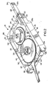
- FIGURE 1 is a perspective view of a cleaner for a fiber optic connector, according to the invention;
- FIGURE 2 is a perspective view similar to that of Figure 1, with the cover of the cleaner removed and without a cleaning tape in the cleaner;
- FIGURE 3 is a perspective view looking at the opposite end of the cleaner from that shown in Figure 2;
- FIGURE 4 is a vertical section taken generally along line 4-4 of Figure 1;
- FIGURE 5 is a top plan view of the cleaner, with the cleaning tape shown in phantom;
- FIGURE 6 is a fragmented section through the mating nose of the cleaner inserted into a fiber optic connector assembly;
- FIGURE 7 is a fragmented perspective view of a backplane chassis system within which the cleaner has considerable utility;
- FIGURE 8 is a side elevational view of the cleaner mounted on a dummy circuit board, with the mating nose of the cleaner inserted into a connector assembly on the backplane of the chassis of Figure 7;
- FIGURE 9 is a top plan view of the cleaner and dummy circuit board shown in Figure 8;
- FIGURE 10 is a front elevational view of the cleaner and dummy circuit board of Figure 8; and
- FIGURES 11-13 are views similar to that of Figure 8, showing the cleaner mounted at different positions on the dummy circuit board for cleaning various fiber optic connector assemblies mounted at different locations on the backplane.
- Referring to the drawings in greater detail, and first to Figures 1-4, a cleaner, generally designated 14, is provided for cleaning the end of a ferrule of a fiber optic connector as will described hereinafter in relation to Figure 6. The cleaner includes a
housing 16 and acover 18 defining aninterior cavity 20 therebetween. The cover has five holes 22 (Fig. 1) for receiving appropriate screws or other fasteners insertable into five internally threaded holes 24 (Fig. 2) to hold the cover on the housing and to gain access tointerior cavity 20. The housing has four additional internally threaded mountingholes 26, for purposes described hereinafter.Cover 18 has twoholes 27 aligned with two of theholes 26 inhousing 16.Housing 16 and cover 18 may be fabricated of molded plastic, die-cast metal or other appropriate material. - A unique feature of cleaner 14 is the provision of a mating portion for mating the cleaner with a fiber optic connector, as will be seen hereinafter. The mating portion herein is formed by an
elongated mating nose 28 which has a through passage 28a (Figs. 5 and 6) and which communicates withinterior cavity 20, as at 28b (Figs. 2 and 3).Mating nose 28 can be formed integrally withhousing 16, or the mating nose can be a separate member (as shown) having a rear end slidably mounted within achannel 30 ofhousing 16. The nose is spring loaded by spring 31 located between aportion 33 of the nose and thehousing 16. Thenose 28 includes aprojection 35 which extends from the rear end of the nose located inchannel 30. Theprojection 35 engages a portion ofhousing 16 to retain the rear end of the nose within thechannel 30. -
Mating nose 28 has anopening 28c in the distal end of the nose. Abacking block 32 is pivotally mounted bypivot trunions 32a press-fit withinnotches 34 in the end of the nose. Therefore, the backing block can pivot to accommodate varying angles of the ends of the ferrules of fiber optic connectors, as will be understood hereinafter. - A
supply reel 36 and a take-up reel 38 are mounted withininterior cavity 20 ofhousing 16 by a pair ofbolts housing 16, as at 44 in Figure 4. The bolts are shanked, as at 46 (Fig. 4), to formshaft portions 40a and 42a about which the reels are free to rotate. Actually, as best seen in Figure 4,supply reel 36 is fixed by a lock washer 48 to agear 50, and take-up reel 38 is fixed by a pair ofpins 52 to asecond gear 54. The gears are in mesh, as at 56. Therefore, the supply reel and the take-up reel are coupled by the gears for conjoint rotation and for free rotation aboutshaft portions 40a and 42a ofbolts - Generally, an advancing mechanism is provided for advancing a cleaning medium, such as a cleaning tape, from
supply reel 36 overbacking block 32 innose 28 and back onto take-up reel 38. Specifically, the advancing mechanism is a ratchet mechanism, generally designated 58 (Figs. 2-4). The ratchet mechanism includes a ratchetinghandle 60 having aninterior end 60a (Fig. 4) journalled for free rotation about a circular boss portion 50a ofgear 50.Inner end 60a of ratchetinghandle 60 is sandwiched betweengear 50 and atoothed ratchet wheel 62. A pin 63 interlocks the gear and the ratchet wheel for conjoint rotation. A movingpawl 64 is fixed to the underside of ratchetinghandle 64 by afastener 66. Astop pawl 68 is fixed tohousing 16 in the bottom of the cavity of the housing by afastener 70. As seen in Figure 5, movingpawl 64 and stoppawl 68 are angled to engageteeth 62a about the periphery ofratched wheel 62 to effect movement of the ratchet wheel in the direction of arrow "A" (Fig. 5). Specifically, when ratchetinghandle 60 is moved from the full-line position to the phantom position shown in Figure 5, movingpawl 64 will incrementally rotateratchet wheel 62 in the direction of arrow "A" and stoppawl 68 will prevent reverse rotation of the ratchet wheel. - From the foregoing, it can be understood that incremental movement of ratcheting
handle 60 will effect incremental rotation of bothsupply reel 36 and take-up reel 38. Once the force initiating the movement of the handle is removed, the handle will be returned to its original position by aspring 51. Specifically, ratchetinghandle 60 will incrementally rotateratchet wheel 62 through movingpawl 64. With the ratchet wheel fixed to gear 50 by pin 63 and withgear 50 being fixed to supplyreel 36 by lock washer 48, incremental movement of ratchetinghandle 60 incrementally rotates the supply reel. Continuing further, withgear 50 in mesh withgear 54 at 56, and withgear 54 fixed to take-up reel 38 bypins 52, incremental movement of ratchetingwheel 60 is effective to incrementally rotate take-up reel 38 in the direction of arrow "C" (Fig. 5). - With the above understanding of the advancing or ratcheting
mechanism 58 of cleaner 14, reference is made to Figure 5 wherein a cleaningtape 70 is shown being fed off ofsupply reel 36 around aguide roller 72 and into throughpassage 28b ofmating nose 28. The cleaning tape is moved in a path around the front face ofbacking block 38 so that the cleaning tape is exposed at opening 28c of the mating nose. The cleaning tape then moves back throughpassage 28b intointerior chamber 20 in the direction of arrow "E", around asecond guide roller 74 and onto take-up reel 38. Therefore, a section of the cleaning tape will move past opening 28c ofmating nose 28, around backingblock 32, in response to each ratcheting action ofhandle 60. The cleaning tape can be fabricated of woven cloth, paper or other fabric or fibrous material appropriate for cleaning the end of a ferrule of a fiber optic connector. - Figure 6 shows how
mating nose 28 of cleaner 14 can be mated in areceptacle 72 of an appropriate fiber optic connector assembly, generally designated 74. Actually, the assembly includes a fiber optic connector, generally designated 76, inserted into an adapter, generally designated 78.Connector 76 mounts aferrule 80 which terminates one or moreoptical fibers 82. The ferrule has anend face 80a which can be readily cleaned by cleaner 14 of the invention.Mating nose 28 of the cleaner is inserted past ashutter 84 ofadapter 78 so that opening 28c andbacking block 32 at the distal end ofmating nose 28 are juxtaposed in registry withend face 80a offerrule 80. - It should be understood that
connector assembly 74 is but one example of the applicability or utility of cleaner 14. It specifically can be seen thatmating nose 28 of the cleaner can access ferrules which are recessed within a fiber optic connector assembly. It also can be understood that by providingmating nose 28 as a separate component fromhousing 16, the nose can be interchanged with other mating noses of different configurations for different connector assemblies. Figure 6 also shows the significance of pivotally mountingbacking block 32. In many fiber optic connectors, theend face 80a offerrule 80 is maintained at an angle to the axis of optical fiber(s) 82 for mating with a similarly angled ferrule of a complementary mating connector. Pivotally mounted backingblock 32 can accommodate varying angles of the ends of the ferrule. - Figures 7-13 show a system for cleaning the end of a ferrule of a fiber optic connector mounted on a
backplane 86 of a card frame or backplane chassis, generally designated 88, adapted for receiving a plurality of printedcircuit boards 90. Card frame orbackplane chassis 88 includes a plurality ofguide rails 92 for receiving the top and bottom edges of printedcircuit boards 90. A plurality of edge-card connectors 94 are mounted onbackplane 86 in alignment with guide rails 92.Header connectors 96 are mounted at the leading edges of printedcircuit boards 90 for connection withinedge card connectors 94. Alternatively, the edge card connectors could be configured to directly engage circuit traces along the leading edges of the printed circuit boards. A plurality of fiber optic connector assemblies 74 (Fig. 6) are mounted at different locations onbackplane 86 generally in alignment withguide rails 92 and edge card connectors 94 (i.e., in alignment with the leading edges of printed circuit boards 90). Printedcircuit boards 90 have connectors mounted thereon for mating with fiberoptic connector assemblies 74. The printed circuit boards are inserted intochassis 88 in the direction of arrow "F". - It should be understood that the card frame or backplane chassis described above in relation to Figure 7 is but one application within which the cleaning system of the invention is applicable. In other words,
backplane 86 is a "motherboard" and printedcircuit boards 90 are "daughter boards" in the card frame or chassis of Figure 7. However, the cleaning system of the invention is equally applicable wherein printed circuit boards are used with connectors simply mounted on panels or frame components other than a motherboard. Therefore, the use of the term "backplane" herein and in the claims hereof is not limited to the backplane being a printed circuit board. - With that understanding, reference is made to Figures 8-10 wherein it can be seen that cleaner 14 (Figs. 1-6) is mounted on an
dummy circuit board 98 having a cut-out portion oropening 100. Referring back to Figure 1,housing 16 of cleaner 14 has asection 102 of reduced dimensions sized for sliding in cut-out 100 indummy circuit board 98. Aframe piece 104 is mounted to the front ofdummy circuit board 98, and the frame piece has anelongated opening 106 through which ratcheting handle 60 of the cleaner projects. Figure 8 shows one of the fiber optic connector assemblies 74 (Fig. 6) mounted on backplane 86 (Fig. 7) of the card frame orchassis 88.Dummy circuit board 98 has a second cut-out 108 for accommodatingconnector assembly 74.Mating nose 28 of cleaner 14 projects into cut-out 108 for insertion intoconnector assembly 74 to clean the ferrule thereof as described above in relation to Figure 6. - Two
rows 110 of mountingholes 112 are formed indummy circuit board 98 to mount cleaner 14 on the dummy board at different positions to accommodate fiberoptic connector assemblies 74 being mounted at different locations onbackplane 86. Mountingholes 112 are located for alignment with mounting holes 26 (Fig. 2) inhousing 16 of cleaner 14. Therefore, Figure 8 shows one position for mounting the cleaner on the dummy board to accommodate the location ofconnector assembly 74 in Figure 8. Figure 11 shows cleaner 14 moved upwardly relative to the position of Figure 8 by using differently positioned mountingholes 112. Figure 12 shows cleaner 14 moved downwardly from the position of Figure 8 for accommodating still a differently located fiberoptic connector assembly 74. Figure 13 shows still another position of cleaner 14 on the dummy board at the extreme top range of mountingholes 112 to accommodate a fiber optic connector assembly at still a different location on the backplane. Readily removable fasteners can be used to position in the aligned holes and easily adjust the position of the cleaner on the backplane. - With the system of Figures 7-13, it can be understood that an actual printed
circuit board 90 can be removed from backplane chassis or card frame 88 (Fig. 7) to exposefiber optic connectors 74 onbackplane 86. An operator simply recognizes the location of the fiber optic connector assembly which is to be cleaned and positions cleaner 14 ondummy circuit board 98 accordingly. The dummy circuit board and the cleaner then are inserted into the position where the actual printed circuit board has been removed, andmating nose 28 of the cleaner will be inserted into the receptacle of the fiber optic connector assembly on the backplane. By ratchetinghandle 60, cleaningtape 70 will be moved over the ferrule end face of the fiber optic connector assembly to clean the ferrule as described above. After cleaning, the dummy circuit board and the cleaner are pulled out ofcard frame 88, and the actual printed circuit board can be reinserted and mated with the cleaned connector assembly. - It will be understood that the invention may be embodied in other specific forms without departing from the spirit or central characteristics thereof. The present examples and embodiments, therefore, are to be considered in all respects as illustrative and not restrictive, and the invention is not to be limited to the details given herein.
Claims (11)
- A system for cleaning the end (80a) of a ferrule (80) of a fiber optic connector (74) mounted on a backplane (86) of a chassis (88) adapted for receiving a printed circuit board (90) having a mating connector mateable with the fiber optic connector, comprising:a dummy circuit board (98) receivable by said chassis (88); anda cleaner (14) mounted on the dummy circuit board (98) for cleaning the end (80a) of the ferrule of the fiber optic connector (74) when the dummy circuit board (98) is received by the chassis (88) characterised bythat said cleaner (14) includes a mating portion (28) for mating the cleaner with the fiber optic connector (74).
- The system of claim 1 wherein said dummy circuit board (98) includes a cut-out portion (100) within which at least a portion (102) of the cleaner (14) is mounted.
- The system of claim 1 or 2, including complementary mounting means (26,112) between the cleaner (14) and the dummy circuit board (98) for mounting the cleaner on the board at different positions to accommodate the fiber optic connector (74) being mounted at different locations on the backplane (86).
- The system of claim 3 wherein said complementary mounting means include a plurality of mounting holes (112) in the dummy circuit board (98) for receiving fastening means from the cleaner (14).
- The system of any of the preceding claims wherein said mating portion of the cleaner comprises a nose (28) for insertion into a mating receptacle (72) of the fiber optic connector (74).
- The system of claim 5 wherein said nose (28) includes an opening (28c) in a distal end thereof at which a cleaning medium (70) of the cleaner (14) is exposed.
- The system of any of the preceding claims wherein said cleaner includes a cleaning tape (70) and an advancing mechanism (58) for advancing the cleaning tape past the ferrule end (80a) of the fiber optic connector when the dummy circuit board (98) is received by the chassis (88).
- The system of claim 7 wherein said cleaner includes a supply reel (36) for supplying said cleaning tape (70) and a take-up reel (38) for taking-up the cleaning tape from the supply reel.
- The system of claim 8 wherein said cleaner includes a ratcheting mechanism (58) for rotating at least one of said reels to incrementally advance the cleaning tape (70).
- The system of claim 9 wherein said cleaner includes a pawl (68) for preventing rotation of at least said one reel.
- The system of claim 8, 9 or 10 wherein said cleaner includes gear means (50,54) interconnecting the supply reel (36) and the take-up reel (38) for conjoint rotation.
Applications Claiming Priority (2)
| Application Number | Priority Date | Filing Date | Title |
|---|---|---|---|
| US09/277,435 US6209162B1 (en) | 1999-03-26 | 1999-03-26 | System for cleaning fiber optic connectors |
| US277435 | 1999-03-26 |
Publications (3)
| Publication Number | Publication Date |
|---|---|
| EP1038595A2 EP1038595A2 (en) | 2000-09-27 |
| EP1038595A3 EP1038595A3 (en) | 2003-06-25 |
| EP1038595B1 true EP1038595B1 (en) | 2007-06-27 |
Family
ID=23060843
Family Applications (1)
| Application Number | Title | Priority Date | Filing Date |
|---|---|---|---|
| EP00105637A Expired - Lifetime EP1038595B1 (en) | 1999-03-26 | 2000-03-16 | System for cleaning fiber optic connectors |
Country Status (4)
| Country | Link |
|---|---|
| US (1) | US6209162B1 (en) |
| EP (1) | EP1038595B1 (en) |
| JP (1) | JP3338990B2 (en) |
| DE (1) | DE60035306T2 (en) |
Families Citing this family (23)
| Publication number | Priority date | Publication date | Assignee | Title |
|---|---|---|---|---|
| US6415471B1 (en) * | 1999-06-30 | 2002-07-09 | Corning Cable Systems Llc | Device for cleaning mechanism for fiber optic connectors |
| JP3410705B2 (en) * | 2000-03-03 | 2003-05-26 | エヌ・ティ・ティ・アドバンステクノロジ株式会社 | Optical connector cleaning tool |
| US6769150B1 (en) | 2001-11-07 | 2004-08-03 | Alcatel, Societe Anonyme | Method and device for cleaning optical connectors |
| US6854152B2 (en) * | 2001-11-29 | 2005-02-15 | 3M Innovative Properties Company | Article and process for cleaning optical surfaces |
| US6863080B2 (en) * | 2001-12-13 | 2005-03-08 | 3M Innovative Properties Company | Liquid spray device and method for cleaning optical surfaces |
| US7232262B2 (en) * | 2002-07-18 | 2007-06-19 | Westover Scientific, Inc. | Fiber-optic endface cleaning apparatus and method |
| US6821025B2 (en) | 2002-07-18 | 2004-11-23 | Westover Scientific, Inc. | Fiber-optic endface cleaning assembly and method |
| US6986607B2 (en) * | 2003-09-26 | 2006-01-17 | Roth Richard F | Protective covers for fiber optic connector to modular protective covers for fiber optic connector assembly |
| US7147386B2 (en) * | 2005-02-02 | 2006-12-12 | Rainbow Communications, Inc | MEMS based handheld fiber optic connector cleaner |
| US20100199477A1 (en) * | 2009-02-09 | 2010-08-12 | Taseon Inc. | Tool for dust cap removal/replacement and optical cleaner extender |
| US20100199447A1 (en) * | 2009-02-09 | 2010-08-12 | Taseon Inc. | Cleaner guide for cleaning backplane optical connectors |
| US8959695B2 (en) * | 2011-02-28 | 2015-02-24 | Corning Cable Systems Llc | Micro filament cleaning tool for emerging optical connectors |
| US8998503B2 (en) * | 2012-05-16 | 2015-04-07 | Corning Cable Systems Llc | Fiber optic connector and bonded cover |
| TWI539706B (en) * | 2013-01-28 | 2016-06-21 | 鴻海精密工業股份有限公司 | Cleaning device for usb connector |
| US9411110B2 (en) * | 2013-02-06 | 2016-08-09 | Corning Optical Communications LLC | Fiber optic connector cover and fiber optic assembly including same |
| CN105327867B (en) | 2014-08-13 | 2018-06-05 | 华为技术有限公司 | Fiber connector cleaning device |
| US9874702B2 (en) * | 2014-10-29 | 2018-01-23 | Hewlett Packard Enterprise Development Lp | Optical connector assembly apparatus |
| USD800660S1 (en) | 2015-06-05 | 2017-10-24 | Corning Optical Communications LLC | Fiber optic connector |
| USD800659S1 (en) | 2015-06-05 | 2017-10-24 | Corning Optical Communications LLC | Fiber optic connector |
| JP6886997B2 (en) | 2019-05-10 | 2021-06-16 | 株式会社フジクラ | Cleaning tool |
| US11808658B2 (en) | 2019-09-27 | 2023-11-07 | Panduit Corp. | Visual inspector attachment for fiber connector cleaners |
| US11644626B2 (en) | 2019-09-30 | 2023-05-09 | Panduit Corp. | Fiber optic inspection tool with integrated cleaning mechanism |
| JP6869398B1 (en) * | 2020-04-20 | 2021-05-12 | エヌ・ティ・ティ・アドバンステクノロジ株式会社 | Cleaning tool for optical connector |
Family Cites Families (8)
| Publication number | Priority date | Publication date | Assignee | Title |
|---|---|---|---|---|
| US2851008A (en) * | 1956-10-04 | 1958-09-09 | Clarence E Augsbach | Eraser means |
| US4428092A (en) * | 1982-03-01 | 1984-01-31 | Bell Telephone Laboratories, Incorporated | Electrical terminal pin conditioning apparatus |
| US5220703A (en) | 1989-04-06 | 1993-06-22 | Nippon Telegraph & Telephone Co. | Combination of optical connector cleaner and holder jig |
| JPH02264907A (en) | 1989-04-06 | 1990-10-29 | Nippon Telegr & Teleph Corp <Ntt> | Cleaning implement for optical connector |
| KR0127820Y1 (en) * | 1995-08-14 | 1998-12-15 | 유기범 | Optical Connector Ferrule Cleaner with Belt Plate |
| JP2845791B2 (en) | 1996-01-22 | 1999-01-13 | 宮城日本電気株式会社 | Optical connector end face cleaner |
| US5863211A (en) | 1996-12-12 | 1999-01-26 | International Business Machines Corporation | Inter-book-package mechanical and electrical connection system |
| US5878458A (en) * | 1997-06-23 | 1999-03-09 | Higginbotham; William Earl | Electronic card lock cleaner |
-
1999
- 1999-03-26 US US09/277,435 patent/US6209162B1/en not_active Expired - Fee Related
-
2000
- 2000-03-16 DE DE60035306T patent/DE60035306T2/en not_active Expired - Fee Related
- 2000-03-16 EP EP00105637A patent/EP1038595B1/en not_active Expired - Lifetime
- 2000-03-23 JP JP2000082620A patent/JP3338990B2/en not_active Expired - Fee Related
Also Published As
| Publication number | Publication date |
|---|---|
| EP1038595A3 (en) | 2003-06-25 |
| US6209162B1 (en) | 2001-04-03 |
| JP2000284144A (en) | 2000-10-13 |
| DE60035306T2 (en) | 2008-02-28 |
| EP1038595A2 (en) | 2000-09-27 |
| JP3338990B2 (en) | 2002-10-28 |
| DE60035306D1 (en) | 2007-08-09 |
Similar Documents
| Publication | Publication Date | Title |
|---|---|---|
| US6209163B1 (en) | Cleaner for fiber optic connectors | |
| US6209162B1 (en) | System for cleaning fiber optic connectors | |
| US5139430A (en) | PCB insertion/ejection lever mechanism | |
| US6619857B2 (en) | Cleaning tool for optical connector | |
| US6758605B1 (en) | Cleaning device and method for optical connectors | |
| US6415471B1 (en) | Device for cleaning mechanism for fiber optic connectors | |
| US7019965B2 (en) | Ejector mechanism and a carrier including same | |
| KR100388762B1 (en) | Fiber optic connector module | |
| US6715931B1 (en) | Self-contained fiber optic connector module | |
| KR100733053B1 (en) | Cleaner for an optical fiber connector | |
| US5518412A (en) | Geared bracket and slide assembly | |
| EP1483611B1 (en) | Cleaner for fibre optic connectors | |
| EP1014126A2 (en) | Connector assembly | |
| EP1942359A2 (en) | Alignment system for mating connectors | |
| US7243390B2 (en) | Cleaning unit for optical connector and cleaning tool for optical connector | |
| US20040131317A1 (en) | Fiber optic connector module having rear extender | |
| US4428092A (en) | Electrical terminal pin conditioning apparatus | |
| CN108390197B (en) | Daughter card connector, mother board connector, photoelectric connector assembly and case | |
| US7216393B2 (en) | Optical connector cleaning device | |
| US4668036A (en) | Large picture display device | |
| KR20010042779A (en) | Disc drive latch | |
| US5203074A (en) | Simm extraction tool | |
| US20100199447A1 (en) | Cleaner guide for cleaning backplane optical connectors | |
| JPH1078533A (en) | Cleaning tool for back panel connector | |
| JP7763624B2 (en) | Optical connector cleaning tool |
Legal Events
| Date | Code | Title | Description |
|---|---|---|---|
| PUAI | Public reference made under article 153(3) epc to a published international application that has entered the european phase |
Free format text: ORIGINAL CODE: 0009012 |
|
| AK | Designated contracting states |
Kind code of ref document: A2 Designated state(s): AT BE CH CY DE DK ES FI FR GB GR IE IT LI LU MC NL PT SE |
|
| AX | Request for extension of the european patent |
Free format text: AL;LT;LV;MK;RO;SI |
|
| PUAL | Search report despatched |
Free format text: ORIGINAL CODE: 0009013 |
|
| AK | Designated contracting states |
Designated state(s): AT BE CH CY DE DK ES FI FR GB GR IE IT LI LU MC NL PT SE |
|
| AX | Request for extension of the european patent |
Extension state: AL LT LV MK RO SI |
|
| RIC1 | Information provided on ipc code assigned before grant |
Ipc: 7G 02B 6/38 B Ipc: 7B 08B 11/00 B Ipc: 7B 08B 1/00 A |
|
| 17P | Request for examination filed |
Effective date: 20031124 |
|
| 17Q | First examination report despatched |
Effective date: 20040129 |
|
| AKX | Designation fees paid |
Designated state(s): DE FR GB IT SE |
|
| 17Q | First examination report despatched |
Effective date: 20040129 |
|
| GRAP | Despatch of communication of intention to grant a patent |
Free format text: ORIGINAL CODE: EPIDOSNIGR1 |
|
| GRAS | Grant fee paid |
Free format text: ORIGINAL CODE: EPIDOSNIGR3 |
|
| GRAA | (expected) grant |
Free format text: ORIGINAL CODE: 0009210 |
|
| AK | Designated contracting states |
Kind code of ref document: B1 Designated state(s): DE FR GB IT SE |
|
| REG | Reference to a national code |
Ref country code: GB Ref legal event code: FG4D |
|
| REG | Reference to a national code |
Ref country code: SE Ref legal event code: TRGR |
|
| REF | Corresponds to: |
Ref document number: 60035306 Country of ref document: DE Date of ref document: 20070809 Kind code of ref document: P |
|
| GRAC | Information related to communication of intention to grant a patent modified |
Free format text: ORIGINAL CODE: EPIDOSCIGR1 |
|
| ET | Fr: translation filed | ||
| PLBE | No opposition filed within time limit |
Free format text: ORIGINAL CODE: 0009261 |
|
| STAA | Information on the status of an ep patent application or granted ep patent |
Free format text: STATUS: NO OPPOSITION FILED WITHIN TIME LIMIT |
|
| PGFP | Annual fee paid to national office [announced via postgrant information from national office to epo] |
Ref country code: SE Payment date: 20080327 Year of fee payment: 9 Ref country code: IT Payment date: 20080326 Year of fee payment: 9 Ref country code: GB Payment date: 20080327 Year of fee payment: 9 |
|
| 26N | No opposition filed |
Effective date: 20080328 |
|
| PGFP | Annual fee paid to national office [announced via postgrant information from national office to epo] |
Ref country code: FR Payment date: 20080317 Year of fee payment: 9 Ref country code: DE Payment date: 20080430 Year of fee payment: 9 |
|
| EUG | Se: european patent has lapsed | ||
| GBPC | Gb: european patent ceased through non-payment of renewal fee |
Effective date: 20090316 |
|
| REG | Reference to a national code |
Ref country code: FR Ref legal event code: ST Effective date: 20091130 |
|
| PG25 | Lapsed in a contracting state [announced via postgrant information from national office to epo] |
Ref country code: DE Free format text: LAPSE BECAUSE OF NON-PAYMENT OF DUE FEES Effective date: 20091001 |
|
| PG25 | Lapsed in a contracting state [announced via postgrant information from national office to epo] |
Ref country code: GB Free format text: LAPSE BECAUSE OF NON-PAYMENT OF DUE FEES Effective date: 20090316 Ref country code: FR Free format text: LAPSE BECAUSE OF NON-PAYMENT OF DUE FEES Effective date: 20091123 |
|
| PG25 | Lapsed in a contracting state [announced via postgrant information from national office to epo] |
Ref country code: IT Free format text: LAPSE BECAUSE OF NON-PAYMENT OF DUE FEES Effective date: 20090316 |
|
| PG25 | Lapsed in a contracting state [announced via postgrant information from national office to epo] |
Ref country code: SE Free format text: LAPSE BECAUSE OF NON-PAYMENT OF DUE FEES Effective date: 20090317 |