EP1038504B1 - Disposable medical instrument and medical device incorporating the instrument - Google Patents
Disposable medical instrument and medical device incorporating the instrument Download PDFInfo
- Publication number
- EP1038504B1 EP1038504B1 EP99970308A EP99970308A EP1038504B1 EP 1038504 B1 EP1038504 B1 EP 1038504B1 EP 99970308 A EP99970308 A EP 99970308A EP 99970308 A EP99970308 A EP 99970308A EP 1038504 B1 EP1038504 B1 EP 1038504B1
- Authority
- EP
- European Patent Office
- Prior art keywords
- section
- output
- terminal
- cell
- voltage
- Prior art date
- Legal status (The legal status is an assumption and is not a legal conclusion. Google has not performed a legal analysis and makes no representation as to the accuracy of the status listed.)
- Expired - Lifetime
Links
- 238000007599 discharging Methods 0.000 claims abstract description 28
- 238000001356 surgical procedure Methods 0.000 claims description 42
- 230000007246 mechanism Effects 0.000 claims description 24
- XKRFYHLGVUSROY-UHFFFAOYSA-N Argon Chemical compound [Ar] XKRFYHLGVUSROY-UHFFFAOYSA-N 0.000 claims description 18
- 230000015271 coagulation Effects 0.000 claims description 11
- 238000005345 coagulation Methods 0.000 claims description 11
- 229910052786 argon Inorganic materials 0.000 claims description 9
- OTCVAHKKMMUFAY-UHFFFAOYSA-N oxosilver Chemical compound [Ag]=O OTCVAHKKMMUFAY-UHFFFAOYSA-N 0.000 claims description 7
- 229910001923 silver oxide Inorganic materials 0.000 claims description 7
- NDVLTYZPCACLMA-UHFFFAOYSA-N silver oxide Substances [O-2].[Ag+].[Ag+] NDVLTYZPCACLMA-UHFFFAOYSA-N 0.000 claims description 7
- 230000000903 blocking effect Effects 0.000 abstract description 2
- 239000000523 sample Substances 0.000 description 8
- 238000000034 method Methods 0.000 description 7
- 239000002699 waste material Substances 0.000 description 6
- 229920001477 hydrophilic polymer Polymers 0.000 description 3
- 208000015181 infectious disease Diseases 0.000 description 3
- 230000003287 optical effect Effects 0.000 description 3
- 230000002035 prolonged effect Effects 0.000 description 3
- 230000001681 protective effect Effects 0.000 description 3
- 230000003213 activating effect Effects 0.000 description 2
- 230000002411 adverse Effects 0.000 description 2
- 210000001124 body fluid Anatomy 0.000 description 2
- 239000010839 body fluid Substances 0.000 description 2
- 238000010586 diagram Methods 0.000 description 2
- 239000000463 material Substances 0.000 description 2
- 230000005855 radiation Effects 0.000 description 2
- 230000008961 swelling Effects 0.000 description 2
- 230000004913 activation Effects 0.000 description 1
- 230000004075 alteration Effects 0.000 description 1
- 230000008901 benefit Effects 0.000 description 1
- 239000008280 blood Substances 0.000 description 1
- 210000004369 blood Anatomy 0.000 description 1
- 230000003247 decreasing effect Effects 0.000 description 1
- 239000000645 desinfectant Substances 0.000 description 1
- 238000004090 dissolution Methods 0.000 description 1
- 238000010891 electric arc Methods 0.000 description 1
- 230000023597 hemostasis Effects 0.000 description 1
- 230000007257 malfunction Effects 0.000 description 1
- 238000002844 melting Methods 0.000 description 1
- 230000008018 melting Effects 0.000 description 1
- 239000002504 physiological saline solution Substances 0.000 description 1
- 239000002861 polymer material Substances 0.000 description 1
- 230000002265 prevention Effects 0.000 description 1
- 230000009467 reduction Effects 0.000 description 1
- 230000004044 response Effects 0.000 description 1
- 239000000243 solution Substances 0.000 description 1
- 238000005406 washing Methods 0.000 description 1
Images


Classifications
-
- A—HUMAN NECESSITIES
- A61—MEDICAL OR VETERINARY SCIENCE; HYGIENE
- A61B—DIAGNOSIS; SURGERY; IDENTIFICATION
- A61B18/00—Surgical instruments, devices or methods for transferring non-mechanical forms of energy to or from the body
-
- A—HUMAN NECESSITIES
- A61—MEDICAL OR VETERINARY SCIENCE; HYGIENE
- A61B—DIAGNOSIS; SURGERY; IDENTIFICATION
- A61B17/00—Surgical instruments, devices or methods
- A61B2017/00017—Electrical control of surgical instruments
- A61B2017/00115—Electrical control of surgical instruments with audible or visual output
- A61B2017/00119—Electrical control of surgical instruments with audible or visual output alarm; indicating an abnormal situation
Definitions
- the present invention relates to a medical apparatus consisting of a terminal instrument for giving certain treatment to the body with electric or electromagnetic output and an apparatus body for activating the terminal instrument. More specifically, the present invention relates to a disposable medical instrument which is activated by electric or electromagnetic output and equipped with a mechanism that prohibits its reuse after a predetermined length of use, as well as to an apparatus body for activating it, and to a medical apparatus consisting of them.
- the objective of the present invention is to provide a medical instrument and a medical apparatus equipped with it for microwave surgery, electric knife surgery, laser knife surgery, argon beam coagulation, etc., wherein the medical instrument is made so that it can substantially force itself to be disposed of after use through restricting, without adversely affecting its quality or safety of the apparatus, the length of time during which the use of the medical instrument is allowed by installing in the medical instrument, e.g., a probe, which is brought into direct contact with the body or body fluid of patients a mechanism that limits the operative life span of the instrument.
- the present invention provides a medical apparatus comprising:
- the present invention with the above features is characterized in that the installed cell is discharged and wasted via the apparatus body while the terminal instrument is in actual use (e.g., by supplying microwave to the electrodes of a microwave surgery apparatus).
- the electromotive force of the cell installed in the terminal instrument thus falls below the standard level after a certain length of use.
- the comparison-and-determination section determines that the electromotive force of the installed cell is below the standard level. This result in the output command from the primary control section being blocked and not transmitted to the terminal-output-generating section. Thus, terminal output is not generated and such a improper use therefore is effectively prevented.
- the apparatus of the present invention guarantees that the instrument be properly used as a disposable item as originally intended, thereby preventing inter-patient infection via the instrument.
- the medical instrument according to the present invention does not employ a hydrophilic polymer material or a fuse to be melted down as employed in the prior art.
- the present instrument free of risks of becoming unusable during use due to swelling or softening, or of giving an electric shock to the patient, and therefore it is safer than those of the prior art.
- electrical or electromagnetic output includes, but is not limited to, direct current, alternating current, high-frequency current, microwave, and laser.
- “cable” means any of physical means in general for transmitting terminal output and is not limited to a cable of a particular structure.
- to "operate as predetermined” means to function as intended for the terminal instrument corresponding to the respective types of terminal output including, but not limited to, microwave radiation, arc discharge, and laser radiation.
- “medical apparatus” includes in general a variety of medical apparatus “comprising: an apparatus body having a terminal-output-generating section which generates predetermined terminal output which may be electric or electromagnetic output and a primary control section which sends an output command to make the terminal-output-generating section generate terminal output, and a terminal instrument which is removably connected via a cable to the terminal output generating section and operates as predetermined while receiving the terminal output".
- Typical examples of such a “medical apparatus” include, but are not limited to, an apparatus for microwave surgery, electric knife surgery, laser knife surgery or argon beam coagulation.
- the terminal instrument is one of those adapted to such an apparatus including, but not limited to, microwave electrodes, an electric knife, a laser knife, or an argon beam coagulation probe.
- the cell installed in the terminal instrument which is a component of the apparatus of the present invention, is used to set the operative life span of the terminal instrument.
- a "predetermined duration of discharge" may be set so that the cell is used up during use of the instrument in a usual manner through a single treatment procedure.
- a microwave treatment apparatus it may be set at a value of about several to ten-odd minutes, for example, before shipment.
- the load resistance of the circuit used for discharge, as well as the capacity of the installed cell may be selected as desired, without particular limitation, so that the cell will be used up within the predetermined length of time without excessive heat generated during discharge.
- the installed cell it may be of any of proper types and not limited to particular ones.
- a preferred type of cells are such that they can keep the electromotive force relatively constant during discharge just until the complete waste is reached. This is because such a type of cells allow an easy and reliable determination of the lapse of the operative life span of the terminal instrument in use with a simple, convenient structure of circuit
- a preferable example of such a type of cells is a silver oxide cell.
- an "output command" is generated by the primary control section in response to a predetermined operation by a user and transmitted to the allowable-length-of-use-setting/discharging section and the extension-of-time-setting section.
- the allowable-length-of-use-setting/discharging section is so made that it discharges the cell via a predetermined resistor upon receipt of the output command and, while thereby wasting the cell over a predetermined span of time, measures the electromotive force of the installed cell by some proper circuit and sends a corresponding voltage-information output to the comparison-and-determination section.
- An allowable length of use can be set by properly adjusting resistance, which preferably is set before shipment in a manner that prohibits any arbitrary alteration by a user.
- the electromotive force of the installed cell can be readily derived based on the voltage between two points in the circuit and the electrical properties known of the circuit, though any other means may be employed.
- the "voltage-information output" may be given in any form such as the voltage corresponding to the electromotive force of the installed cell, or digital data indicating the electromotive force of the installed cell, or the like.
- the comparison-and-determination section is constructed using any proper comparator circuit compatible with the allowable-length-of-use-setting/discharging section, for which known means may be used as desired.
- the standard-voltage-setting section provides standard-voltage information based on which the comparison-and-determination section determines whether or not the cell is used up, which information, as is the above form of the voltage-information output, is any form compatible with the comparison-and-determination section.
- the discharging cell keeps its cell voltage at about 1.4 - 1.3 V just until the complete waste is reached, and the cell voltage sharply lowers when completely wasted. Therefore, a standard voltage of 1 V, for example, allows an easy determination of when the cell is used up.
- more than one standard voltages may be set, such as a first standard voltage for detecting when complete waste of the installed cell is approaching, and a second standard voltage, which is lower than the former, for detecting the complete waste of the installed cell.
- the standard voltages may be utilized to let the comparison-and-determination section, the extension-of-time-setting section and the alarm-generating section to operate in association in such a manner that a corresponding signal is sent to the alarm-generating section when the cell voltage comes down below the first standard voltage, and thereby a provisional alarm is generated which predicts the approach of the cell's use up, and, only when the cell voltage has fallen below the second standard voltage, the output command is blocked and an alarm is activated telling the shut down of the output.
- the extension-of-time-setting section is constructed using any proper circuit provided that it serves as a gate which, according to the result signal received from the comparison-and-determination section, transmits the output command to the terminal-output-generating section if the electromotive force of the installed cell is on or above the predetermined standard voltage but blocks the output command if the electromotive force of the installed cell is lower than the standard level (the standard voltage).
- the extension-of-time-setting section may, as desired, have an additional function that can extend the allowable length of use of the terminal instrument while it is being used.
- the alarm-generating section may be so constructed that it, according to the result signal received (directly or indirectly, via the extension-of-time-setting section) from the comparison-and-determination section, generates an alarm which allows for the user to readily realize the condition of the terminal instrument if the electromotive force of the installed cell is below the standard level (the standard voltage), which alarm may be an optical and/or auditory alarm, e.g., a yellow or red lamp which is lit or blinks, an interrupted or continuous sound, or displayed characters of "Warning" or "Stop Using”.
- an optical and/or auditory alarm e.g., a yellow or red lamp which is lit or blinks, an interrupted or continuous sound, or displayed characters of "Warning" or "Stop Using".
- the present invention also provides a medical apparatus as above described and further characterized in that:
- the apparatus with the above features can make the terminal instrument unusable when the installed cell is wasted through the use of the terminal instrument beyond a predetermined allowable length of time even while the terminal output is being generated.
- a terminal instrument once used causes higher probability that it, if reused, is made unusable just while it is being reused, for its installed cell's capacity has been decreased even if not completely wasted.
- This apparatus therefore, can effectively prevent reuse of the terminal instrument once used.
- the present invention provides a medical apparatus with the above features of (a) to (j) which can make the terminal instrument unusable while the terminal output is being generated when the installed cell is wasted through the use of the terminal instrument beyond a predetermined allowable length of time, which is further characterized in that the extension-of-time-setting section is provided with a timer mechanism which is turned on when the electromotive force of the installed cell has come down below the standard level in (h), and that the primary control section, the allowable-length-of-use-setting/discharging section, the comparison-and-determination section and extension-of-time-setting section are mutually associated in such a manner that the output command being received from the primary control section is transmitted to the terminal-output-generating section without being blocked until the term set by the timer mechanism has lapsed.
- this apparatus allows to avoids any inconvenience of exchanging terminal instruments during the treatment by adjusting the timer mechanism to a proper length of time, for a permitted use of the terminal instrument is guaranteed for a predetermined length of time (three minutes, for example, in the case of a microwave treatment apparatus) after the use up of the installed cell.
- the user is notified by the generated alarm that a short time is left for the permitted use of the same terminal instrument.
- the apparatus may be so constructed that it does not block the output command while the terminal instrument is activated and block only a newly generated output command once the previous output command was halted.
- the present invention further provides a medical apparatus with the above features of (a) to (j) which can make the terminal instrument unusable while the terminal output is being generated when the installed cell is wasted through the use of the terminal instrument beyond a predetermined allowable length of time, which is further characterized in that the primary control section, the allowable-length-of-use-setting/discharging section, the comparison-and-determination section and extension-of-time-setting section are mutually associated in such a manner that, after the electromotive force of the installed cell has come down below the standard level in (h), the output command being received from the primary control section is transmitted to the terminal-output-generating section without being blocked until the output command is once halted.
- the output command is transmitted to the terminal-output-generating section without being blocked to allow the terminal instrument to be kept activated insofar as the output command is continuously generated by the primary control section even if the installed cell has been used up.
- This apparatus therefore, allows a prolonged use of the terminal instrument without trouble of its being shut down just while it is in use. This situation is maintained until the output command is halted.
- the comparison-and-determination section determines that the electromotive force of the installed cell has come down below the standard level and sends the corresponding result signal to the extension-of-time-setting section.
- the signal from the comparison-and-determination section is also transmitted directly, or indirectly via the extension-of-time-setting section, to the alarm-generating section to generate a predetermined alarm, so that the user is notified that the operative life span for the terminal instrument has lapsed.
- timer mechanism aforementioned may be combined with the above alternative arrangement that is so constructed as no to block the output command while the terminal instrument is being activated.
- the present invention further provides a medical apparatus with the above features of (a) to (j) which can make the terminal instrument unusable while the terminal output is being generated when the installed cell is wasted through the use of the terminal instrument beyond a predetermined allowable length of time, which is further characterized in that the extension-of-time-setting section is provided with a timer mechanism which is turned on when the electromotive force of the installed cell has come down below the standard level in (h), and that the primary control section, the allowable-length-of-use-setting/discharging section, the comparison-and-determination section and extension-of-time-setting section are mutually associated in such a manner that the output command being received from the primary control section is transmitted to the terminal-output-generating section without being blocked until the term set by the timer mechanism has lapsed and that, even when the term set by the timer mechanism has lapsed, the output command being received from the primary control section is transmitted to the terminal-output-generating section without being blocked until the output command is once halted.
- the terminal instrument can be used for a predetermined length of extra time because of the timer mechanism after the installed cell has been used up during a treatment procedure, and, even when the term set by the timer mechanism has lapsed, the output is not blocked insofar as the terminal instrument is being activated.
- the present invention provides any of the medical apparatus described above which further comprises a checking mechanism so constructed that it, when the output command is not generated, sends to the comparison-and-determination section a voltage-information output corresponding to the electromotive force of the installed cell derived based on the voltage between the cell-voltage-input terminals without causing substantial discharge of the installed cell.
- Such a checking mechanism may be incorporated into the allowable-length-of-use-setting/discharging section or provided separately.
- the specific structure of the checking mechanism is not limited to a particular one. Conveniently, it may be any proper mechanism which, independently from the output command, provides electrical connection between the cell-voltage-input terminals via a resistor with sufficient resistance to avoid any substantial waste of the cell, thus detecting the voltage and sending to the comparison-and-determination section a voltage-information output in the same form as that from the allowable-length-of-use-setting/discharging section.
- the medical apparatus with this incorporated checking mechanism is still more useful, for it allows to check the electromotive force of the installed cell well before the output command is set to be generated, i.e., in the step in which the terminal instrument is connected via a cable to the apparatus body, and to promptly know if the operative life span has lapsed with the terminal instrument.
- the present invention also provides, in addition to the apparatus body as the component of the above medical apparatus, a medical terminal instrument which has an installed cell and terminals connectable to the cell-voltage-input terminals on the apparatus body and can be used in combination with the apparatus body.
- the present invention provides a medical terminal instrument which operates while receiving from an apparatus body terminal output which may be electric or electromagnetic output, and which is provided with an installed cell of predetermined capacity and further provided with terminals respectively extending from the both poles of the installed cell and electrically connected via a cable to respective cell-voltage-input terminals on the apparatus body.
- the terminal instrument of the present invention is characterized in that it is provided, in order to limit its own operative life span, with an installed cell which is discharged while the instrument is being used.
- the fundamental structure of it as a terminal instrument for one of a variety of medical apparatus such as an apparatus for microwave treatment, electric knife surgery, laser knife surgery or argon beam coagulation, etc., is the same with a conventional corresponding instrument. Therefore, insofar as the apparatus body of the medical apparatus has a function of wasting the cell by discharging it during use in order for determining the total length of use of the terminal instrument, the terminal instrument of the present invention may be used in combination with such a variety of medical apparatus regardless of the manner of determination of the operative life span or the manner of controlling the medical apparatus based on the determination.
- the present invention may be embodied in a variety of apparatus such as an apparatus for microwave surgery, electric knife surgery, laser knife surgery or argon beam coagulation. Therefore, the specific structures of the primary controller, the terminal output generator and the terminal instrument in the present invention are common with the corresponding structures of such a variety of apparatus. Also common to the variety of apparatus is the way of operating the primary controller.
- the primary controller is so constructed that it generates and sends an output command ordering to "generate microwave" to the terminal-output-generating section (microwave generating section in this case) via the extension-of-time-setting section when a footswitch is stepped on, a coagulation timer is counting down, and no urgent-stop command is received from any one of safety circuits, which are usually included.
- FIG. 1 is a schematic view illustrating the features of the present invention in a terminal instrument of the embodiment, an electrode for microwave surgery.
- 1 indicates the microwave surgery electrode, which is in this embodiment a well known monopolar electrode.
- 3 indicates a high-frequency connector, which is connected via a cable (now shown) to the body of the microwave surgery apparatus.
- the part on a block 5 schematically shows an installed cell and a related circuit, taken out for explanation, which are incorporated in the high-frequency connector 3 of the microwave surgery electrode 1.
- 7 indicates an installed cell, which is a small-sized silver oxide cell, for example.
- One of the poles of the installed cell 7 is connected to one of low voltage terminals 13 via a protective resistor 9 and a conductive wire 11a, and the other of the poles of the installed cell 7 is connected to the other of the low voltage terminals 13 via a conductive wire 11b.
- the low voltage terminals 13 may be either exposed outside the high-frequency connector 3 or incorporated in the interior of the high-frequency connector 3. In the figure, the low voltage terminals 13 and part of the conductive wires 11a and 11b connected to it are exposed outside the high-frequency connector 3, thus forming a separate set of terminals independent from the high-frequency connector 3.
- FIG. 2 is a block diagram showing the structure of the embodiment of the present invention.
- 21 indicates the apparatus body.
- a microwave output command generated by a primary control section 23 in the apparatus body 21, if not blocked by an extension-of-time-setting section 25, is transmitted to a microwave generating section (consisting of a microwave generator) 27 via the extension-of-time-setting section, and microwave generated by the microwave generating section 27 is led to the microwave surgery electrode 1 via the cable connected to output terminals 29 and via the high-frequency connector 3.
- the conducting wires extending from the both poles of the installed cell 7 of the microwave surgery electrode 1 are connected to the cell-voltage-input terminals 31 on the apparatus body 21 via the low voltage terminals 13 and via the cable, and then communicating with an allowable-length-of-use-setting/discharging section 33.
- the allowable-length-of-use-setting/discharging section 33 operates upon receipt of the output command from the primary control section 23 to close the circuit including the installed cell 7 illustrated in Figure 1 via a resistor R with predetermined resistance, which may be a variable resistor, provided in the allowable-length-of-use-setting/ discharging section 33, to continuously discharge the installed cell 7.
- the allowable-length-of-use-setting/discharging section 33 measures the voltage between the both ends of the resistor and determines the electromotive force of the installed cell 7 on the basis of the fractions of resistance of the circuit including the internal resistance of the installed cell 7 and the resistance of the protective resistor 9, and transmits corresponding voltage, which is the voltage-information output, to a comparison-and-determination section 35.
- the comparison-and-determination section 35 receives this voltage-information output as well as a reference voltage from a standard-voltage-setting section 37 that provides the criterion for determining about the waste of the installed cell 7, and determines whether or not the electromotive force of the cell is still on or above the standard level.
- the comparison-and-determination section 35 outputs the result of the determination for the extension-of-time-setting section 25.
- the allowable-length-of-use-setting/discharging section 33 also has a checking mechanism which so functions that it, in the step in which the microwave surgery electrode 1 is attached prior to use to the apparatus body via the cable, closes a circuit including the installed cell 7 illustrated in Figure 1 via a resistor which is different from and has far greater resistance than the above-mentioned resistor R to measure the electromotive force of the installed cell 7 without wasting it and transmits corresponding voltage, which is the voltage-information output, to the comparison-and-determination section 35.
- the checking mechanism is so constructed that it does no require for its operation the output command from the primary control section 23, and therefore it can check the installed cell 7 immediately after the microwave surgery electrode 1 is connected.
- the comparison-and-determination section 35 compares the voltage-information output from the checking mechanism with the voltage-information output from the standard-voltage-setting section 37, thereby determines whether or not the electromotive force of the installed cell 7 is below the standard level, and outputs the result signal for the extension-of-time-setting section 25.
- An alarm-generating section 39 receives signals from the comparison-and-determination section 35 via the extension-of-time-setting section 25 and generates an alarm corresponding to levels of the electromotive force of the installed cell 7.
- An optical as well as auditory alarm is given by a lamp turned on and a signal sound.
- the extension-of-time-setting section 25 upon receipt of the output command from the primary control section 23, transmits the output signal to the microwave generating section 27 (ON) if the result signal from the comparison-and-determination section 35 is the one indicating that the electromotive force of the installed cell is on or above the standard voltage at which the use of the microwave surgery electrode 1 is allowed. On the contrary, if the result signal from the comparison-and-determination section 35 is the one indicating that the electromotive force of the installed cell 7 has come down below the standard voltage at which the use of the microwave surgery electrode 1 is allowed, the output command is blocked and not transmitted to the microwave generating section 27 (OFF).
- extension-of-time-setting section 25 transmits the output command to the microwave generating section 27 (ON) as long as the result signal from the comparison-and-determination section 35 is the one indicating that the electromotive force of the installed cell 7 is on or above the standard voltage at which the use of the microwave surgery electrode 1 is allowed.
- the extension-of-time-setting section 25 activates a timer and transmits the output command to the microwave generating section 27 (ON maintained) without blocking it until the term of three minutes originally set in the timer has lapsed regardless of the signal from the comparison-and-determination section 35, and then blocks the output command at the same time when the set term has just lapsed.
- the result signal from the comparison-and-determination section 35 is the one indicating that the electromotive force of the installed cell 7 has come down below the standard voltage at which the use of the microwave surgery electrode 1 is allowed, the signal is also transmitted to the alarm-generating section and therefore the user is notified with the activated optical and auditory alarm that the remaining time is being counted down during which the use of the microwave surgery electrode 1 is allowed.
- Figure 3 is a graph which shows the discharge profile of a silver oxide cell (SR512SW) used as the installed cell 7, in which graph the vertical axis represents the cell voltage and the horizontal axis the time lapse (in minutes) from the start of discharge.
- SR512SW silver oxide cell
- Figure 1 shows the discharge profile of a silver oxide cell (SR512SW) used as the installed cell 7, in which graph the vertical axis represents the cell voltage and the horizontal axis the time lapse (in minutes) from the start of discharge.
- SR512SW silver oxide cell
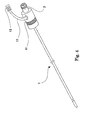
- FIG 4 is a perspective view of the outlook of an embodiment of the terminal instrument, microwave surgery electrode 1.
- the installed cell 7 and the protective resistor 9, both illustrated in Figure 1 are placed inside the handle 41 of the microwave surgery electrode 1.
- From the lateral surface of the handle 41 extend the conductive wires 11, at the end of which is attached low voltage terminals 13.
- the high-frequency connector 3 is connected to the end of the predetermined cable which in turn is connected to the apparatus body 1.
- the cable is provided with distal terminals to be connected to the low voltage terminals 13 and proximal terminals connected to the distal terminals via conductive wires through the cable.
- connection is established between the installed cell 7 and the allowable-length-of-use-setting/discharging section 33.
- the low voltage terminals 13 are provided as a separate part from the high-frequency connector 3 and exposed outside. However, they may be formed into an integral connector.
- the present invention enables to provide a, medical instrument and medical apparatus equipped with it for microwave surgery, electric knife surgery, laser knife surgery, argon beam coagulation, etc., wherein the medical instrument is made so that it can substantially force itself to be disposed of after use through restricting, without adversely affecting its quality or safety of the apparatus, the length of time during which the use of the medical instrument is allowed.
Landscapes
- Health & Medical Sciences (AREA)
- Surgery (AREA)
- Life Sciences & Earth Sciences (AREA)
- Medical Informatics (AREA)
- Animal Behavior & Ethology (AREA)
- Engineering & Computer Science (AREA)
- Biomedical Technology (AREA)
- Heart & Thoracic Surgery (AREA)
- Nuclear Medicine, Radiotherapy & Molecular Imaging (AREA)
- Molecular Biology (AREA)
- Otolaryngology (AREA)
- General Health & Medical Sciences (AREA)
- Public Health (AREA)
- Veterinary Medicine (AREA)
- Surgical Instruments (AREA)
- Laser Surgery Devices (AREA)
- Endoscopes (AREA)
- Electrotherapy Devices (AREA)
- Orthopedics, Nursing, And Contraception (AREA)
Abstract
Description
Claims (13)
- A medical apparatus comprising:an apparatus body (21) having a terminal-output-generating section (27) which generates a predetermined terminal output which may be electric or electromagnetic output and a primary control section (23) which sends an output command to make the terminal-output-generating section (27) generate terminal output, anda terminal instrument which is removably connected via a cable to the terminal-output-generating section (27) and operates as predetermined while receiving the terminal output wherein:(1) the terminal instrument is provided with an installed cell (7) of predetermined capacity and further provided with terminals (13) respectively extending from the both poles of the installed cell (7) and electrically connected via a cable to respective cell-voltage-input terminals (31) on the apparatus body (21), and(2) the apparatus body (21) is provided with(a) an allowable-length-of-use-setting/discharging section (33) and an extension-of-time-setting section (25) both of which operate upon receipt of the output command from the primary control section (23), as well as with a comparison-and-determination section (35), a standard-voltage-setting section (37) which provides the comparison-and-determination section (35) with standard-voltage information to be referred, and an alarm-generating section (39), wherein:(b) the allowable-length-of use-setting/discharging section (33) is so constructed that it, upon receipt of the output command, provides electrical connection between the cell-voltage-input terminals via a predetermined resistor (9) to form a closed circuit to discharge the installed cell (7) and send a voltage-information output corresponding to the electromotive force of the installed cell, which is derived based on the voltage between two points within the circuit, to the comparison-and-determination section (35),(c) the comparison-and-determination section (35) is so constructed that it compares the voltage-information output with the standard-voltage information received from the standard-voltage-setting section (37) and determines whether the electromotive force of the installed cell (7) is on or above the standard level or it has fallen below the standard level, and transmits the result signal to the extension-of-time-setting section (25) and the alarm-generating section (39),(d) the extension-of-time-setting section (25) is so constructed that it, upon receipt of the signal from the comparison-and-determination section (35), transmits the output command received from the primary control section (23) to the terminal-output-generating section (27) if the electromotive force of the installed cell (7) is on or above the standard level but can block the output command if the electromotive force of the installed cell is below the standard level,(e) the alarm-generating section (39) is so constructed that it, corresponding to the resulting signal received from the comparison-and-determination section (35), generates an alarm to indicate the result if the electromotive force of the installed cell (7) is lower than the standard level, and(f) the allowable-length-of-use-setting/discharging section (33) is so constructed that it keeps discharging the installed cell (7) while the output command from the primary control section (23) is transmitted to the terminal-output-generating section (27) and the terminal-output-generating section is generating terminal output.
- The medical apparatus of claim 1 further characterized in that:(g) the extension-of-time-setting section is so constructed that it, while the output command from the primary control section (25) is transmitted to the terminal-output-generating section and the terminal-output-generating section is thereby generating terminal output, continually sends the voltage-information output corresponding to the electromotive force of the installed cell to the comparison-and-determination section,(h) the comparison-and-determination section (35) is so constructed that it compares the continually received voltage-information output with the standard-voltage information received from the standard-voltage-setting section, thereby continually determines whether the electromotive force of the installed cell is on or above the standard level or has come down below the standard level, and transmits the result signal to the extension-of-time-setting section and the alarm-generating section,(i) the extension-of-time-setting section (25) is so constructed that it, upon receipt of the signal in (h), continues to transmit the output command received from the primary control section to the terminal-output-generating section if the electromotive force of the installed cell is on or above the standard level, but can block the output command if the electromotive force of the installed cell has come down below the standard level, and(j) the alarm-generating section (39) is so constructed that it, corresponding to the signal in (h), can generate an alarm indicating when the electromotive force of the installed cell has come down below the standard revel.
- The medical apparatus of claim 2 further characterized in that the extension-of-time-setting section (25) is provided with a timer mechanism which is turned on when the electromotive force of the installed cell (7) has come down below the standard level in (h), and that the primary control section (23), the allowable-length-of-use-setting/discharging section (33), the comparison-and-determination section (35) and extension-of-time-setting section (25) are mutually associated in such a manner that the output command being received from the primary control section (23) is transmitted to the terminal-output-generating section (27) without being blocked until the term set by the timer mechanism has lapsed.
- The medical apparatus of claim 2 further characterized in that the primary control section, the allowable-length-of-use-setting/discharging section (33), the comparison-and-determination section (35) and extension-of-time-setting section (25) are mutually associated in such a manner that, after the electromotive force of the installed cell (7) has come down below the standard level in (h), the output command being received from the primary control section (23) is transmitted to the terminal-output-generating section (27) without being blocked until the output command is once halted.
- The medical apparatus of claim 3 further characterized in that the primary control section, the allowable-length-of-use-setting/ discharging section, the comparison-and-determination section (35) and the extension-of-time-setting section (25) are mutually associated in such a manner that, even after the term set by the timer mechanism has lapsed, the output command being received from the primary control section (23) is transmitted to the terminal-output-generating section without being blocked until the output command is once halted.
- The medical apparatus of one of claims 1 to 5 further comprises a checking mechanism so constructed that it, when the output command is not generated, sends to the comparison-and-determination section (35) a voltage-information output corresponding to the electromotive force of the installed cell (7) derived based on the voltage between the cell-voltage-input terminals without causing substantial discharge of the installed cell.
- The medical apparatus of claim 1 which is an apparatus for microwave surgery, electric knife surgery, laser knife surgery or argon beam coagulation.
- The medical apparatus of claim 6 which is apparatus for microwave surgery, electric knife surgery, laser knife surgery or argon beam coagulation.
- The apparatus body of the medical apparatus as defined in one of claims 1 to 5.
- The medical apparatus of claim 1 or 6 wherein the installed cell is a silver oxide cell.
- A medical terminal instrument of the medical apparatus as defined in one of the claims 1 to 6, wherein said instrument is adapted to operate while receiving from said apparatus body (21) a terminal output which may be electric or electromagnetic output and being provided with an installed cell (7) of predetermined capacity and further being provided with terminals (13) respectively extending from the both poles of the installed cell and being electrically connectable via a cable to respective cell-voltage-input terminals (31) on the apparatus body (21).
- The terminal instrument of claim 11 which is a terminal instrument for apparatus for microwave surgery, electric knife surgery, laser knife surgery, or argon beam coagulation.
- The terminal instrument of claims 11 or 12 wherein the installed cell (7) is a silver oxide cell.
Applications Claiming Priority (3)
| Application Number | Priority Date | Filing Date | Title |
|---|---|---|---|
| JP28750398A JP4142173B2 (en) | 1998-10-09 | 1998-10-09 | Disposable medical device and medical device incorporating the same |
| JP28750398 | 1998-10-09 | ||
| PCT/JP1999/005526 WO2000021448A1 (en) | 1998-10-09 | 1999-10-06 | Disposable medical instrument and medical device incorporating the instrument |
Publications (3)
| Publication Number | Publication Date |
|---|---|
| EP1038504A1 EP1038504A1 (en) | 2000-09-27 |
| EP1038504A4 EP1038504A4 (en) | 2001-11-21 |
| EP1038504B1 true EP1038504B1 (en) | 2005-03-09 |
Family
ID=17718192
Family Applications (1)
| Application Number | Title | Priority Date | Filing Date |
|---|---|---|---|
| EP99970308A Expired - Lifetime EP1038504B1 (en) | 1998-10-09 | 1999-10-06 | Disposable medical instrument and medical device incorporating the instrument |
Country Status (6)
| Country | Link |
|---|---|
| US (1) | US6428535B1 (en) |
| EP (1) | EP1038504B1 (en) |
| JP (1) | JP4142173B2 (en) |
| AT (1) | ATE290342T1 (en) |
| DE (1) | DE69924094T2 (en) |
| WO (1) | WO2000021448A1 (en) |
Families Citing this family (23)
| Publication number | Priority date | Publication date | Assignee | Title |
|---|---|---|---|---|
| JP3652283B2 (en) * | 2000-11-14 | 2005-05-25 | オリンパス株式会社 | Battery-powered power supply for endoscope |
| US8361067B2 (en) | 2002-09-30 | 2013-01-29 | Relievant Medsystems, Inc. | Methods of therapeutically heating a vertebral body to treat back pain |
| US8613744B2 (en) | 2002-09-30 | 2013-12-24 | Relievant Medsystems, Inc. | Systems and methods for navigating an instrument through bone |
| US7258690B2 (en) | 2003-03-28 | 2007-08-21 | Relievant Medsystems, Inc. | Windowed thermal ablation probe |
| US6907884B2 (en) | 2002-09-30 | 2005-06-21 | Depay Acromed, Inc. | Method of straddling an intraosseous nerve |
| WO2005105212A1 (en) * | 2004-04-30 | 2005-11-10 | Olympus Corporation | Energy irradiation device and energy irradiation method |
| US8353906B2 (en) * | 2005-08-01 | 2013-01-15 | Ceramatec, Inc. | Electrochemical probe and method for in situ treatment of a tissue |
| US9186200B2 (en) * | 2006-01-24 | 2015-11-17 | Covidien Ag | System and method for tissue sealing |
| US10028753B2 (en) | 2008-09-26 | 2018-07-24 | Relievant Medsystems, Inc. | Spine treatment kits |
| JP5688022B2 (en) | 2008-09-26 | 2015-03-25 | リリーバント メドシステムズ、インコーポレイテッド | System and method for guiding an instrument through the interior of a bone |
| US8632525B2 (en) * | 2010-09-17 | 2014-01-21 | Ethicon Endo-Surgery, Inc. | Power control arrangements for surgical instruments and batteries |
| JP5734631B2 (en) * | 2010-12-02 | 2015-06-17 | オリンパス株式会社 | Surgery support system |
| US10390877B2 (en) | 2011-12-30 | 2019-08-27 | Relievant Medsystems, Inc. | Systems and methods for treating back pain |
| US10588691B2 (en) | 2012-09-12 | 2020-03-17 | Relievant Medsystems, Inc. | Radiofrequency ablation of tissue within a vertebral body |
| US9265972B2 (en) | 2012-09-24 | 2016-02-23 | Olympus Corporation | Ultrasonic treatment device |
| AU2013337680B2 (en) | 2012-11-05 | 2019-04-18 | Relievant Medsystems, Inc. | Systems and methods for creating curved paths through bone and modulating nerves within the bone |
| US9724151B2 (en) | 2013-08-08 | 2017-08-08 | Relievant Medsystems, Inc. | Modulating nerves within bone using bone fasteners |
| WO2015183880A1 (en) * | 2014-05-27 | 2015-12-03 | Koninklijke Philips N.V. | Self-authenticating intravascular device and associated devices, systems, and methods |
| WO2021050767A1 (en) | 2019-09-12 | 2021-03-18 | Relievant Medsystems, Inc. | Systems and methods for tissue modulation |
| AU2021306313A1 (en) | 2020-07-10 | 2023-03-02 | Relievant Medsystems, Inc. | Vertebral denervation in conjunction with vertebral fusion |
| US12082876B1 (en) | 2020-09-28 | 2024-09-10 | Relievant Medsystems, Inc. | Introducer drill |
| EP4268150A4 (en) | 2020-12-22 | 2024-12-18 | Relievant Medsystems, Inc. | PREDICTION OF CANDIDATES FOR SPINAL NEUROMODULATION |
| US12433668B1 (en) | 2021-11-08 | 2025-10-07 | Relievant Medsystems, Inc. | Impedance stoppage mitigation during radiofrequency tissue ablation procedures |
Family Cites Families (12)
| Publication number | Priority date | Publication date | Assignee | Title |
|---|---|---|---|---|
| JPS62139643A (en) * | 1985-12-13 | 1987-06-23 | オリンパス光学工業株式会社 | Discharge stone destructing apparatus |
| JP2807249B2 (en) * | 1989-02-15 | 1998-10-08 | 株式会社東芝 | Stone crushing equipment |
| US5359993A (en) * | 1992-12-31 | 1994-11-01 | Symbiosis Corporation | Apparatus for counting the number of times a medical instrument has been used |
| JPH04323571A (en) * | 1991-04-22 | 1992-11-12 | Olympus Optical Co Ltd | Measuring device for operating time of consumable component |
| JP3065174B2 (en) * | 1992-06-02 | 2000-07-12 | 株式会社トキメック | Combustion appliance usage time detection device |
| US5275166A (en) * | 1992-11-16 | 1994-01-04 | Ethicon, Inc. | Method and apparatus for performing ultrasonic assisted surgical procedures |
| JPH0795982A (en) | 1993-04-19 | 1995-04-11 | Olympus Optical Co Ltd | Disposable medical device |
| US5782749A (en) * | 1994-05-10 | 1998-07-21 | Riza; Erol D. | Laparoscopic surgical instrument with adjustable grip |
| US5518927A (en) * | 1994-08-17 | 1996-05-21 | Steris Corporation | Instrument sterilation life-span indicator |
| JPH08275957A (en) * | 1995-04-07 | 1996-10-22 | Olympus Optical Co Ltd | Electric surgical operation device |
| US5817092A (en) * | 1995-11-09 | 1998-10-06 | Radio Therapeutics Corporation | Apparatus, system and method for delivering radio frequency energy to a treatment site |
| US5792138A (en) * | 1996-02-22 | 1998-08-11 | Apollo Camera, Llc | Cordless bipolar electrocautery unit with automatic power control |
-
1998
- 1998-10-09 JP JP28750398A patent/JP4142173B2/en not_active Expired - Fee Related
-
1999
- 1999-10-06 US US09/555,966 patent/US6428535B1/en not_active Expired - Fee Related
- 1999-10-06 EP EP99970308A patent/EP1038504B1/en not_active Expired - Lifetime
- 1999-10-06 WO PCT/JP1999/005526 patent/WO2000021448A1/en not_active Ceased
- 1999-10-06 AT AT99970308T patent/ATE290342T1/en not_active IP Right Cessation
- 1999-10-06 DE DE69924094T patent/DE69924094T2/en not_active Expired - Fee Related
Also Published As
| Publication number | Publication date |
|---|---|
| EP1038504A1 (en) | 2000-09-27 |
| US6428535B1 (en) | 2002-08-06 |
| EP1038504A4 (en) | 2001-11-21 |
| JP2000107189A (en) | 2000-04-18 |
| WO2000021448A1 (en) | 2000-04-20 |
| ATE290342T1 (en) | 2005-03-15 |
| JP4142173B2 (en) | 2008-08-27 |
| DE69924094D1 (en) | 2005-04-14 |
| DE69924094T2 (en) | 2005-07-14 |
Similar Documents
| Publication | Publication Date | Title |
|---|---|---|
| US6428535B1 (en) | Disposable medical instrument and medical device incorporating the instrument | |
| US7879032B1 (en) | Disposable electrosurgical handpiece | |
| US20020082593A1 (en) | Heating treatment system | |
| US20070055223A1 (en) | Methods and apparatus for hemostasis following arterial catheterization | |
| US5383874A (en) | Systems for identifying catheters and monitoring their use | |
| US20130006239A1 (en) | Electrosurgical systems and methods | |
| JP2002153481A (en) | Medical treatment system, treating tool and controller for treating tool | |
| WO1999049313A1 (en) | Multi-use sensor having a controllable number of measurement cycles | |
| RU2701135C2 (en) | Self-evaluating intravascular device and related devices, systems and methods | |
| JPH0368695B2 (en) | ||
| JP2005534069A (en) | Laser system | |
| US8755420B2 (en) | Failure protection apparatus and system | |
| US20050239349A9 (en) | Medical products with limited use aspect | |
| CN101247767B (en) | Safety equipment for high frequency surgical instruments | |
| US20030233088A1 (en) | Resectscope apparatus | |
| US7236827B2 (en) | Single-use medical device | |
| CN117883177A (en) | RF energy generating device and RF energy therapy system | |
| JPS61128959A (en) | Cauterization hemostatic apparatus | |
| JP4421444B2 (en) | High frequency power supply for medical devices | |
| JPH09173349A (en) | Solidifying device for medical treatment | |
| JP7580547B2 (en) | Electrical medical device control system, power supply unit, relay device, and power supply method | |
| JPS61288852A (en) | Cauterizing hemostatic apparatus | |
| CN214857376U (en) | Syringe mis-push alarm system and device | |
| JPH0458980B2 (en) | ||
| JPS61128960A (en) | Cauterization hemostatic apparatus |
Legal Events
| Date | Code | Title | Description |
|---|---|---|---|
| PUAI | Public reference made under article 153(3) epc to a published international application that has entered the european phase |
Free format text: ORIGINAL CODE: 0009012 |
|
| 17P | Request for examination filed |
Effective date: 20000608 |
|
| AK | Designated contracting states |
Kind code of ref document: A1 Designated state(s): AT BE CH CY DE DK ES FI FR GB GR IE IT LI LU MC NL PT SE |
|
| A4 | Supplementary search report drawn up and despatched |
Effective date: 20011008 |
|
| AK | Designated contracting states |
Kind code of ref document: A4 Designated state(s): AT BE CH CY DE DK ES FI FR GB GR IE IT LI LU MC NL PT SE |
|
| RIC1 | Information provided on ipc code assigned before grant |
Free format text: 7A 61B 17/39 A |
|
| GRAP | Despatch of communication of intention to grant a patent |
Free format text: ORIGINAL CODE: EPIDOSNIGR1 |
|
| RIC1 | Information provided on ipc code assigned before grant |
Ipc: 7A 61B 18/00 A |
|
| RIC1 | Information provided on ipc code assigned before grant |
Ipc: 7A 61B 18/00 A |
|
| GRAS | Grant fee paid |
Free format text: ORIGINAL CODE: EPIDOSNIGR3 |
|
| GRAA | (expected) grant |
Free format text: ORIGINAL CODE: 0009210 |
|
| RAP1 | Party data changed (applicant data changed or rights of an application transferred) |
Owner name: ALFRESA PHARMA CORPORATION |
|
| AK | Designated contracting states |
Kind code of ref document: B1 Designated state(s): AT BE CH CY DE DK ES FI FR GB GR IE IT LI LU MC NL PT SE |
|
| PG25 | Lapsed in a contracting state [announced via postgrant information from national office to epo] |
Ref country code: NL Free format text: LAPSE BECAUSE OF FAILURE TO SUBMIT A TRANSLATION OF THE DESCRIPTION OR TO PAY THE FEE WITHIN THE PRESCRIBED TIME-LIMIT Effective date: 20050309 Ref country code: LI Free format text: LAPSE BECAUSE OF FAILURE TO SUBMIT A TRANSLATION OF THE DESCRIPTION OR TO PAY THE FEE WITHIN THE PRESCRIBED TIME-LIMIT Effective date: 20050309 Ref country code: IT Free format text: LAPSE BECAUSE OF FAILURE TO SUBMIT A TRANSLATION OF THE DESCRIPTION OR TO PAY THE FEE WITHIN THE PRESCRIBED TIME-LIMIT;WARNING: LAPSES OF ITALIAN PATENTS WITH EFFECTIVE DATE BEFORE 2007 MAY HAVE OCCURRED AT ANY TIME BEFORE 2007. THE CORRECT EFFECTIVE DATE MAY BE DIFFERENT FROM THE ONE RECORDED. Effective date: 20050309 Ref country code: FI Free format text: LAPSE BECAUSE OF FAILURE TO SUBMIT A TRANSLATION OF THE DESCRIPTION OR TO PAY THE FEE WITHIN THE PRESCRIBED TIME-LIMIT Effective date: 20050309 Ref country code: CH Free format text: LAPSE BECAUSE OF FAILURE TO SUBMIT A TRANSLATION OF THE DESCRIPTION OR TO PAY THE FEE WITHIN THE PRESCRIBED TIME-LIMIT Effective date: 20050309 Ref country code: BE Free format text: LAPSE BECAUSE OF FAILURE TO SUBMIT A TRANSLATION OF THE DESCRIPTION OR TO PAY THE FEE WITHIN THE PRESCRIBED TIME-LIMIT Effective date: 20050309 Ref country code: AT Free format text: LAPSE BECAUSE OF FAILURE TO SUBMIT A TRANSLATION OF THE DESCRIPTION OR TO PAY THE FEE WITHIN THE PRESCRIBED TIME-LIMIT Effective date: 20050309 |
|
| RAP1 | Party data changed (applicant data changed or rights of an application transferred) |
Owner name: ALFRESA PHARMA CORPORATION |
|
| REG | Reference to a national code |
Ref country code: GB Ref legal event code: FG4D |
|
| REG | Reference to a national code |
Ref country code: CH Ref legal event code: EP |
|
| REG | Reference to a national code |
Ref country code: IE Ref legal event code: FG4D |
|
| REF | Corresponds to: |
Ref document number: 69924094 Country of ref document: DE Date of ref document: 20050414 Kind code of ref document: P |
|
| PG25 | Lapsed in a contracting state [announced via postgrant information from national office to epo] |
Ref country code: GR Free format text: LAPSE BECAUSE OF FAILURE TO SUBMIT A TRANSLATION OF THE DESCRIPTION OR TO PAY THE FEE WITHIN THE PRESCRIBED TIME-LIMIT Effective date: 20050609 Ref country code: DK Free format text: LAPSE BECAUSE OF FAILURE TO SUBMIT A TRANSLATION OF THE DESCRIPTION OR TO PAY THE FEE WITHIN THE PRESCRIBED TIME-LIMIT Effective date: 20050609 |
|
| PG25 | Lapsed in a contracting state [announced via postgrant information from national office to epo] |
Ref country code: ES Free format text: LAPSE BECAUSE OF FAILURE TO SUBMIT A TRANSLATION OF THE DESCRIPTION OR TO PAY THE FEE WITHIN THE PRESCRIBED TIME-LIMIT Effective date: 20050620 |
|
| NLV1 | Nl: lapsed or annulled due to failure to fulfill the requirements of art. 29p and 29m of the patents act | ||
| PG25 | Lapsed in a contracting state [announced via postgrant information from national office to epo] |
Ref country code: PT Free format text: LAPSE BECAUSE OF FAILURE TO SUBMIT A TRANSLATION OF THE DESCRIPTION OR TO PAY THE FEE WITHIN THE PRESCRIBED TIME-LIMIT Effective date: 20050907 |
|
| REG | Reference to a national code |
Ref country code: CH Ref legal event code: PL |
|
| PGFP | Annual fee paid to national office [announced via postgrant information from national office to epo] |
Ref country code: GB Payment date: 20051005 Year of fee payment: 7 |
|
| PG25 | Lapsed in a contracting state [announced via postgrant information from national office to epo] |
Ref country code: IE Free format text: LAPSE BECAUSE OF NON-PAYMENT OF DUE FEES Effective date: 20051006 Ref country code: CY Free format text: LAPSE BECAUSE OF FAILURE TO SUBMIT A TRANSLATION OF THE DESCRIPTION OR TO PAY THE FEE WITHIN THE PRESCRIBED TIME-LIMIT Effective date: 20051006 |
|
| PGFP | Annual fee paid to national office [announced via postgrant information from national office to epo] |
Ref country code: FR Payment date: 20051010 Year of fee payment: 7 |
|
| PG25 | Lapsed in a contracting state [announced via postgrant information from national office to epo] |
Ref country code: MC Free format text: LAPSE BECAUSE OF NON-PAYMENT OF DUE FEES Effective date: 20051031 Ref country code: LU Free format text: LAPSE BECAUSE OF NON-PAYMENT OF DUE FEES Effective date: 20051031 |
|
| PGFP | Annual fee paid to national office [announced via postgrant information from national office to epo] |
Ref country code: DE Payment date: 20051031 Year of fee payment: 7 |
|
| PLBE | No opposition filed within time limit |
Free format text: ORIGINAL CODE: 0009261 |
|
| STAA | Information on the status of an ep patent application or granted ep patent |
Free format text: STATUS: NO OPPOSITION FILED WITHIN TIME LIMIT |
|
| ET | Fr: translation filed | ||
| 26N | No opposition filed |
Effective date: 20051212 |
|
| REG | Reference to a national code |
Ref country code: IE Ref legal event code: MM4A |
|
| PG25 | Lapsed in a contracting state [announced via postgrant information from national office to epo] |
Ref country code: DE Free format text: LAPSE BECAUSE OF NON-PAYMENT OF DUE FEES Effective date: 20070501 |
|
| GBPC | Gb: european patent ceased through non-payment of renewal fee |
Effective date: 20061006 |
|
| REG | Reference to a national code |
Ref country code: FR Ref legal event code: ST Effective date: 20070629 |
|
| PG25 | Lapsed in a contracting state [announced via postgrant information from national office to epo] |
Ref country code: GB Free format text: LAPSE BECAUSE OF NON-PAYMENT OF DUE FEES Effective date: 20061006 |
|
| PG25 | Lapsed in a contracting state [announced via postgrant information from national office to epo] |
Ref country code: SE Free format text: LAPSE BECAUSE OF FAILURE TO SUBMIT A TRANSLATION OF THE DESCRIPTION OR TO PAY THE FEE WITHIN THE PRESCRIBED TIME-LIMIT Effective date: 20050609 |
|
| PG25 | Lapsed in a contracting state [announced via postgrant information from national office to epo] |
Ref country code: FR Free format text: LAPSE BECAUSE OF NON-PAYMENT OF DUE FEES Effective date: 20061031 |