EP1037735B1 - Mold heater startup method - Google Patents
Mold heater startup method Download PDFInfo
- Publication number
- EP1037735B1 EP1037735B1 EP98963001A EP98963001A EP1037735B1 EP 1037735 B1 EP1037735 B1 EP 1037735B1 EP 98963001 A EP98963001 A EP 98963001A EP 98963001 A EP98963001 A EP 98963001A EP 1037735 B1 EP1037735 B1 EP 1037735B1
- Authority
- EP
- European Patent Office
- Prior art keywords
- zone
- zones
- mold
- heaters
- mass
- Prior art date
- Legal status (The legal status is an assumption and is not a legal conclusion. Google has not performed a legal analysis and makes no representation as to the accuracy of the status listed.)
- Expired - Lifetime
Links
- 238000000034 method Methods 0.000 title claims abstract description 39
- 239000004033 plastic Substances 0.000 claims abstract description 18
- 238000010438 heat treatment Methods 0.000 claims description 16
- 238000001746 injection moulding Methods 0.000 claims description 8
- 238000012544 monitoring process Methods 0.000 claims description 6
- 230000008859 change Effects 0.000 claims description 3
- 238000005259 measurement Methods 0.000 claims description 2
- 238000012163 sequencing technique Methods 0.000 abstract description 13
- 239000000463 material Substances 0.000 abstract description 12
- 230000015556 catabolic process Effects 0.000 abstract description 10
- 238000006731 degradation reaction Methods 0.000 abstract description 10
- 238000002347 injection Methods 0.000 description 9
- 239000007924 injection Substances 0.000 description 9
- 238000005297 material degradation process Methods 0.000 description 7
- 230000000630 rising effect Effects 0.000 description 6
- 238000000465 moulding Methods 0.000 description 5
- 238000007789 sealing Methods 0.000 description 5
- 230000008569 process Effects 0.000 description 4
- 238000004891 communication Methods 0.000 description 3
- 238000010276 construction Methods 0.000 description 3
- 230000002035 prolonged effect Effects 0.000 description 3
- 230000004913 activation Effects 0.000 description 2
- 230000002411 adverse Effects 0.000 description 2
- 230000000694 effects Effects 0.000 description 2
- 238000005485 electric heating Methods 0.000 description 2
- 239000012530 fluid Substances 0.000 description 2
- 230000007246 mechanism Effects 0.000 description 2
- 238000010521 absorption reaction Methods 0.000 description 1
- 230000003213 activating effect Effects 0.000 description 1
- WYTGDNHDOZPMIW-RCBQFDQVSA-N alstonine Natural products C1=CC2=C3C=CC=CC3=NC2=C2N1C[C@H]1[C@H](C)OC=C(C(=O)OC)[C@H]1C2 WYTGDNHDOZPMIW-RCBQFDQVSA-N 0.000 description 1
- 230000004075 alteration Effects 0.000 description 1
- 238000013459 approach Methods 0.000 description 1
- 238000013528 artificial neural network Methods 0.000 description 1
- 230000000712 assembly Effects 0.000 description 1
- 238000000429 assembly Methods 0.000 description 1
- 239000002826 coolant Substances 0.000 description 1
- 238000001514 detection method Methods 0.000 description 1
- 230000006872 improvement Effects 0.000 description 1
- 238000012423 maintenance Methods 0.000 description 1
- 238000004519 manufacturing process Methods 0.000 description 1
- 239000000155 melt Substances 0.000 description 1
- 238000012986 modification Methods 0.000 description 1
- 230000004048 modification Effects 0.000 description 1
- 230000002028 premature Effects 0.000 description 1
- 239000007787 solid Substances 0.000 description 1
- 230000000153 supplemental effect Effects 0.000 description 1
- 229920001169 thermoplastic Polymers 0.000 description 1
- 239000004416 thermosoftening plastic Substances 0.000 description 1
- 230000000007 visual effect Effects 0.000 description 1
Images


Classifications
-
- B—PERFORMING OPERATIONS; TRANSPORTING
- B29—WORKING OF PLASTICS; WORKING OF SUBSTANCES IN A PLASTIC STATE IN GENERAL
- B29C—SHAPING OR JOINING OF PLASTICS; SHAPING OF MATERIAL IN A PLASTIC STATE, NOT OTHERWISE PROVIDED FOR; AFTER-TREATMENT OF THE SHAPED PRODUCTS, e.g. REPAIRING
- B29C45/00—Injection moulding, i.e. forcing the required volume of moulding material through a nozzle into a closed mould; Apparatus therefor
- B29C45/17—Component parts, details or accessories; Auxiliary operations
- B29C45/76—Measuring, controlling or regulating
- B29C45/78—Measuring, controlling or regulating of temperature
-
- B—PERFORMING OPERATIONS; TRANSPORTING
- B29—WORKING OF PLASTICS; WORKING OF SUBSTANCES IN A PLASTIC STATE IN GENERAL
- B29C—SHAPING OR JOINING OF PLASTICS; SHAPING OF MATERIAL IN A PLASTIC STATE, NOT OTHERWISE PROVIDED FOR; AFTER-TREATMENT OF THE SHAPED PRODUCTS, e.g. REPAIRING
- B29C45/00—Injection moulding, i.e. forcing the required volume of moulding material through a nozzle into a closed mould; Apparatus therefor
- B29C45/17—Component parts, details or accessories; Auxiliary operations
- B29C45/26—Moulds
- B29C45/27—Sprue channels ; Runner channels or runner nozzles
- B29C45/2737—Heating or cooling means therefor
- B29C2045/274—Thermocouples or heat sensors
-
- B—PERFORMING OPERATIONS; TRANSPORTING
- B29—WORKING OF PLASTICS; WORKING OF SUBSTANCES IN A PLASTIC STATE IN GENERAL
- B29C—SHAPING OR JOINING OF PLASTICS; SHAPING OF MATERIAL IN A PLASTIC STATE, NOT OTHERWISE PROVIDED FOR; AFTER-TREATMENT OF THE SHAPED PRODUCTS, e.g. REPAIRING
- B29C2945/00—Indexing scheme relating to injection moulding, i.e. forcing the required volume of moulding material through a nozzle into a closed mould
- B29C2945/76—Measuring, controlling or regulating
- B29C2945/76003—Measured parameter
- B29C2945/7604—Temperature
-
- B—PERFORMING OPERATIONS; TRANSPORTING
- B29—WORKING OF PLASTICS; WORKING OF SUBSTANCES IN A PLASTIC STATE IN GENERAL
- B29C—SHAPING OR JOINING OF PLASTICS; SHAPING OF MATERIAL IN A PLASTIC STATE, NOT OTHERWISE PROVIDED FOR; AFTER-TREATMENT OF THE SHAPED PRODUCTS, e.g. REPAIRING
- B29C2945/00—Indexing scheme relating to injection moulding, i.e. forcing the required volume of moulding material through a nozzle into a closed mould
- B29C2945/76—Measuring, controlling or regulating
- B29C2945/76177—Location of measurement
- B29C2945/76254—Mould
-
- B—PERFORMING OPERATIONS; TRANSPORTING
- B29—WORKING OF PLASTICS; WORKING OF SUBSTANCES IN A PLASTIC STATE IN GENERAL
- B29C—SHAPING OR JOINING OF PLASTICS; SHAPING OF MATERIAL IN A PLASTIC STATE, NOT OTHERWISE PROVIDED FOR; AFTER-TREATMENT OF THE SHAPED PRODUCTS, e.g. REPAIRING
- B29C2945/00—Indexing scheme relating to injection moulding, i.e. forcing the required volume of moulding material through a nozzle into a closed mould
- B29C2945/76—Measuring, controlling or regulating
- B29C2945/76494—Controlled parameter
- B29C2945/76525—Electric current or voltage
-
- B—PERFORMING OPERATIONS; TRANSPORTING
- B29—WORKING OF PLASTICS; WORKING OF SUBSTANCES IN A PLASTIC STATE IN GENERAL
- B29C—SHAPING OR JOINING OF PLASTICS; SHAPING OF MATERIAL IN A PLASTIC STATE, NOT OTHERWISE PROVIDED FOR; AFTER-TREATMENT OF THE SHAPED PRODUCTS, e.g. REPAIRING
- B29C2945/00—Indexing scheme relating to injection moulding, i.e. forcing the required volume of moulding material through a nozzle into a closed mould
- B29C2945/76—Measuring, controlling or regulating
- B29C2945/76655—Location of control
- B29C2945/76792—Auxiliary devices
-
- B—PERFORMING OPERATIONS; TRANSPORTING
- B29—WORKING OF PLASTICS; WORKING OF SUBSTANCES IN A PLASTIC STATE IN GENERAL
- B29C—SHAPING OR JOINING OF PLASTICS; SHAPING OF MATERIAL IN A PLASTIC STATE, NOT OTHERWISE PROVIDED FOR; AFTER-TREATMENT OF THE SHAPED PRODUCTS, e.g. REPAIRING
- B29C2945/00—Indexing scheme relating to injection moulding, i.e. forcing the required volume of moulding material through a nozzle into a closed mould
- B29C2945/76—Measuring, controlling or regulating
- B29C2945/76929—Controlling method
- B29C2945/76939—Using stored or historical data sets
- B29C2945/76943—Using stored or historical data sets compare with thresholds
-
- B—PERFORMING OPERATIONS; TRANSPORTING
- B29—WORKING OF PLASTICS; WORKING OF SUBSTANCES IN A PLASTIC STATE IN GENERAL
- B29C—SHAPING OR JOINING OF PLASTICS; SHAPING OF MATERIAL IN A PLASTIC STATE, NOT OTHERWISE PROVIDED FOR; AFTER-TREATMENT OF THE SHAPED PRODUCTS, e.g. REPAIRING
- B29C45/00—Injection moulding, i.e. forcing the required volume of moulding material through a nozzle into a closed mould; Apparatus therefor
- B29C45/17—Component parts, details or accessories; Auxiliary operations
- B29C45/26—Moulds
- B29C45/27—Sprue channels ; Runner channels or runner nozzles
- B29C45/2737—Heating or cooling means therefor
- B29C45/2738—Heating or cooling means therefor specially adapted for manifolds
Definitions
- the present invention relates generally to molds used in injection molding machines and, more particularly, to a method for sequencing the startup of electric heating elements used in such molds.
- the molds used to form injection molded products often include heating elements to control the temperature of certain portions (zones) of the mold.
- heaters are used in "hot runner” systems to provide a temperature controlled flow path for the plastic melt that travels from the injection unit of the molding machine to the mold cavity.
- Such systems typically include a manifold that supplies a number of nozzles that each supply melt to a mold cavity.
- Multiple heaters are strategically positioned throughout the mold and/or hot runner system to maintain the proper temperature and thereby ensure that good quality melt is used to form each part.
- the thermal mass associated with each heater can vary considerably. If the heater zones are not properly sequenced at startup, there can be excessive wear on associated mechanical elements of the system (due to differences in thermal expansion), degradation of plastic within the mold, lengthy mold prep time, and unsuitable total current draw by the system.
- An alternative to simultaneous startup is manual sequencing of the heaters.
- the operator begins heater startup by switching electrical power to the heaters associated with the largest thermal masses (as determined by the operator, the manifolds, for example), allowing them to approach the temperature set point before turning on the heaters in the smaller zones (the nozzles, for example). If there are multiple levels of manifolds, the operator may turn on one level, then the next level and, finally, the nozzles.
- Manual sequencing also allows the operator to extend the total startup time considerably beyond what is actually required by being overly conservative in how the sequence is implemented.
- the operator may turn on the manifold heaters and leave the machine to attend to other matters.
- the manifold may actually be up to heat for some time before the operator returns to turn on the next level of manifold or the nozzles. Since this will extend the time the first level is under heat, it will extend startup time. The danger of material degradation is also present under these circumstances.
- the operator has to monitor the process closely in order to determine when each level in the sequencing is up to heat and when to activate the next level.
- a more automatic method is "uniform" startup where a computerized system monitors the rate of temperature rise of each zone of heating in the system.
- This type of control identifies the zones where the temperature is rising quickly and controls the power to the heaters to slow the rate of temperature increase.
- the computer allows the fast rising zones to reach a certain temperature and then inhibits further heat input, allowing the slower rising zones to "catch up”. This process is continued until the temperatures for the various zones reach their set point.
- the electrical heaters used in the described systems are often hygroscopic, i.e., they absorb moisture from the air and must be "dried out” before full voltage or power is applied. If not properly dried prior to applying full power, the heaters may be permanently damaged.
- manifold heaters are often constructed in such a way that moisture absorption is not a problem, nozzle heaters rarely are. This difference suggests that the manifold heaters may not require dry-out at the onset of the startup procedure, while the heaters for the nozzle zones must always be properly dried out before applying full voltage.
- dry-out of the nozzle heaters does not commence until they are turned on, usually after the manifolds are nearly up to temperature; this further extends startup time. Only the "uniform" method allows for dry-out of all zones during the sequencing. Unfortunately, the "uniform” method also allows for significant rise in heat of the nozzles, resulting in thermal expansion and material degradation, as described above.
- US 5280422 discloses a method and apparatus for calibrating and controlling multiple heaters.
- the multiple heaters are calibrated and controlled by a microcomputer, and a multiplexer of this system.
- the heaters are sequentially sampled and resistance calculated from voltage and current measurements.
- the operator enters a temperature for the calculated resistance to establish a calibrated resistance value.
- the computer energizes and samples each heater to calculate its resistance.
- the computer compares this with a look-up table to determine actual heater temperatures, and based upon these, the computer controls energization of the heaters until set points are achieved.
- an injection molding system including a mold with a heated runner system for supplying plastic melt to a cavity within the mold and a plurality of heating elements associated with the mold and runner system, a method for bringing the mold and runner system to a desired operating temperature comprising the steps of:
- the method of the present invention involves detecting the heater zone having the largest mass, applying heat to that zone, thus allowing that segment of the mold to grow (expand due to temperature rise) unimpeded.
- the heater zones associated with smaller mass are kept at minimal temperatures until the larger zones come up to heat.
- the system is capable of detecting multiple levels of rates of temperature increase and can provide sequential startup of these differing types of thermal loads.
- the operator may also manually program the system to override certain automated sequences in order to guarantee a startup sequence that best minimizes mechanical wear and prevents the degradation of plastic material.
- the mold heater startup sequencing method of the present invention monitors the rate of temperature increase in the various zones to determine the relative thermal mass; i.e., the larger the mass, the slower the temperature increase. The method then applies power to the zones of higher mass to control thermal expansion of the primary mold elements in a way that minimizes wear of the associated mechanical components and sealing elements.
- the heater startup method also minimizes or prevents the degradation of plastic material by reducing the amount of time that the material is subject to high temperatures.
- the disclosed method serves to minimize the amount of time it takes to prepare the molding system for operation while accomplishing the previously noted advantages for system startup.
- the sequencing of power application to large heaters reduces the peak current draw of the system, helping to prevent electrical circuit overloads and peak demand charges from utility companies.
- the apparatus associated with the disclosed method includes suitable microprocessor(s), analog to digital converter(s) and triacs (or other suitable power switching devices) that are operatively coupled to the heaters and corresponding temperature sensors in each zone.
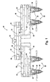
- Fig. 1 illustrates a hot runner system 10 that is used to convey thermoplastic melt from the injection unit of an injection molding machine to multiple mold cavities.
- a "level one" manifold 12 that receives the flow of plastic melt from the injection unit though a nozzle adapter 14.
- the plastic melt is conveyed through conduits 16 in the level one manifold 12 to be received by two "level two" manifolds 18.
- the level two manifolds 18 also include flow passages 20 to convey the melt from the level one manifold 12 to multiple nozzles 22.
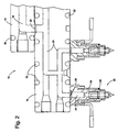
- Each of the nozzles 22 is in communication with a mold cavity in order to convey the plastic melt received from an associated flow passage 20 in the level two manifold 18, through a central passage 24 and into the mold cavity.
- seals 26 are provided at the junction of the passages 16 of the level one manifold 12 with the passages 20 of the level two manifold 18.
- seal rings 28 are provided at the junction of the passages 20 of the level two manifold 18 with the central passages 24 of the nozzles 22.
- the hot runner system 10 is provided with multiple heating elements in order to bring the components (manifolds 12, 18 and nozzles 22) up to a suitable operating temperature (at initial start-up) and maintain the desired temperature of the plastic melt as it is conveyed to the mold.
- the desired operating temperatures are dictated by the type of plastic material used in a given application.
- the level one manifold 12 has two heating elements 30 encircling the flow passage 16.
- the level two manifolds 18 have two sets of serpentine heating elements 32 to supply heat in close proximity to the flow passages 20.
- the manifolds 12, 18 could be fitted with standard cartridge type heaters, rather than the elongated, serpentine elements shown.
- the nozzles 22 are equipped with heating elements 34 that encircle the main body of the nozzles 22 to ensure proper flow through the central passage 24.
- thermocouples positioned to indicate accurately the thermal gradients in the system.
- the level one manifold 12 has thermocouples 36
- the level two manifolds 18 have thermocouples 38
- the nozzles 22 are provided with thermocouples 40.
- the set points for the heaters are initially based on the type of plastic being processed and are adjusted, often by trial and error, to achieve a set of conditions that facilitate continuous operation of the injection molding machine without "hot spots" that can cause material degradation.
- the method of the present invention can be implemented by a control system that uses a single microprocessor (CPU) to monitor and control the temperatures in all heater zones for a particular mold configuration; this is generally referred to as a multiplexed or multi-loop control system.
- CPU microprocessor
- the heater startup method can be included in a modular heater system constructed from multiple single-loop control modules (see Fig. 6) where a communications interface between the modules allows the independent heater zones to communicate with each other so that the desired startup sequence can be implemented. More specifically, in the modular configuration, a neural network or other communication means is utilized to allow each zone to share information with other zones to determine the relative thermal characteristics of the zones. Generally speaking, it is likely that the heater zones of a hot runner system will be broken into two, three or more sets of thermal characteristics. Each set becomes a "level" to be included in the startup sequence. The set with the fastest rate of heat rise characteristics will typically be the zones including nozzle heaters 34. These "fast rising" zones will be the last to be sequenced in all cases.
- Implementation of the method of the present invention begins with all zones being activated in a dry-out mode; i.e., very low voltage (or power). Using feedback generated by appropriate sensors during the initial part of the dry-out mode, the "slow" and "fast" heater zones are identified. More specifically, a large current draw by a particular zone during dry-out would indicate there are high-power heaters in this zone that would be associated with a large thermal mass. Conversely, a low current draw by a particular zone indicates smaller heaters associated with less thermal mass. Alternatively, the determination of slow and fast heater zones can be made more directly by calculating the rate of temperature in the various zones during dry-out; the higher the rate, the "faster” the zone.
- a predetermined voltage is applied to bring that zone to its programmed set point.
- voltage may be applied to multiple zones if no adverse expansion will occur.
- the application of the low (dry-out) voltage is maintained for the "fast” zones until the "slow” zones have all reached their set point temperatures.
- Application of low voltage means that there will only be minimal temperature rise in the "fast” zones to prevent undesirable thermal expansion and degradation of material.
- the heater zones for the nozzles will be released from low voltage (dry-out) when the single set of manifolds reaches a predetermined temperature (often the lower end of the control's proportional or alarm band). With the multiple levels of manifolds, the second level manifold will be released from dry-out when the first level achieves the predetermined temperature; this process is continued until all manifold levels reach the desired set point. Finally, the heaters for the nozzles are activated to bring them up to temperature. Preferably, the system control would allow the operator to input the predetermined (set point) temperatures that trigger the startup of the next level or set of heater zones.
- the method of the present invention could be used in conjunction with the "Mold Heater Moisture Detection and Dry Out Apparatus" disclosed in United States Patent No. 5,039,842 to (a) prevent the application of high voltage or power to a heater if a large amount of ground leakage current was detected and/or (b) shut-off power to a heater if the ground leakage current exceed a preset maximum and cannot be corrected with the application of low voltage.
- microprocessors are used to determine the thermal properties of the zones quickly and automatically.
- the operator could enter the thermal relationship of the zones, if known, into the control system manually via keyboard, touch-screen or other means as known in the art.
- the modules may be programmed using physical switches or jumpers to provide the desired thermal level identification.
- the heater zone sets are displayed on a computer screen or other appropriate readout to provide visual feedback to the operator.
- the operator would then be able to modify the set assignment for each zone, if desired.
- the operator would also be able to enter this information prior to performing an initial startup of the control system.
- control system would allow the operator to save the learned and/or programmed thermal mass relationship of the heater to a storage device, such as hard/floppy disk, or solid state memory devices, such as battery backed RAM, EEPROM, EAROM, or flash ROM.
- a storage device such as hard/floppy disk, or solid state memory devices, such as battery backed RAM, EEPROM, EAROM, or flash ROM.
- the same storage device could also store the set point temperatures used to determine when to sequence startup of the subsequent levels.
- the present invention provides a method of controlling the activation and sequencing of heater zones in molds used in injection molding machines that result in less wear of sealing elements and effectively prevents the degradation of plastic melt due to prolonged exposure to heat.
- the system is capable of detecting multiple levels of rates of temperature increase and can provide sequential startup of these differing types of thermal loads.
- the disclosed method serves to minimize the amount of time it takes to prepare the molding system for operation while accomplishing the previously noted advantages for system startup.
- the sequencing of power application to large heaters reduces the peak current draw of the system, helping to prevent electrical circuit overloads and peak demand charges from utility companies.
- the apparatus associated with the disclosed method includes suitable microprocessor(s), analog to digital converter(s) and triacs (or other suitable power switching devices) that are operatively coupled to the heaters and corresponding temperature sensors in each zone.
- a single zone may include more than one heater or different heater configurations.
- other systems or mechanisms can be used to control the supply of electric power to the heaters.
Landscapes
- Engineering & Computer Science (AREA)
- Manufacturing & Machinery (AREA)
- Mechanical Engineering (AREA)
- Moulds For Moulding Plastics Or The Like (AREA)
- Injection Moulding Of Plastics Or The Like (AREA)
- Mounting, Exchange, And Manufacturing Of Dies (AREA)
- Yarns And Mechanical Finishing Of Yarns Or Ropes (AREA)
- Perforating, Stamping-Out Or Severing By Means Other Than Cutting (AREA)
Abstract
Description
- The present invention relates generally to molds used in injection molding machines and, more particularly, to a method for sequencing the startup of electric heating elements used in such molds.
- The molds used to form injection molded products often include heating elements to control the temperature of certain portions (zones) of the mold. In particular, heaters are used in "hot runner" systems to provide a temperature controlled flow path for the plastic melt that travels from the injection unit of the molding machine to the mold cavity. Such systems typically include a manifold that supplies a number of nozzles that each supply melt to a mold cavity. Multiple heaters are strategically positioned throughout the mold and/or hot runner system to maintain the proper temperature and thereby ensure that good quality melt is used to form each part. However, given the various constraints on the number and location of heating elements, as dictated by a particular mold's construction (e.g., gates, coolant passages, core mechanisms, ejector pins, etc.), the thermal mass associated with each heater can vary considerably. If the heater zones are not properly sequenced at startup, there can be excessive wear on associated mechanical elements of the system (due to differences in thermal expansion), degradation of plastic within the mold, lengthy mold prep time, and unsuitable total current draw by the system.
- Various startup systems have been proposed in the prior art. The simplest method is simultaneous startup of all zones. The molding machine operator implements this method by activating all zones of heat at the same time. The result is that zones with less mass ("fast rising" zones) reach the desired temperature more quickly, resulting in degradation the material while the operator is waiting for the other zones to reach the appropriate temperature. In addition, the time differential in reaching temperature can result in excessive wear of the associated sealing elements because the nozzles (and possibly other manifold components) have expanded in size and apply pressure on the manifold in one direction while the manifold is still expanding in another direction.
- An alternative to simultaneous startup is manual sequencing of the heaters. In this method, the operator begins heater startup by switching electrical power to the heaters associated with the largest thermal masses (as determined by the operator, the manifolds, for example), allowing them to approach the temperature set point before turning on the heaters in the smaller zones (the nozzles, for example). If there are multiple levels of manifolds, the operator may turn on one level, then the next level and, finally, the nozzles.
- Although manual sequencing can be an improvement over simultaneous startup, there are still several drawbacks. The operator may simply forget to sequence, turning on all heater zones at about the same time, resulting in the disadvantages for simultaneous startup noted above. In particular, uneven thermal expansion causes the fit between assemblies to grow tight before the manifolds have fully expanded. This causes wear and binding between adjoining surfaces, which can mean premature failure of the sealing elements between system components. Furthermore, nozzles usually come up to heat within a few minutes but the manifolds may take between 15 and 30 minutes to reach the desired temperature. This causes the material in the nozzles to degrade, possibly to the point where material flow becomes blocked - if this happens, it is necessary to disassemble and clean the system.
- Manual sequencing also allows the operator to extend the total startup time considerably beyond what is actually required by being overly conservative in how the sequence is implemented. Alternatively, the operator may turn on the manifold heaters and leave the machine to attend to other matters. The manifold may actually be up to heat for some time before the operator returns to turn on the next level of manifold or the nozzles. Since this will extend the time the first level is under heat, it will extend startup time. The danger of material degradation is also present under these circumstances. To minimize startup time and material degradation, the operator has to monitor the process closely in order to determine when each level in the sequencing is up to heat and when to activate the next level.
- A more automatic method is "uniform" startup where a computerized system monitors the rate of temperature rise of each zone of heating in the system. This type of control identifies the zones where the temperature is rising quickly and controls the power to the heaters to slow the rate of temperature increase. Basically, the computer allows the fast rising zones to reach a certain temperature and then inhibits further heat input, allowing the slower rising zones to "catch up". This process is continued until the temperatures for the various zones reach their set point.
- Despite the more "uniform" thermal expansion of the different zones in this method, material degradation can still occur. For example, even though the nozzles may not reach the set point temperature for an extended period of time (while "waiting" for the manifold to reach temperature), they will still be at elevated temperatures for this extended period, resulting in some material degradation. In addition, wear still occurs even though all system components are coming up to heat and expanding at roughly the same rate. While this method reduces some of the wear and degradation problems, it does not eliminate them. It treats all zones of heat the same by providing a uniform rise in heat of all zones. As such, it does not actually sequence the startup.
- It should be noted that the electrical heaters used in the described systems are often hygroscopic, i.e., they absorb moisture from the air and must be "dried out" before full voltage or power is applied. If not properly dried prior to applying full power, the heaters may be permanently damaged. Although manifold heaters are often constructed in such a way that moisture absorption is not a problem, nozzle heaters rarely are. This difference suggests that the manifold heaters may not require dry-out at the onset of the startup procedure, while the heaters for the nozzle zones must always be properly dried out before applying full voltage. According to the methods of the prior art, dry-out of the nozzle heaters does not commence until they are turned on, usually after the manifolds are nearly up to temperature; this further extends startup time. Only the "uniform" method allows for dry-out of all zones during the sequencing. Unfortunately, the "uniform" method also allows for significant rise in heat of the nozzles, resulting in thermal expansion and material degradation, as described above.
- US 5280422 discloses a method and apparatus for calibrating and controlling multiple heaters. The multiple heaters are calibrated and controlled by a microcomputer, and a multiplexer of this system. The heaters are sequentially sampled and resistance calculated from voltage and current measurements. The operator enters a temperature for the calculated resistance to establish a calibrated resistance value. During a run, the computer energizes and samples each heater to calculate its resistance. The computer compares this with a look-up table to determine actual heater temperatures, and based upon these, the computer controls energization of the heaters until set points are achieved.
- Accordingly, it is an object of the present invention to provide a method of controlling the activation and sequencing of the heater zones that results in less wear of sealing elements and effectively prevents the degradation of plastic melt due to prolonged exposure to heat.
- According to the invention there is provided in an injection molding system including a mold with a heated runner system for supplying plastic melt to a cavity within the mold and a plurality of heating elements associated with the mold and runner system, a method for bringing the mold and runner system to a desired operating temperature comprising the steps of:
- (a) positioning the heaters within the mold and runner system to divide the mass of the mold and runner system into multiple zones,
- (b) positioning temperature sensors within each zone to provide feedback concerning the temperature within the associated zone at any point in time,
- (c) causing current flow to the heating elements; and
- (d) monitoring the heaters of each zone;
characterised in that - (e) current is caused to flow to the heating elements in step (c) for a defined period of time;
- (f) the result of the monitoring in step (d) is utilised to determine the relative thermal mass associated with each zone;
- (g) a startup sequence for the zones is established based on the relative thermal mass determined in step (e) so that the heaters in the zones having greater thermal mass are activated to heat the associated mass of the mold and runner system to a predetermined set point before the heaters in the zones having less thermal mass are actuated.
-
- Consistent with the stated objective, the method of the present invention involves detecting the heater zone having the largest mass, applying heat to that zone, thus allowing that segment of the mold to grow (expand due to temperature rise) unimpeded. The heater zones associated with smaller mass are kept at minimal temperatures until the larger zones come up to heat. The system is capable of detecting multiple levels of rates of temperature increase and can provide sequential startup of these differing types of thermal loads. The operator may also manually program the system to override certain automated sequences in order to guarantee a startup sequence that best minimizes mechanical wear and prevents the degradation of plastic material.
- The mold heater startup sequencing method of the present invention monitors the rate of temperature increase in the various zones to determine the relative thermal mass; i.e., the larger the mass, the slower the temperature increase. The method then applies power to the zones of higher mass to control thermal expansion of the primary mold elements in a way that minimizes wear of the associated mechanical components and sealing elements. The heater startup method also minimizes or prevents the degradation of plastic material by reducing the amount of time that the material is subject to high temperatures. In addition, the disclosed method serves to minimize the amount of time it takes to prepare the molding system for operation while accomplishing the previously noted advantages for system startup. Lastly, the sequencing of power application to large heaters, as taught by the present invention, reduces the peak current draw of the system, helping to prevent electrical circuit overloads and peak demand charges from utility companies. The apparatus associated with the disclosed method includes suitable microprocessor(s), analog to digital converter(s) and triacs (or other suitable power switching devices) that are operatively coupled to the heaters and corresponding temperature sensors in each zone.
-
- Fig. 1 is an elevational view, shown partially in section, of a hot runner system for an injection mold, including heating elements controlled according to the method of the present invention.
- Fig. 2 is an enlarged view of a portion of the hot runner system for an injection mold illustrated in Fig. 1.
- Fig. 3 is a top view of the level one manifold of the hot runner system for an injection mold illustrated in Fig. 1.
- Fig. 4 is a top view of the level two manifold of the hot runner system for an injection mold illustrated in Fig. 1.
- Fig. 5 is a diagrammatic representation of a single microprocessor control system that includes the mold heater startup method of the present invention.
- Fig. 6 is a diagrammatic representation of a modular control system that includes the mold heater startup method of the present invention.
-
- The method of the present invention is typically employed in association with electric heating elements that are used to provide supplemental heat to components associated with an injection mold. Fig. 1 illustrates a
hot runner system 10 that is used to convey thermoplastic melt from the injection unit of an injection molding machine to multiple mold cavities. There is a "level one"manifold 12 that receives the flow of plastic melt from the injection unit though anozzle adapter 14. The plastic melt is conveyed throughconduits 16 in the level onemanifold 12 to be received by two "level two"manifolds 18. The level twomanifolds 18 also includeflow passages 20 to convey the melt from the level onemanifold 12 tomultiple nozzles 22. Each of thenozzles 22 is in communication with a mold cavity in order to convey the plastic melt received from an associatedflow passage 20 in the level twomanifold 18, through acentral passage 24 and into the mold cavity. - Since the plastic melt is in a fluid state during production operation of the injection molding machine, it is necessary for the connections between the manifolds and nozzles to be fluid tight. For this reason, seals 26 are provided at the junction of the
passages 16 of the level onemanifold 12 with thepassages 20 of the level twomanifold 18. Similarly, seal rings 28 are provided at the junction of thepassages 20 of the level two manifold 18 with thecentral passages 24 of thenozzles 22. - The
hot runner system 10 is provided with multiple heating elements in order to bring the components (manifolds manifold 12 has twoheating elements 30 encircling theflow passage 16. Similarly, the level twomanifolds 18 have two sets ofserpentine heating elements 32 to supply heat in close proximity to theflow passages 20. Alternatively, themanifolds nozzles 22 are equipped withheating elements 34 that encircle the main body of thenozzles 22 to ensure proper flow through thecentral passage 24. - The effect that the heaters have on the components of the
hot runner system 10 is monitored by multiple thermocouples positioned to indicate accurately the thermal gradients in the system. In particular, as shown in the drawings, the level onemanifold 12 hasthermocouples 36, the level twomanifolds 18 havethermocouples 38 and thenozzles 22 are provided withthermocouples 40. The set points for the heaters are initially based on the type of plastic being processed and are adjusted, often by trial and error, to achieve a set of conditions that facilitate continuous operation of the injection molding machine without "hot spots" that can cause material degradation. - However, there are various circumstances that require the operation of the injection molding machine to be stopped; e,g., mold change, color change, mold maintenance, etc. Obviously, when the heaters are turned "off", the plastic contained in the
flow passages flow passages heaters seals - As illustrated in Fig. 5, the method of the present invention can be implemented by a control system that uses a single microprocessor (CPU) to monitor and control the temperatures in all heater zones for a particular mold configuration; this is generally referred to as a multiplexed or multi-loop control system.
- Alternatively, the heater startup method can be included in a modular heater system constructed from multiple single-loop control modules (see Fig. 6) where a communications interface between the modules allows the independent heater zones to communicate with each other so that the desired startup sequence can be implemented. More specifically, in the modular configuration, a neural network or other communication means is utilized to allow each zone to share information with other zones to determine the relative thermal characteristics of the zones. Generally speaking, it is likely that the heater zones of a hot runner system will be broken into two, three or more sets of thermal characteristics. Each set becomes a "level" to be included in the startup sequence. The set with the fastest rate of heat rise characteristics will typically be the zones including
nozzle heaters 34. These "fast rising" zones will be the last to be sequenced in all cases. - In hot runner systems where there are multiple sets of "slow rising" heater zones (multiple manifold levels, for example), it may be necessary for the operator to determine the sequence; i.e., which set will be the first to be powered up, which is the next, etc. Furthermore, even when the method can automatically detect the different thermal sets, the system is designed to have sufficient flexibility to allow the operator to determine which set is to be sequenced first. In other words, the operator would be allowed to sequence the zones in such a way that might possibly override the automatically determined sets and sequence.
- Implementation of the method of the present invention begins with all zones being activated in a dry-out mode; i.e., very low voltage (or power). Using feedback generated by appropriate sensors during the initial part of the dry-out mode, the "slow" and "fast" heater zones are identified. More specifically, a large current draw by a particular zone during dry-out would indicate there are high-power heaters in this zone that would be associated with a large thermal mass. Conversely, a low current draw by a particular zone indicates smaller heaters associated with less thermal mass. Alternatively, the determination of slow and fast heater zones can be made more directly by calculating the rate of temperature in the various zones during dry-out; the higher the rate, the "faster" the zone.
- Once dry-out of the "slowest" zone has been completed, a predetermined voltage is applied to bring that zone to its programmed set point. Depending on the mold construction, voltage may be applied to multiple zones if no adverse expansion will occur. In any case, the application of the low (dry-out) voltage is maintained for the "fast" zones until the "slow" zones have all reached their set point temperatures. Application of low voltage means that there will only be minimal temperature rise in the "fast" zones to prevent undesirable thermal expansion and degradation of material.
- If there are only two levels to be sequenced, the heater zones for the nozzles will be released from low voltage (dry-out) when the single set of manifolds reaches a predetermined temperature (often the lower end of the control's proportional or alarm band). With the multiple levels of manifolds, the second level manifold will be released from dry-out when the first level achieves the predetermined temperature; this process is continued until all manifold levels reach the desired set point. Finally, the heaters for the nozzles are activated to bring them up to temperature. Preferably, the system control would allow the operator to input the predetermined (set point) temperatures that trigger the startup of the next level or set of heater zones.
- Although this sequence for heater start-up means that the manifolds will hold temperature for some amount of time before the nozzles come up to heat, material degradation in the manifolds is insignificant. The manifolds have large flow channels and more thermal mass that allow them to distribute the heat without adverse effects. In contrast, if material in the small orifices of the nozzles is held at an elevated temperature for a prolonged time, degradation is likely.
- If desired, the method of the present invention could be used in conjunction with the "Mold Heater Moisture Detection and Dry Out Apparatus" disclosed in United States Patent No. 5,039,842 to (a) prevent the application of high voltage or power to a heater if a large amount of ground leakage current was detected and/or (b) shut-off power to a heater if the ground leakage current exceed a preset maximum and cannot be corrected with the application of low voltage.
- In the preferred embodiment, microprocessors are used to determine the thermal properties of the zones quickly and automatically. Optionally, the operator could enter the thermal relationship of the zones, if known, into the control system manually via keyboard, touch-screen or other means as known in the art. However, in a modular control system (as generally shown in Fig. 6), the modules may be programmed using physical switches or jumpers to provide the desired thermal level identification.
- With the preferred embodiment, the heater zone sets are displayed on a computer screen or other appropriate readout to provide visual feedback to the operator. The operator would then be able to modify the set assignment for each zone, if desired. The operator would also be able to enter this information prior to performing an initial startup of the control system.
- Finally, in the preferred embodiment, the control system would allow the operator to save the learned and/or programmed thermal mass relationship of the heater to a storage device, such as hard/floppy disk, or solid state memory devices, such as battery backed RAM, EEPROM, EAROM, or flash ROM. The same storage device could also store the set point temperatures used to determine when to sequence startup of the subsequent levels.
- As described, the present invention provides a method of controlling the activation and sequencing of heater zones in molds used in injection molding machines that result in less wear of sealing elements and effectively prevents the degradation of plastic melt due to prolonged exposure to heat. The system is capable of detecting multiple levels of rates of temperature increase and can provide sequential startup of these differing types of thermal loads.
- In addition, the disclosed method serves to minimize the amount of time it takes to prepare the molding system for operation while accomplishing the previously noted advantages for system startup. Lastly, the sequencing of power application to large heaters, as taught by the present invention, reduces the peak current draw of the system, helping to prevent electrical circuit overloads and peak demand charges from utility companies. The apparatus associated with the disclosed method includes suitable microprocessor(s), analog to digital converter(s) and triacs (or other suitable power switching devices) that are operatively coupled to the heaters and corresponding temperature sensors in each zone.
- It is intended to cover all modifications, alterations, and equivalents falling within the scope of the appended claims. For example, depending on mold construction, a single zone may include more than one heater or different heater configurations. In addition, other systems or mechanisms can be used to control the supply of electric power to the heaters.
Claims (5)
- In an injection molding system including a mold with a heated runner system (10) for supplying plastic melt to a cavity within the mold and a plurality of heating elements (30, 32,34) associated with the mold and runner system (10), a method for bringing the mold and runner system (10) to a desired operating temperature comprising the steps of:(a) positioning the heaters (30, 32, 34) within the mold and runner system (10) to divide the mass of the mold and runner system (10) into multiple zones,(b) positioning temperature sensors (36, 38, 40) within each zone to provide feedback concerning the temperature within the associated zone at any point in time,(c) causing current flow to the heating elements (30, 32, 34); and(d) monitoring the heaters of each zone;
characterised in that(e) current is caused to flow to the heating elements (30, 32, 34) in step (c) for a defined period of time;(f) the result of the monitoring in step (d) is utilised to determine the relative thermal mass associated with each zone;(g) a startup sequence for the zones is established based on the relative thermal mass determined in step (e) so that the heaters (30, 32, 34) in the zones having greater thermal mass are activated to heat the associated mass of the mold and runner system (10) to a predetermined set point before the heaters (30, 32, 34) in the zones having less thermal mass are actuated. - The invention according to claim 1 further characterised in that step (c) involves applying a controlled current to the heating elements within each zone, and the step (d) involves monitoring the temperature of the heaters of each zone using the feedback from the temperature sensors (36, 38, 40), the relative thermal mass associated with each zone being determined by the rate of temperature increase for each zone based on the temperature change produced by the controlled current.
- The invention according to claim 1 wherein step (c) involves applying a controlled voltage to the heating elements (30, 32, 34) within each zone, step (d) involving monitoring the resulting current supplied to the heaters in each zone, and wherein the relative thermal mass associated with each zone is determined by the measurement of the amount of current applied to each zone.
- The invention according to any one of the preceding claims wherein the mass of the mold and runner system (10) is divided into multiple zones so that potential heater output is proportional to the mass of the associated zone.
- The invention according to any one of the preceding claims comprising the further step of adjusting the startup sequence established in step (g) based on input from an operator in order to optimise the heater startup sequence.
Applications Claiming Priority (3)
| Application Number | Priority Date | Filing Date | Title |
|---|---|---|---|
| US986347 | 1997-12-08 | ||
| US08/986,347 US5853631A (en) | 1997-12-08 | 1997-12-08 | Mold heater startup method |
| PCT/US1998/026155 WO1999033633A1 (en) | 1997-12-08 | 1998-12-07 | Mold heater startup method |
Publications (3)
| Publication Number | Publication Date |
|---|---|
| EP1037735A1 EP1037735A1 (en) | 2000-09-27 |
| EP1037735A4 EP1037735A4 (en) | 2001-10-04 |
| EP1037735B1 true EP1037735B1 (en) | 2005-09-14 |
Family
ID=25532325
Family Applications (1)
| Application Number | Title | Priority Date | Filing Date |
|---|---|---|---|
| EP98963001A Expired - Lifetime EP1037735B1 (en) | 1997-12-08 | 1998-12-07 | Mold heater startup method |
Country Status (11)
| Country | Link |
|---|---|
| US (1) | US5853631A (en) |
| EP (1) | EP1037735B1 (en) |
| JP (1) | JP2001526979A (en) |
| AT (1) | ATE304440T1 (en) |
| AU (1) | AU736531B2 (en) |
| BR (1) | BR9813392A (en) |
| CA (1) | CA2313203C (en) |
| DE (1) | DE69831597T2 (en) |
| ES (1) | ES2246545T3 (en) |
| NZ (1) | NZ504867A (en) |
| WO (1) | WO1999033633A1 (en) |
Families Citing this family (26)
| Publication number | Priority date | Publication date | Assignee | Title |
|---|---|---|---|---|
| CA2273517C (en) * | 1999-06-01 | 2008-04-01 | Jobst Ulrich Gellert | Injection molding heater with melt bore therethrough |
| US6529796B1 (en) | 1999-07-21 | 2003-03-04 | Caco Pacific Corporation | Closed loop interactive controller |
| NL1012925C2 (en) * | 1999-08-27 | 2001-02-28 | Franciscus Antonius Jozef Van | Injection molding device. |
| DE10112126B4 (en) * | 2001-03-14 | 2004-03-25 | Priamus System Technologies Ag | Process for automatically balancing the volumetric filling of cavities |
| JP2003080576A (en) * | 2001-09-10 | 2003-03-19 | Fanuc Ltd | Method and apparatus for controlling temperature of injection molding machine |
| ATE373558T1 (en) | 2002-01-09 | 2007-10-15 | Mold Masters Ltd | METHOD AND DEVICE FOR MEASURING THE TEMPERATURE OF A MOLTEN MATERIAL IN A MOLD CAVITY |
| US6960072B1 (en) * | 2002-06-21 | 2005-11-01 | Polyshot Corporation | Hot sprue bushing |
| US7020540B2 (en) * | 2004-05-14 | 2006-03-28 | D-M-E Company | Temperature control |
| US20060289683A1 (en) * | 2005-06-23 | 2006-12-28 | Akzo Nobel Coatings International B.V. | Dispenser |
| ITRM20060064A1 (en) * | 2006-02-07 | 2007-08-08 | Irca Spa | TEMPERATURE CONTROL SYSTEM OF HEATING ELEMENTS |
| DE102006056722B4 (en) * | 2006-12-01 | 2008-12-04 | Incoe International, Inc. | Electrical control arrangement for the radiator a plurality of nozzles and / or hot runner manifold sections of an injection molding |
| PL1935609T3 (en) * | 2006-12-22 | 2010-08-31 | Mold Masters 2007 Ltd | Injection molding system having a bus |
| DE102008016869A1 (en) * | 2008-04-02 | 2009-10-15 | Sumitomo (Shi) Demag Plastics Machinery Gmbh | Machine arrangement with a plurality of production machines, in particular of plastic injection molding machines |
| TW201113143A (en) * | 2009-10-08 | 2011-04-16 | Dragonjet Corp | Plastic forming auxiliary system |
| JP5087654B2 (en) * | 2010-04-28 | 2012-12-05 | 東芝機械株式会社 | Automatic temperature rise control method for molding machine |
| WO2012082291A1 (en) * | 2010-12-14 | 2012-06-21 | Husky Injection Molding Systems Ltd | Thermal management of molding system |
| DE102013012914A1 (en) | 2012-08-03 | 2014-02-20 | Gheorghe George Olaru | Hot runner injection molding apparatus with additional controller |
| JP6009385B2 (en) * | 2013-03-26 | 2016-10-19 | 住友重機械工業株式会社 | Injection molding machine |
| JP6234316B2 (en) * | 2014-04-25 | 2017-11-22 | オリンパス株式会社 | Optical element manufacturing equipment |
| EP3613849A4 (en) | 2017-04-21 | 2021-01-06 | Geneuin-Tech Co., Ltd. | Cell line for producing nonreplicating adenovirus, and preparation method therefor |
| US12325162B2 (en) * | 2019-04-11 | 2025-06-10 | Canon Virginia, Inc. | Injection molding system with conveyor devices to insert or eject molds |
| US11307867B2 (en) * | 2019-08-12 | 2022-04-19 | Adobe Inc. | Optimizing the startup speed of a modular system using machine learning |
| US20250205950A1 (en) * | 2022-04-08 | 2025-06-26 | Husky Injection Molding Systems Ltd. | Methods for determining zone types of heating zones in an injection molding system |
| CN117047985B (en) * | 2023-08-03 | 2024-06-14 | 李久伦 | A hot runner voltage control system and control method |
| TWI856903B (en) * | 2023-12-21 | 2024-09-21 | 成鎂開發企業有限公司 | Temperature control module of hot runner system |
| TWI865263B (en) * | 2023-12-21 | 2024-12-01 | 成鎂開發企業有限公司 | Temperature control module of hot runner system |
Family Cites Families (10)
| Publication number | Priority date | Publication date | Assignee | Title |
|---|---|---|---|---|
| US3822867A (en) * | 1972-10-17 | 1974-07-09 | Improved Machinery Inc | Control apparatus and methods for molding machinery |
| CH668220A5 (en) * | 1984-02-28 | 1988-12-15 | Ju Oh Trading Co Ltd | HOT RUN INJECTION MOLDING SYSTEM. |
| FR2564373B1 (en) * | 1984-05-16 | 1987-01-23 | Denis Sa Albert | THERMAL CONTROL METHOD AND DEVICE FOR HOT CHANNEL MOLDS |
| US5280422A (en) * | 1990-11-05 | 1994-01-18 | Watlow/Winona, Inc. | Method and apparatus for calibrating and controlling multiple heaters |
| US5153007A (en) * | 1991-05-29 | 1992-10-06 | Illinois Precision Corporation | Rotary injection molding press |
| US5397515A (en) * | 1992-10-30 | 1995-03-14 | Allen-Bradley Company, Inc. | Injection molding machine temperature control system |
| DE4309880C2 (en) * | 1993-03-26 | 1995-09-21 | Riesselmann F & H Kunststoff | Method and plant for tempering molds for plastics processing |
| DE4319652C2 (en) * | 1993-06-14 | 2002-08-08 | Perkin Elmer Bodenseewerk Zwei | Temperature control method |
| US5456870A (en) * | 1994-05-20 | 1995-10-10 | Van Dorn Demag Corporation | Barrel temperature state controller for injection molding machine |
| JP3024696B2 (en) * | 1994-09-01 | 2000-03-21 | ファナック株式会社 | Temperature control method for injection molding machine |
-
1997
- 1997-12-08 US US08/986,347 patent/US5853631A/en not_active Expired - Lifetime
-
1998
- 1998-12-07 DE DE69831597T patent/DE69831597T2/en not_active Expired - Fee Related
- 1998-12-07 CA CA002313203A patent/CA2313203C/en not_active Expired - Fee Related
- 1998-12-07 BR BR9813392-6A patent/BR9813392A/en active Search and Examination
- 1998-12-07 EP EP98963001A patent/EP1037735B1/en not_active Expired - Lifetime
- 1998-12-07 JP JP2000526346A patent/JP2001526979A/en active Pending
- 1998-12-07 NZ NZ504867A patent/NZ504867A/en not_active IP Right Cessation
- 1998-12-07 WO PCT/US1998/026155 patent/WO1999033633A1/en not_active Ceased
- 1998-12-07 AT AT98963001T patent/ATE304440T1/en not_active IP Right Cessation
- 1998-12-07 ES ES98963001T patent/ES2246545T3/en not_active Expired - Lifetime
- 1998-12-07 AU AU18117/99A patent/AU736531B2/en not_active Ceased
Also Published As
| Publication number | Publication date |
|---|---|
| JP2001526979A (en) | 2001-12-25 |
| US5853631A (en) | 1998-12-29 |
| ES2246545T3 (en) | 2006-02-16 |
| ATE304440T1 (en) | 2005-09-15 |
| DE69831597D1 (en) | 2005-10-20 |
| EP1037735A4 (en) | 2001-10-04 |
| NZ504867A (en) | 2003-01-31 |
| CA2313203A1 (en) | 1999-07-08 |
| AU736531B2 (en) | 2001-08-02 |
| WO1999033633A1 (en) | 1999-07-08 |
| EP1037735A1 (en) | 2000-09-27 |
| DE69831597T2 (en) | 2006-06-22 |
| CA2313203C (en) | 2005-06-14 |
| AU1811799A (en) | 1999-07-19 |
| BR9813392A (en) | 2000-10-10 |
Similar Documents
| Publication | Publication Date | Title |
|---|---|---|
| US5853631A (en) | Mold heater startup method | |
| US5772933A (en) | Method for tempering an injection mold having at least one heated nozzle or hot runner | |
| US8043537B2 (en) | Injection molding system, computer program, method of injection molding, and injection molding machine | |
| CA2544666C (en) | Improved temperature control | |
| US4707310A (en) | Method for heat control of hot runner molds | |
| US20080193584A1 (en) | Electric Service Load Management | |
| KR20090094361A (en) | Tire vulcanizer and tire vulcanizing method | |
| WO2023193107A1 (en) | Methods for determining zone types of heating zones in an injection molding system | |
| EP0605975B1 (en) | Temperature control system for hot nozzle used in runner-less moulding process and method of temperature control of same | |
| JPS5851126A (en) | Method of controlling mold gate balance and apparatus therefor | |
| MXPA00005634A (en) | Mold heater startup method | |
| US6107610A (en) | Power factor correction system for a resistive load device | |
| CN100425429C (en) | Temperature control mechanism and temperature control method for optical disk forming die | |
| JP3584426B2 (en) | Inert gas feeding method for injection molding machine | |
| US5281124A (en) | Arrangement for pressurizing a plurality of molds with one or more pressurized fluids for molding synthetic materials and maintaining said materials at a predetermined temperature in the molds | |
| KR100211176B1 (en) | Compound Vulcanization Method and Its Apparatus | |
| JP3462951B2 (en) | Temperature control device for injection molding machine | |
| JPS6235824A (en) | Temperature controlling of injection molder | |
| JPH01196310A (en) | Heat medium flow rate control device for mold temperature controller | |
| JP2025117657A (en) | Injection molding system, temperature rise timing control program, and temperature rise timing control method | |
| JP6889748B2 (en) | Cooling control method of press equipment and press equipment | |
| JPS6382724A (en) | Control of injection molding machine | |
| JPH0536220B2 (en) | ||
| JP2001018275A (en) | Resin molding method and mold temperature control device | |
| JP2003205539A (en) | Preheating control device for injection molding machine |
Legal Events
| Date | Code | Title | Description |
|---|---|---|---|
| PUAI | Public reference made under article 153(3) epc to a published international application that has entered the european phase |
Free format text: ORIGINAL CODE: 0009012 |
|
| 17P | Request for examination filed |
Effective date: 20000605 |
|
| AK | Designated contracting states |
Kind code of ref document: A1 Designated state(s): AT CH DE ES FR GB IT LI PT |
|
| A4 | Supplementary search report drawn up and despatched |
Effective date: 20010822 |
|
| AK | Designated contracting states |
Kind code of ref document: A4 Designated state(s): AT CH DE ES FR GB IT LI PT |
|
| RIC1 | Information provided on ipc code assigned before grant |
Free format text: 7B 29C 45/74 A, 7B 29C 45/78 B, 7B 29C 45/27 B, 7G 05D 23/22 B, 7H 05B 1/02 B |
|
| 17Q | First examination report despatched |
Effective date: 20021113 |
|
| GRAP | Despatch of communication of intention to grant a patent |
Free format text: ORIGINAL CODE: EPIDOSNIGR1 |
|
| GRAS | Grant fee paid |
Free format text: ORIGINAL CODE: EPIDOSNIGR3 |
|
| GRAA | (expected) grant |
Free format text: ORIGINAL CODE: 0009210 |
|
| AK | Designated contracting states |
Kind code of ref document: B1 Designated state(s): AT CH DE ES FR GB IT LI PT |
|
| PG25 | Lapsed in a contracting state [announced via postgrant information from national office to epo] |
Ref country code: LI Free format text: LAPSE BECAUSE OF FAILURE TO SUBMIT A TRANSLATION OF THE DESCRIPTION OR TO PAY THE FEE WITHIN THE PRESCRIBED TIME-LIMIT Effective date: 20050914 Ref country code: CH Free format text: LAPSE BECAUSE OF FAILURE TO SUBMIT A TRANSLATION OF THE DESCRIPTION OR TO PAY THE FEE WITHIN THE PRESCRIBED TIME-LIMIT Effective date: 20050914 |
|
| REG | Reference to a national code |
Ref country code: GB Ref legal event code: FG4D |
|
| REG | Reference to a national code |
Ref country code: CH Ref legal event code: EP |
|
| REF | Corresponds to: |
Ref document number: 69831597 Country of ref document: DE Date of ref document: 20051020 Kind code of ref document: P |
|
| REG | Reference to a national code |
Ref country code: ES Ref legal event code: FG2A Ref document number: 2246545 Country of ref document: ES Kind code of ref document: T3 |
|
| REG | Reference to a national code |
Ref country code: CH Ref legal event code: PL |
|
| ET | Fr: translation filed | ||
| PLBE | No opposition filed within time limit |
Free format text: ORIGINAL CODE: 0009261 |
|
| STAA | Information on the status of an ep patent application or granted ep patent |
Free format text: STATUS: NO OPPOSITION FILED WITHIN TIME LIMIT |
|
| 26N | No opposition filed |
Effective date: 20060615 |
|
| PGFP | Annual fee paid to national office [announced via postgrant information from national office to epo] |
Ref country code: PT Payment date: 20061124 Year of fee payment: 9 |
|
| PGFP | Annual fee paid to national office [announced via postgrant information from national office to epo] |
Ref country code: ES Payment date: 20061226 Year of fee payment: 9 |
|
| PGFP | Annual fee paid to national office [announced via postgrant information from national office to epo] |
Ref country code: IT Payment date: 20061231 Year of fee payment: 9 |
|
| REG | Reference to a national code |
Ref country code: PT Ref legal event code: MM4A Free format text: LAPSE DUE TO NON-PAYMENT OF FEES Effective date: 20080609 |
|
| PG25 | Lapsed in a contracting state [announced via postgrant information from national office to epo] |
Ref country code: PT Free format text: LAPSE BECAUSE OF NON-PAYMENT OF DUE FEES Effective date: 20080609 |
|
| PGFP | Annual fee paid to national office [announced via postgrant information from national office to epo] |
Ref country code: AT Payment date: 20081119 Year of fee payment: 11 |
|
| REG | Reference to a national code |
Ref country code: ES Ref legal event code: FD2A Effective date: 20071210 |
|
| PG25 | Lapsed in a contracting state [announced via postgrant information from national office to epo] |
Ref country code: ES Free format text: LAPSE BECAUSE OF NON-PAYMENT OF DUE FEES Effective date: 20071210 |
|
| PGFP | Annual fee paid to national office [announced via postgrant information from national office to epo] |
Ref country code: DE Payment date: 20090202 Year of fee payment: 11 |
|
| PGFP | Annual fee paid to national office [announced via postgrant information from national office to epo] |
Ref country code: GB Payment date: 20081229 Year of fee payment: 11 |
|
| PG25 | Lapsed in a contracting state [announced via postgrant information from national office to epo] |
Ref country code: IT Free format text: LAPSE BECAUSE OF NON-PAYMENT OF DUE FEES Effective date: 20071207 |
|
| PGFP | Annual fee paid to national office [announced via postgrant information from national office to epo] |
Ref country code: FR Payment date: 20081217 Year of fee payment: 11 |
|
| GBPC | Gb: european patent ceased through non-payment of renewal fee |
Effective date: 20091207 |
|
| PG25 | Lapsed in a contracting state [announced via postgrant information from national office to epo] |
Ref country code: AT Free format text: LAPSE BECAUSE OF NON-PAYMENT OF DUE FEES Effective date: 20091207 |
|
| REG | Reference to a national code |
Ref country code: FR Ref legal event code: ST Effective date: 20100831 |
|
| PG25 | Lapsed in a contracting state [announced via postgrant information from national office to epo] |
Ref country code: FR Free format text: LAPSE BECAUSE OF NON-PAYMENT OF DUE FEES Effective date: 20091231 |
|
| PG25 | Lapsed in a contracting state [announced via postgrant information from national office to epo] |
Ref country code: DE Free format text: LAPSE BECAUSE OF NON-PAYMENT OF DUE FEES Effective date: 20100701 |
|
| PG25 | Lapsed in a contracting state [announced via postgrant information from national office to epo] |
Ref country code: GB Free format text: LAPSE BECAUSE OF NON-PAYMENT OF DUE FEES Effective date: 20091207 |