EP1037376A2 - Polyphase AC machine controller - Google Patents
Polyphase AC machine controller Download PDFInfo
- Publication number
- EP1037376A2 EP1037376A2 EP00103264A EP00103264A EP1037376A2 EP 1037376 A2 EP1037376 A2 EP 1037376A2 EP 00103264 A EP00103264 A EP 00103264A EP 00103264 A EP00103264 A EP 00103264A EP 1037376 A2 EP1037376 A2 EP 1037376A2
- Authority
- EP
- European Patent Office
- Prior art keywords
- machines
- phase
- windings
- currents
- phases
- Prior art date
- Legal status (The legal status is an assumption and is not a legal conclusion. Google has not performed a legal analysis and makes no representation as to the accuracy of the status listed.)
- Granted
Links
Images





Classifications
-
- B—PERFORMING OPERATIONS; TRANSPORTING
- B60—VEHICLES IN GENERAL
- B60L—PROPULSION OF ELECTRICALLY-PROPELLED VEHICLES; SUPPLYING ELECTRIC POWER FOR AUXILIARY EQUIPMENT OF ELECTRICALLY-PROPELLED VEHICLES; ELECTRODYNAMIC BRAKE SYSTEMS FOR VEHICLES IN GENERAL; MAGNETIC SUSPENSION OR LEVITATION FOR VEHICLES; MONITORING OPERATING VARIABLES OF ELECTRICALLY-PROPELLED VEHICLES; ELECTRIC SAFETY DEVICES FOR ELECTRICALLY-PROPELLED VEHICLES
- B60L15/00—Methods, circuits, or devices for controlling the traction-motor speed of electrically-propelled vehicles
- B60L15/02—Methods, circuits, or devices for controlling the traction-motor speed of electrically-propelled vehicles characterised by the form of the current used in the control circuit
- B60L15/025—Methods, circuits, or devices for controlling the traction-motor speed of electrically-propelled vehicles characterised by the form of the current used in the control circuit using field orientation; Vector control; Direct Torque Control [DTC]
-
- B—PERFORMING OPERATIONS; TRANSPORTING
- B60—VEHICLES IN GENERAL
- B60L—PROPULSION OF ELECTRICALLY-PROPELLED VEHICLES; SUPPLYING ELECTRIC POWER FOR AUXILIARY EQUIPMENT OF ELECTRICALLY-PROPELLED VEHICLES; ELECTRODYNAMIC BRAKE SYSTEMS FOR VEHICLES IN GENERAL; MAGNETIC SUSPENSION OR LEVITATION FOR VEHICLES; MONITORING OPERATING VARIABLES OF ELECTRICALLY-PROPELLED VEHICLES; ELECTRIC SAFETY DEVICES FOR ELECTRICALLY-PROPELLED VEHICLES
- B60L50/00—Electric propulsion with power supplied within the vehicle
- B60L50/50—Electric propulsion with power supplied within the vehicle using propulsion power supplied by batteries or fuel cells
- B60L50/51—Electric propulsion with power supplied within the vehicle using propulsion power supplied by batteries or fuel cells characterised by AC-motors
-
- B—PERFORMING OPERATIONS; TRANSPORTING
- B60—VEHICLES IN GENERAL
- B60L—PROPULSION OF ELECTRICALLY-PROPELLED VEHICLES; SUPPLYING ELECTRIC POWER FOR AUXILIARY EQUIPMENT OF ELECTRICALLY-PROPELLED VEHICLES; ELECTRODYNAMIC BRAKE SYSTEMS FOR VEHICLES IN GENERAL; MAGNETIC SUSPENSION OR LEVITATION FOR VEHICLES; MONITORING OPERATING VARIABLES OF ELECTRICALLY-PROPELLED VEHICLES; ELECTRIC SAFETY DEVICES FOR ELECTRICALLY-PROPELLED VEHICLES
- B60L50/00—Electric propulsion with power supplied within the vehicle
- B60L50/50—Electric propulsion with power supplied within the vehicle using propulsion power supplied by batteries or fuel cells
- B60L50/60—Electric propulsion with power supplied within the vehicle using propulsion power supplied by batteries or fuel cells using power supplied by batteries
- B60L50/61—Electric propulsion with power supplied within the vehicle using propulsion power supplied by batteries or fuel cells using power supplied by batteries by batteries charged by engine-driven generators, e.g. series hybrid electric vehicles
-
- H—ELECTRICITY
- H02—GENERATION; CONVERSION OR DISTRIBUTION OF ELECTRIC POWER
- H02P—CONTROL OR REGULATION OF ELECTRIC MOTORS, ELECTRIC GENERATORS OR DYNAMO-ELECTRIC CONVERTERS; CONTROLLING TRANSFORMERS, REACTORS OR CHOKE COILS
- H02P5/00—Arrangements specially adapted for regulating or controlling the speed or torque of two or more electric motors
- H02P5/74—Arrangements specially adapted for regulating or controlling the speed or torque of two or more electric motors controlling two or more AC dynamo-electric motors
-
- B—PERFORMING OPERATIONS; TRANSPORTING
- B60—VEHICLES IN GENERAL
- B60L—PROPULSION OF ELECTRICALLY-PROPELLED VEHICLES; SUPPLYING ELECTRIC POWER FOR AUXILIARY EQUIPMENT OF ELECTRICALLY-PROPELLED VEHICLES; ELECTRODYNAMIC BRAKE SYSTEMS FOR VEHICLES IN GENERAL; MAGNETIC SUSPENSION OR LEVITATION FOR VEHICLES; MONITORING OPERATING VARIABLES OF ELECTRICALLY-PROPELLED VEHICLES; ELECTRIC SAFETY DEVICES FOR ELECTRICALLY-PROPELLED VEHICLES
- B60L2220/00—Electrical machine types; Structures or applications thereof
- B60L2220/10—Electrical machine types
- B60L2220/12—Induction machines
-
- B—PERFORMING OPERATIONS; TRANSPORTING
- B60—VEHICLES IN GENERAL
- B60L—PROPULSION OF ELECTRICALLY-PROPELLED VEHICLES; SUPPLYING ELECTRIC POWER FOR AUXILIARY EQUIPMENT OF ELECTRICALLY-PROPELLED VEHICLES; ELECTRODYNAMIC BRAKE SYSTEMS FOR VEHICLES IN GENERAL; MAGNETIC SUSPENSION OR LEVITATION FOR VEHICLES; MONITORING OPERATING VARIABLES OF ELECTRICALLY-PROPELLED VEHICLES; ELECTRIC SAFETY DEVICES FOR ELECTRICALLY-PROPELLED VEHICLES
- B60L2220/00—Electrical machine types; Structures or applications thereof
- B60L2220/50—Structural details of electrical machines
- B60L2220/58—Structural details of electrical machines with more than three phases
-
- Y—GENERAL TAGGING OF NEW TECHNOLOGICAL DEVELOPMENTS; GENERAL TAGGING OF CROSS-SECTIONAL TECHNOLOGIES SPANNING OVER SEVERAL SECTIONS OF THE IPC; TECHNICAL SUBJECTS COVERED BY FORMER USPC CROSS-REFERENCE ART COLLECTIONS [XRACs] AND DIGESTS
- Y02—TECHNOLOGIES OR APPLICATIONS FOR MITIGATION OR ADAPTATION AGAINST CLIMATE CHANGE
- Y02T—CLIMATE CHANGE MITIGATION TECHNOLOGIES RELATED TO TRANSPORTATION
- Y02T10/00—Road transport of goods or passengers
- Y02T10/60—Other road transportation technologies with climate change mitigation effect
- Y02T10/62—Hybrid vehicles
-
- Y—GENERAL TAGGING OF NEW TECHNOLOGICAL DEVELOPMENTS; GENERAL TAGGING OF CROSS-SECTIONAL TECHNOLOGIES SPANNING OVER SEVERAL SECTIONS OF THE IPC; TECHNICAL SUBJECTS COVERED BY FORMER USPC CROSS-REFERENCE ART COLLECTIONS [XRACs] AND DIGESTS
- Y02—TECHNOLOGIES OR APPLICATIONS FOR MITIGATION OR ADAPTATION AGAINST CLIMATE CHANGE
- Y02T—CLIMATE CHANGE MITIGATION TECHNOLOGIES RELATED TO TRANSPORTATION
- Y02T10/00—Road transport of goods or passengers
- Y02T10/60—Other road transportation technologies with climate change mitigation effect
- Y02T10/64—Electric machine technologies in electromobility
-
- Y—GENERAL TAGGING OF NEW TECHNOLOGICAL DEVELOPMENTS; GENERAL TAGGING OF CROSS-SECTIONAL TECHNOLOGIES SPANNING OVER SEVERAL SECTIONS OF THE IPC; TECHNICAL SUBJECTS COVERED BY FORMER USPC CROSS-REFERENCE ART COLLECTIONS [XRACs] AND DIGESTS
- Y02—TECHNOLOGIES OR APPLICATIONS FOR MITIGATION OR ADAPTATION AGAINST CLIMATE CHANGE
- Y02T—CLIMATE CHANGE MITIGATION TECHNOLOGIES RELATED TO TRANSPORTATION
- Y02T10/00—Road transport of goods or passengers
- Y02T10/60—Other road transportation technologies with climate change mitigation effect
- Y02T10/70—Energy storage systems for electromobility, e.g. batteries
-
- Y—GENERAL TAGGING OF NEW TECHNOLOGICAL DEVELOPMENTS; GENERAL TAGGING OF CROSS-SECTIONAL TECHNOLOGIES SPANNING OVER SEVERAL SECTIONS OF THE IPC; TECHNICAL SUBJECTS COVERED BY FORMER USPC CROSS-REFERENCE ART COLLECTIONS [XRACs] AND DIGESTS
- Y02—TECHNOLOGIES OR APPLICATIONS FOR MITIGATION OR ADAPTATION AGAINST CLIMATE CHANGE
- Y02T—CLIMATE CHANGE MITIGATION TECHNOLOGIES RELATED TO TRANSPORTATION
- Y02T10/00—Road transport of goods or passengers
- Y02T10/60—Other road transportation technologies with climate change mitigation effect
- Y02T10/7072—Electromobility specific charging systems or methods for batteries, ultracapacitors, supercapacitors or double-layer capacitors
Definitions
- This invention relates to multiphase or polyphase AC machine control, and more particularly to independent control of N AC machines by the use of controlled 2N+1-phase components.
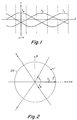
- FIGURE 1 is a conventional amplitude-time diagram of three phases of AC current or voltage, with a 120° relative temporal phase ⁇ t, which is often used to describe three-phase systems.
- the abbreviation AC stands for "alternating current,” which in many cases is a misnomer, as the term may refer to either alternating voltage or alternating current, or both.
- a voltage or current is "alternating” if the instantaneous value dwells periodically at positive values followed by a dwell at a negative value, where the terms “positive” or “negative” refer to direction in an electrical, rather than mechanical, sense.
- two orthogonal ⁇ and ⁇ components are the fundamental ordinates, and the ⁇ axis corresponds with an "a" axis.
- Two additional b and c axes lie 120° from the a axis.
- Voltage or current X a always lies along the a axis, and its instantaneous amplitude changes with time.
- X b and X c always lie along the b and c axes, respectively, and their amplitudes also change with time.
- the amplitudes of X a , X b , and X c of FIGURE 2 are such as to sum together, to correspond to a vector.
- each phase may be associated with a common-mode component, which offsets the alternating component of that phase.
- the plot of FIGURE 2 assumes or represents a situation in which there is no common-mode component. If there is a common-mode component in a balanced three-phase system, it cancels and does not appear in the alpha and beta components. Since the common-mode components cancel, a plot such as that of FIGURE 2 would not show them, even if present. However, such a common-mode component may exist, even if it is not represented in the two-dimensional plot of FIGURE 2.
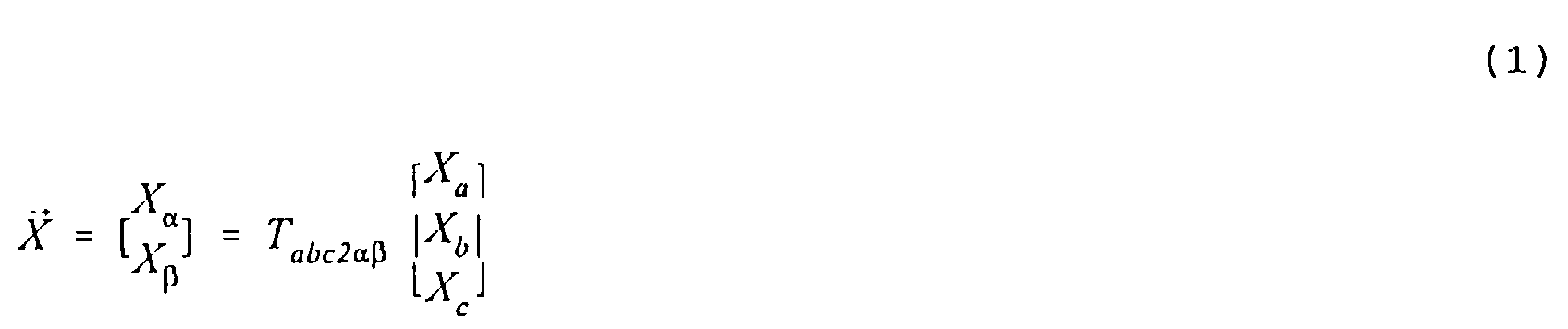
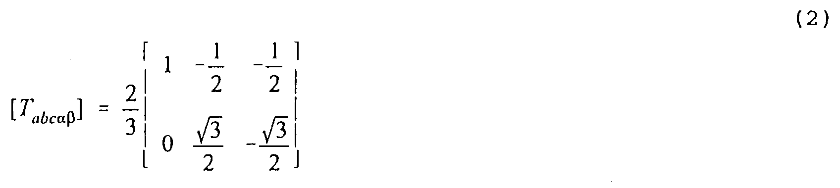
- vector X may be represented by the modified transformation set forth below in relation to equations (3) and (4) where the elements of the lowest row of the matrix, having value "1/2," represent the common-mode component.
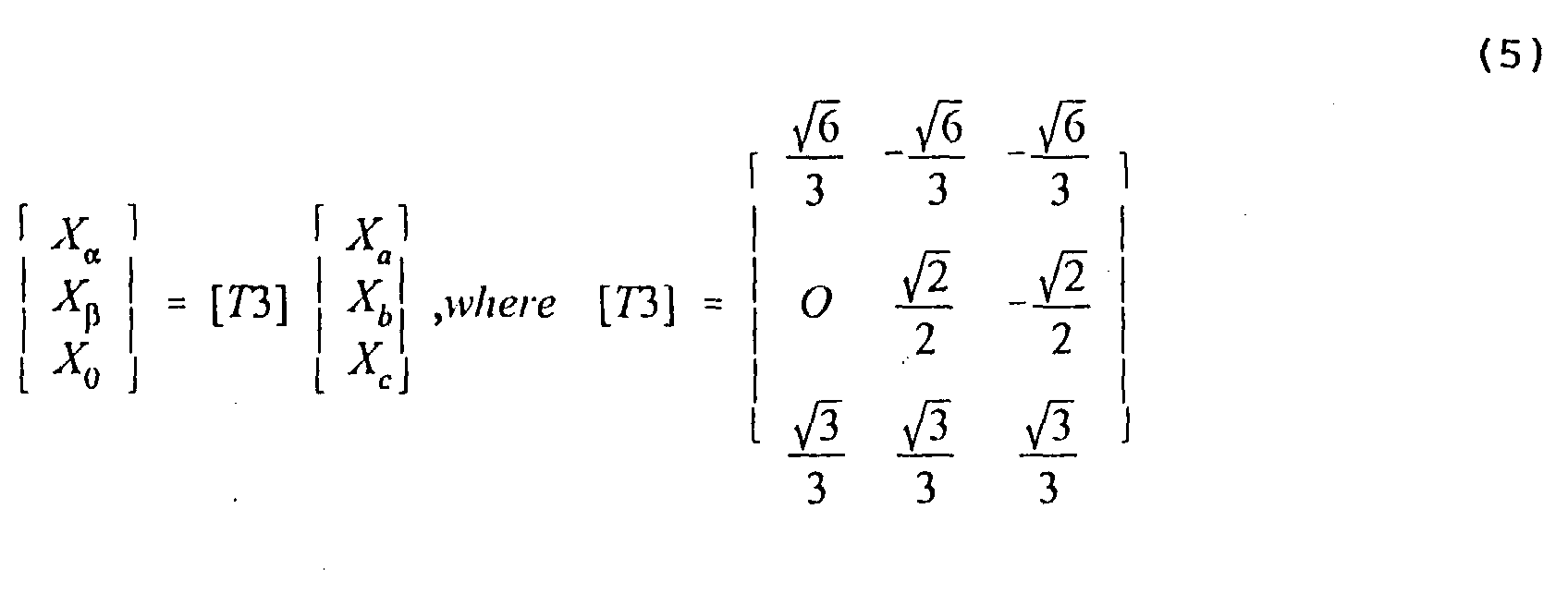
- the additional X 0 component is known as the zero sequence component.
- the common-mode component which is represented by the zero-sequence component are often represented by a vector orthogonal to the ⁇ - ⁇ plane of FIGURE 2. Application of such a vector orthogonal to the ⁇ - ⁇ plane results in a three-dimensional system of mutually orthogonal coordinates.
- An 2N+1-phase AC machine arrangement includes a plurality N of AC machines, where the AC machines may be motors or generators.
- the arrangement includes N AC machines.
- Each of the N ac machines has 2N+1 windings through which alternating current flows; naturally, there may be more windings, but the effective number of windings should be 2N+1.
- the arrangement also includes a controllable 2N+1-phase inverter, for generating 2N+1 phases of current for the N machines.
- An interconnection arrangement is coupled to the inverter and to the N AC machines, for interconnecting the N windings of the N AC machines so that the current flowing through each winding of each machine flows through windings of each of the others of the N AC machines.
- a control arrangement is coupled to the inverter, for controlling the 2N+1 phases in N mutually orthogonal sets of phases, for thereby controlling the N AC machines independently of each other.
- each of 2N+1 windings of the 2N+1-phase AC machines is electrically oriented in a particular spatial phase progression, and the interconnection arrangement interconnects the windings of the N AC machines in a manner such that the current flowing through a winding of one of the AC machines corresponding to a particular spatial phase flows through a winding of a different spatial phase of another one of the AC machines.
- the flow of one current through the winding of a particular spatial phase in one of the machines flows in a winding of the same spatial phase in another machine.
- N is two and 2N+1 is five, and each of the five windings of the two AC machines is oriented in each machine in a particular spatial phase, and the interconnection arrangement interconnects all five phases of a first one of the two AC machines to corresponding phases of the inverter, and connects one of the windings of the one of the AC machines for current flow through a corresponding winding of the other one of the AC machines.
- a method for controlling an AC machine system including N interconnected 2N+1-phase AC machines, where each of the AC machines includes corresponding spatial phase windings includes the step of generating 2N+1-phase currents representing N mutually orthogonal sets of two-dimensional subsets of currents.
- the currents are applied through the spatial phase windings of a first of the N AC machines with a particular correspondence of the phases of the currents to the spatial phase of the windings, and applied through the spatial phase windings of a second one of the N AC machines with a correspondence of the phases of the currents to the spatial phase of the windings which differs from the particular correspondence, in such a manner that each of the two-dimensional subsets of the currents independently controls one of the N AC machines.
- the step of generating 2N+1-phase currents includes the step of controlling a five-phase inverter coupled to a direct voltage bus.
- This particular mode of practicing the invention includes the additional step of coupling first and second ones of the N AC machines to first and second wheels of a vehicle.
- the step of controlling a five-phase inverter includes the step of controlling the switches of a five-phase inverter coupled to a traction (or other) battery.
- the step of generating 2N+1-phase currents includes the step of controlling a five-phase inverter coupled to a direct voltage bus, and an additional step is included in which a first one of the N AC machines is coupled to at least a first wheel of a vehicle, and a second one of the N AC machines is coupled to a source of mechanical drive energy, which may be an internal combustion engine.
- FIGURES 3a, 3b, and 3c are representations of the a, b, and c voltage or current components of FIGURE 1 along three mutually orthogonal X a , X b , and X c axes or Cartesian coordinates.
- the voltage or current components correspond to various instantaneous values along (or on) the X a , X b , and X c axes.
- FIGURES 3a, 3b, and 3c are different perspective or isometric views of the same vector arrangement.
- the center of the cube coincides with the center or the origin of the coordinate system, in order to simplify the representation.
- the coordinates of the center of the cube are 000.
- a hexagonal plane 312 passes through the origin 000, and cuts the cube into two identical halves.
- the orthogonal projections of axes X a , X b , and X c onto plane 312 are designated a', b', and c', respectively, and the three projections are spaced by 120° in the plane.
- the projections a', b', and c' of FIGURE 3 correspond with axes a, b, and c of FIGURE 2.
- the zero-sequence component may vary with time.
- the presence of a varying zero-sequence component is represented in FIGURE 3a by a component lying along the 0 axis, orthogonal to the ⁇ and ⁇ axes. If the zero-sequence component were fixed in magnitude, it would simply move or translate the plane 312 parallel with the 0 axis, which is a main diagonal of the cube.
- the plane of the trajectory tilts relative to plane 312 in response to the presence of such a zero-sequence component.
- FIGURE 3b represents the arrangement of FIGURE 3a with plane 312 seen edge-on, and FIGURE 3c represents a view along axis 0.
- Equation (5) represents the matrix transformation that converts a vector expressed in terms of a, b, and c components from FIGURES 3a, 3b, and 3c into a vector expressed in terms of ⁇ , ⁇ , and zero-sequence components. This is merely vector transformation from one coordinate system into another.
- the representation of a three-phase system in FIGURES 3a, 3b, and 3c allows one to understand that polyphase systems can be represented as a 2N+1-dimensional hypercube.
- a five-phase system can be represented in a manner which has two mutually orthogonal planes such as plane 312, in addition to a single zero-sequence axis.
- the two planes so represented for a five-phase system each occupy two dimensions of a four-dimensional sub-space. These two planes, being mutually orthogonal, intersect only at the origin of the coordinate system, and therefore do not interact.
- This concept can be generalized to any odd number of phases, such as seven, nine, etc.
- N AC machines are controlled by 2N+1 controlled phases of voltage or current.
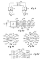
- FIGURE 4 is a simplified block diagram of two AC machines 410 and 412, each connected by means of an inverter 414, 416, respectively, to a direct-voltage bus 420 and a direct-voltage source 422 represented as a battery.
- a bus may include more than one electrical conductor.
- either AC machine may be a generator or a motor.
- both machines 410 and 412 are operated as motors, supplying mechanical energy to loads (not illustrated), with the energy being supplied from the source 422 by way of inverters 414 and 416, respectively.
- both machines may be operated as generators, with the electrical energy which they produce being rectified to direct current by the inverters 414 and 416 operated in a rectification mode.
- machine 410 may be operated as a generator, and machine 412 as a motor, for supplying energy from machine 410 to source 422 by way of inverter 414, and for supplying energy from the source 422 to machine 412 by way of inverter 416.
- the energy for motor 412 is ultimately generated by generator 410.
- the energy produced by generator 410 must pass through inverters 414 and 416 on its way to motor 412.
- FIGURE 5a illustrates an arrangement according to an aspect of the invention.
- the direct-current source (which also includes a direct-voltage source) is illustrated as a battery 422, which is connected to a direct-current bus 420, as in FIGURE 4.
- Bus 420 is connected to a five-phase inverter 514, which converts the direct voltage or current on bus 420 into five-phase voltage or current on a set 520 of conductors or current paths 520a, 520b, 520c, 520d, and 520e.
- the currents or voltages flow from set 520 of conductors or current paths, by way of a phase-swapping arrangement 550, to a five-phase AC machine 510.
- FIGURE 5b illustrates the windings associated with AC machine 510 of FIGURE 5a with its connections to the conductors or paths of set 520.
- AC machine 510 includes a set 530 of five windings 530a, 530b, 530c, 530d, and 530e.
- the individual windings 530a, 530b, 530c, 530d, and 530e of five-phase set 530 of windings is physically oriented within the machine 510 so that currents or voltages of progressive phase when applied to the windings of the set 530 results in a magnetic field which progresses around the machine.
- phase 1 (0°) is applied by way of path 520a to winding 530a
- phase 2 72° is applied by way of path 520b to winding 530b
- phase 3 144 ° is applied by way of path 520c to winding 530c
- phase 4 216° is applied by way of path 520d to winding 530d
- phase 5 (288°) is applied by way of path 520e to winding 530e
- the physical placement of the windings of set 530 is such that the fields add in-phase to form a rotating field in the machine.
- This rotating field is capable of transforming electrical energy into mechanical motion, or mechanical motion into corresponding electrical energy.
- the ends of windings 530a, 530b, 530c, 530d, and 530e remote from conductors 520a, 520b, 520c, 520d, and 520e, respectively, are connected to current paths or conductors 520a', 520b', 520c', 520d', and 520e', respectively.
- currents which flow from a conductor into a winding such as from conductor 520a into winding 530a of FIGURE 5b, also flows in the corresponding other connection of the winding, corresponding to connection or path 520a' in the case of winding 530a.
- FIGURE 5c illustrates the windings associated with AC machine 512 of FIGURE 5a, together with its connections to the conductors or paths of a set 540 of conductors or paths.
- AC machine 512 includes a set 532 of five windings 532a, 532b, 532c, 532d, and 532e.
- Machine 512 of FIGURE 5c is also associated with a set 540 of electrical conductors or paths 540a, 540b, 540c, 540d, and 540e.
- individual windings 532a, 532b, 532c, 532d, and 532e of five-phase set 532 of windings is physically oriented within the machine 512 so that currents or voltages of progressive phase when applied to the windings of the set 530 results in a magnetic field which progresses around the machine.
- phase 1 (0°) is applied by way of path 540a to winding 532a
- phase 2 72° is applied by way of path 540b to winding 532b
- phase 3 144 ° is applied by way of path 540c to winding 532c
- phase 4 216° is applied by way of path 540d to winding 532d
- phase 5 (288°) is applied by way of path 540e to winding 532e
- the physical placement of the windings of set 540 is such that the fields add in-phase to form a rotating field in AC machine 512.
- This rotating field is capable of transforming electrical energy into mechanical motion, or mechanical motion into corresponding electrical energy.
- the ends of windings 532a, 532b, 532c, 532d, and 532e remote from conductors 540a, 540b, 540c, 540d, and 540e, respectively, are connected by way of a set 540' of current paths or conductors 540a', 540b', 540c', 540d', and 540e', respectively, to a common or "short-circuiting" conductor 542.
- FIGURE 5d is a detailed view of one possible interconnection or phase swapping arrangement 550 of FIGURE 5a.
- an interconnection arrangement designated as 550 connects the conductors or current paths of set 520' with the conductors of current paths of set 540 of conductors or current paths.
- the conductors or current paths of interconnection arrangement 550 are connected in a manner which causes the certain currents to result in rotating fields in the associated machine, and to cause other of the currents to result in field cancellation.
- the fields attributable to currents ( ⁇ 1 , ⁇ 1 ) associated with one of the two orthogonal plane described in conjunction with FIGURES 3a, 3b, and 3c add to produce a rotating field, while those currents ( ⁇ 2 , ⁇ 2 ) associated with the other one of the two orthogonal planes result in fields which cancel, and which therefore result in no rotational field.
- conductor 520a' which carries currents or voltages of a phase arbitrarily designated as 0°, is connected by an interconnection path 550a to a corresponding conductor 540a of conductor set 540.
- a conductor 550b of interconnection set 550 interconnects 72° conductor 520b' of set 520' with conductor 540d of set 540.
- a conductor 550c of set 550 of conductors interconnects 144° conductor 520c' of set 520' with conductor 540b of set 540, a conductor 550d of conductor set 550 connects 216° conductor 520d' of conductor set 520' to conductor 540e of conductor set 540, and a conductor 550e of conductor set 550 connects 288° conductor 520e' of conductor set 520' to conductor 540c of conductor set 540.
- the independent operation of the two machines 510 and 512 of FIGURES 5a, 5b, 5c, and 5d can be thought of as arising out of operation of each of the two machines in a three-phase manner, which for each machine requires currents or voltages which sum to produce the rotating fields.
- These voltages or currents for each machine can be viewed as being the ⁇ and ⁇ components described in conjunction with FIGURES 2, 3a, 3b, and 3c, lying in a plane, but in which the two planes ( ⁇ 1 , ⁇ 1 ) and ( ⁇ 2 , ⁇ 2 ) are orthogonal, as described above.
- the total five-phase voltage or current may be viewed as being the vector sum of the voltage or currents associated with the two orthogonal planes.
- the orthogonality of the two planes has the physical result that the components of the five-phase voltages or currents associated with a first plane sum or add together to form a rotating field; while the voltages or currents associated with the second of the two orthogonal planes cancel.
- the addition or cancellation is dependent upon how the phases add within each machine.
- FIGURES 5a and 5d results, in AC machine 510, in addition of the fields associated with one plane ( ⁇ 1 , ⁇ 1 ), and cancellation of fields associated with the second plane ( ⁇ 2 , ⁇ 2 ), while in machine 512, the phases are rearranged in a fashion which results in addition or summation to produce rotating fields from the second plane ( ⁇ 2 , ⁇ 2 ), and cancellation of fields associated with the first plane ( ⁇ 1 , ⁇ 1 ).
- FIGURE 6 is a simplified representation of a five-phase inverter which may be used in the arrangement of FIGURE 5a.
- the direct voltage or direct current bus 420 including current paths 420a and 420b, is connected across source 422.
- Five controlled current paths 610a, 610b, 610c, 610d, and 610e extend from conductor 420a to 420b.
- Each path 610a, 610b, 610c, 610d, and 610e includes two controllable switches, which are illustrated by Xs.
- Current path 610a includes an upper switch 612a 1 and a lower switch 612a 2 , with a tap 614a therebetween.
- Current path 610b includes an upper switch 612b 1 and a lower switch 612b 2 with a tap 614b therebetween
- current path 610c includes an upper switch 612c 1 and a lower switch 612c 2 with a tap 614c therebetween
- current path 610d includes an upper switch 612d 1 and a lower switch 612d 2 with a tap 614d therebetween
- current path 610e includes an upper switch 612e 1 and a lower switch 612e 2 and a tap 614e therebetween.
- the AC conductors 520a, 520b, 520c, 520d, and 520e of set 520 of conductors are connected to taps 614a, 614b, 614c, 614d, and 614e, respectively.
- Inverter 514 of FIGURE 6 also includes a switch controller illustrated as a block 608 which controls the switches in a manner appropriate for generation of five-phase currents or voltages. Controllers for switched inverters are well known in the art, and a controller for five-phase operation should be well within the knowledge of a person of average skill in the art.
- FIGURE 7 is a simplified block diagram of a prior-art three-phase AC machine controller of the Field-Oriented Control (FOC) type.
- the AC machine is an induction machine (motor or generator) 710 driven by a, b, and c phases having relative 0°, 120°, and 240° phases.
- a common current path or short-circuiting bus is illustrated as 712.
- Current samplers illustrated as 714a and 714b sample the currents in the a and b conductive paths, and couple signal samples to a T3 block 716.
- Controller 720 produces d ⁇ and d ⁇ duty, cycle control signals, which are applied to an inverse transformation T3 -1 illustrated as a block 722, which converts the d ⁇ and d ⁇ duty cycle control signals into d a , d b , and d c control signals.
- the d a , d b , and d c control signals are applied to a three-phase inverter 724, which controls the power flow to and from a bus 420 and an associated source illustrated as a battery 422.
- a three-phase inverter 724 which controls the power flow to and from a bus 420 and an associated source illustrated as a battery 422.
- the source 422 is a traction battery
- the motor 710 drives at least one wheel of the vehicle
- the FOC controller 720 receives other control signals indicative of the amount of power which is to be coupled to the motor, the amount of regenerative braking to be employed, and various other signals.
- another AC machine in the form of an electric generator driven by a fuel-operated machine may be connected to the three-phase inverter, as described in greater detail in U.S. Patent 5,828,201, issued 10/27/98 in the name of Hoffman et al.; and 5,869,950, issued February 9, 1999 in the name of Hoffman et al.
- an FOC controlled arrangement uses five-phase control of a pair of AC machines.
- FIGURE 8 illustrates an arrangement according to this aspect of the invention.
- a controlled five-phase inverter 824 produces five-phase voltage or current on a set 821 of conductors, for application to two five-phase motors, connected as in FIGURE 5a, illustrated together as a block 810.
- block 816 of FIGURE 8 transforms or converts i a , i b , i c , i d and i e into i ⁇ 1 , i ⁇ 1 and i ⁇ 2 , i ⁇ 2 components, and a 0 component.
- the i ⁇ 1 and i ⁇ 1 components are applied, together with ⁇ 1 sensor information relating to the angular position of the rotor associated with the first motor, to a block 820 1 , designated "AC motor vector control," which is the FOC controller for the first motor of the two five-phase motors of block 810.
- the output of FOC controller 820 1 includes control signals V ⁇ 1 and V ⁇ 1 , which are applied to a T5 -1 transformation block 822.
- the i ⁇ 2 and i ⁇ 2 components produced by block 816 are applied, together with ⁇ 2 sensor information relating to the angular position of the rotor associated with the second motor, to a block 820 2 , designated "AC motor vector control,” which is the FOC controller for the second motor of the two five-phase motors of block 810.
- the output of FOC controller 820 2 includes control signals V ⁇ 2 and V ⁇ 2 , which are applied to T5 -1 transformation block 822, together with the V ⁇ 1 and V ⁇ 1 commands from FOC controller 820 1 and the zero-sequence current signal from block 816.
- Block 822 performs a T5 -1 transformation to convert the V ⁇ 1 , V ⁇ 1 , 0, V ⁇ 2 and V ⁇ 2 signals into five-phase inverter control signals V a , V b , V c , V d , and V e signals.
- the V a , V b , V c , V d , and V e signals produced by block 822 are applied to five-phase inverter block 824 for control of the set 612 of switches of FIGURE 6.
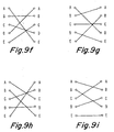
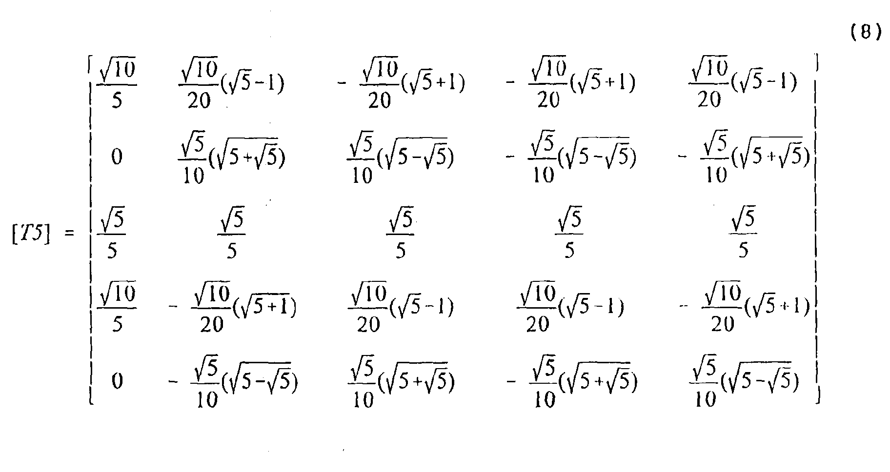
- the T5 block 816 of FIGURE 8 represents a transformation between (a, b, c, d, e) coordinates and ( ⁇ 1, ⁇ 1, 0, ⁇ 2, ⁇ 2) coordinates. More particularly, the transformation is set forth in equation (7) where one possible solution of matrix [T5] is set forth in equation (8). Similarly, the matrix [T5 -1 ] of block 822 of FIGURE 8 is defined by equation (9) where matrix [T5 -1 ] is set forth in equation (10). There are at least ten solutions, one of which is manifested in the phase swapping arrangement of FIGURE 5d. The other nine solutions produce different shifts, which are illustrated in FIGURES 9a, 9b, 9c, 9d, 9e, 9f, 9g, 9h, and 9i, and require no further explanation.
- FIGURE 10 illustrates a general N-machine system using 2N+1 phases.
- Battery 422 is coupled by bus 420 to a (2N+1)-phase inverter, which produces (2N+1)-phase drive according to the invention on (2N+1) conductors of a set 1020a of conductors.
- Set 1020a connects to a set of (2N+1) connections of a (2N+1)-winding machine 1010a.
- the other ends of the (2N+1) windings of machine 1010a are connected by way of a set 1020a' of conductors to the a first phase swapping block 1050a.
- the phase-swapping block is connected by way of a set 1020b to the terminals of a second machine 1010b, also having (2N+1) windings.
- the other ends of the windings of machine 1010b are connected by way of a set 1020b' to a second phase swapping block 1050b.
- the output of phase swapping block 1050b is connected by way of a further set 1020c of conductors, . . ., and so forth, until the last set of conductors is connected to terminals of the N th machine 1010N.
- the (2N+1) terminals of machine 1010N which are remote from the other machines are connected to a common conductor 1042.
- controllers of the various embodiments may include analog or digital circuits, or both.
- the terms "between” and “across” when used in the context of an electrical system have meanings which are not the same as their meanings in mechanics or space. While the descriptions of the controllers have not adverted to use of the AC machines as both generators and motors, depending upon the drive and load conditions to which the machines are subject, they may operate in either mode, depending upon those conditions, and the "inverter" portion of the system may in the case of operation as a generator perform a function equivalent to rectification, to extract AC energy from the generator, and to couple that energy to the direct voltage or current bus.
- a 2N+1-phase (five-phase) AC machine (410, 412, 510, 512, 710, 810) arrangement includes a plurality N of AC machines (410, 412, 510, 512, 710, 810), where the AC machines (410, 412, 510, 512, 710, 810) may be motors or generators.
- the arrangement includes N AC machines (410, 412, 510, 512, 710, 810).
- Each of the N ac machines (410, 412, 510, 512, 710, 810) has 2N+1 windings (530, 532) through which alternating current flows; naturally, there may be more windings (530, 532), but the effective number of windings (530, 532) should be 2N+1.
- the arrangement also includes a controllable 2N+1-phase inverter (414, 416, 514, 724, 824), for generating 2N+1 phases of current for the N machines (410, 412, 510, 512, 710, 810).
- An interconnection arrangement (550) is coupled to the inverter (414, 416, 514, 724, 824) and to the N AC machines (410, 412, 510, 512, 710, 810), for interconnecting the N windings (530, 532) of the N AC machines (410, 412, 510, 512, 710, 810) so that the current flowing through each winding of each machine (410, 412, 510, 512, 710, 810) flows through windings (530, 532) of each of the others of the N AC machines (410, 412, 510, 512, 710, 810).
- a control arrangement (608, 716, 720, 722, 816, 820 1 , 820 2 , 822) is coupled to the inverter (414, 416, 514, 724, 824), for controlling the 2N+1 phases in N mutually orthogonal sets of phases, for thereby controlling the N AC machines (410, 412, 510, 512, 710, 810) independently of each other.
- each of 2N+1 windings (530, 532) of the 2N+1-phase AC machines (510, 512, 810) is electrically oriented in a particular spatial phase progression, and the interconnection arrangement (550) interconnects the windings (530, 532) of the N AC machines (510, 810) in a manner such that the current flowing through a winding (530b) of one of the AC machines (510, 512, 810) corresponding to a particular spatial phase (b) flows through a winding (532d) of a different spatial phase (d) of another one of the AC machines (512, 810).
- the flow of one current through the winding (530a) of a particular spatial phase (a) in one of the machines (510, 810) flows in a winding (532a) of the same spatial phase (a) in another machine (512, 810).
- N is two and 2N+1 is five, and each of the five windings (the windings of sets 530 and 532) of the two AC machines (510, 512, 810) is oriented in each machine (510, 512, 810) in a particular spatial phase, and the interconnection arrangement (550) interconnects all five phases of a first one of the two AC machines (510) to corresponding phases of the inverter (514, 824), and connects one of the windings (530a) of the one of the AC machines (510) for current flow through a corresponding winding (532a) of the other one of the AC machines (512).
- a method for controlling an AC machine system including N interconnected 2N+1-phase AC machines, where each of the AC machines includes corresponding spatial phase windings includes the step of generating 2N+1-phase currents representing N mutually orthogonal sets of two-dimensional subsets of currents.
- the currents are applied through the spatial phase windings of a first of the N AC machines with a particular correspondence of the phases of the currents to the spatial phase of the windings, and applied through the spatial phase windings of a second one of the N AC machines with a correspondence of the phases of the currents to the spatial phase of the windings which differs from the particular correspondence, in such a manner that each of the two-dimensional subsets of the currents independently controls one of the N AC machines.
- the step of generating 2N+1-phase currents includes the step of controlling a five-phase inverter coupled to a direct voltage bus.
- This particular mode of practicing the invention includes the additional step of coupling first and second ones of the N AC machines to first and second wheels of a vehicle.
- the step of controlling a five-phase inverter includes the step of controlling the switches of a five-phase inverter coupled to a traction battery.
- the step of generating 2N+1-phase currents includes the step of controlling a five-phase inverter coupled to a direct voltage bus, and an additional step is included in which a first one of the N AC machines is coupled to at least a first wheel of a vehicle, and a second one of the N AC machines is coupled to a source of mechanical drive energy, which may be an internal combustion engine.
Landscapes
- Engineering & Computer Science (AREA)
- Power Engineering (AREA)
- Transportation (AREA)
- Mechanical Engineering (AREA)
- Life Sciences & Earth Sciences (AREA)
- Sustainable Development (AREA)
- Sustainable Energy (AREA)
- Control Of Ac Motors In General (AREA)
- Control Of Multiple Motors (AREA)
- Electric Propulsion And Braking For Vehicles (AREA)
Abstract
Description





Claims (8)
- An 2N+1-phase AC machine induction motor/generator arrangement, comprising:N AC machines, each of said N ac machines having 2N+1 windings through which alternating current flows;a controllable 2N+1-phase inverter for generating 2N+1 phases of current for driving said N machines;interconnection means coupled to said inverter and to said N AC machines, for interconnecting said N windings of said N AC machines so that the current flowing through each winding of each machine flows through windings of each of the others of said N AC machines; andcontrol means coupled to said inverter, for controlling said 2N+1 phases in N mutually orthogonal sets of phases, for thereby controlling said N AC machines independently of each other.
- An arrangement according to claim 1, wherein each of 2N+1 windings of said 2N+1-phase AC machines is electrically oriented in a particular spatial phase progression; andsaid interconnection means interconnects said windings of said N AC machines in a manner such that the current flowing through a winding of one of said AC machines corresponding to a particular spatial phase flows through a winding of a different spatial phase of another one of said AC machines.
- An arrangement according to claim 1, wherein N is two and 2N+1 is five, and each of the five windings of said two AC machines is oriented in each machine in a particular spatial phase; andsaid interconnection means interconnects all five phases of a first one of said two AC machines to corresponding phases of said inverter, and connects one of said windings of said one of said AC machines for current flow through a corresponding winding of the other one of said AC machines.
- A method for controlling an AC machine system including N interconnected 2N+1-phase AC machines, each of which AC machines includes corresponding spatial phase windings, said method comprising the steps of:generating 2N+1-phase currents representing N mutually orthogonal sets of two-dimensional subsets of currents;applying said currents of said 2n+1 phases through said spatial phase windings of a first of said N AC machines with a particular correspondence of said phases of said currents to said spatial phase of said windings; andapplying said currents of said 2N+1 phases through said spatial phase windings of a second one of said N AC machines with a correspondence of said phases of said currents to said spatial phase of said windings which differs from said particular correspondence, in such a manner that each of said two-dimensional subsets of said currents independently controls one of said N AC machines.
- A method according to claim 4, wherein:said step of generating 2N+1-phase currents includes the step of controlling a five-phase inverter coupled to a direct voltage bus;and comprising the additional step of coupling first and second ones of said N AC machines to first and second wheels of a vehicle.
- A method according to claim 5, wherein said step of controlling a five-phase inverter includes the step of controlling the switches of a five-phase inverter coupled to a traction battery.
- A method according to claim 4, wherein:said step of generating 2N+1-phase currents includes the step of controlling a five-phase inverter coupled to a direct voltage bus;and comprising the additional step of coupling a first one of said N AC machines to at least a first wheel of a vehicle, and coupling a second one of said N AC machines to a source of mechanical drive energy.
- A method according to claim 7, wherein said step of coupling a second one of said N AC machines to a source of mechanical drive energy includes the step of coupling said second one of said N AC machines to an internal combustion engine.
Applications Claiming Priority (2)
| Application Number | Priority Date | Filing Date | Title |
|---|---|---|---|
| US266645 | 1999-03-11 | ||
| US09/266,645 US6072287A (en) | 1999-03-11 | 1999-03-11 | Polyphase AC machine controller |
Publications (3)
| Publication Number | Publication Date |
|---|---|
| EP1037376A2 true EP1037376A2 (en) | 2000-09-20 |
| EP1037376A3 EP1037376A3 (en) | 2002-11-27 |
| EP1037376B1 EP1037376B1 (en) | 2006-08-02 |
Family
ID=23015408
Family Applications (1)
| Application Number | Title | Priority Date | Filing Date |
|---|---|---|---|
| EP00103264A Expired - Lifetime EP1037376B1 (en) | 1999-03-11 | 2000-02-17 | Polyphase AC machine controller |
Country Status (8)
| Country | Link |
|---|---|
| US (1) | US6072287A (en) |
| EP (1) | EP1037376B1 (en) |
| JP (1) | JP4663841B2 (en) |
| KR (1) | KR100674650B1 (en) |
| CN (1) | CN1214515C (en) |
| CA (1) | CA2298751C (en) |
| DE (1) | DE60029664T2 (en) |
| TW (1) | TW477102B (en) |
Families Citing this family (11)
| Publication number | Priority date | Publication date | Assignee | Title |
|---|---|---|---|---|
| US6362535B1 (en) | 1999-08-11 | 2002-03-26 | Bae Systems | Method and apparatus for after-treatment of hev exhaust |
| US6538400B2 (en) * | 2001-05-08 | 2003-03-25 | Meritor Light Vehicle Technology, Llc | Control system for an electric motor |
| EP1516409B1 (en) * | 2002-04-03 | 2007-12-12 | Borealis Technical Limited | High phase order elctrical rotating machine with distributed windings |
| US6791226B1 (en) * | 2003-09-10 | 2004-09-14 | Wavecrest Laboratories, Llc | Multiphase motor winding topology and control |
| CN100417539C (en) * | 2004-07-05 | 2008-09-10 | 段志辉 | Electro-mechanic mixed driving system of automobile |
| JP4752352B2 (en) * | 2005-06-24 | 2011-08-17 | トヨタ自動車株式会社 | AC voltage output device and hybrid vehicle equipped with the same |
| US7591748B2 (en) * | 2006-08-29 | 2009-09-22 | Gm Global Technology Operations, Inc. | Electrically variable transmission with a compound motor/generator |
| US8193747B2 (en) * | 2009-05-28 | 2012-06-05 | GM Global Technology Operations LLC | Methods, systems and apparatus for controlling operation of two alternating current (AC) machines |
| DE102012217116A1 (en) * | 2012-09-24 | 2014-03-27 | Robert Bosch Gmbh | Method for determining the phase currents of an electrical machine with a power converter |
| WO2019068330A1 (en) * | 2017-10-05 | 2019-04-11 | Thyssenkrupp Presta Ag | Drivetrain with electronic differential for a motor vehicle having multiphase electric motors driven by a single inverter |
| JP6854849B2 (en) * | 2019-06-19 | 2021-04-07 | 三菱電機株式会社 | Manufacturing method of current detector and current detector |
Family Cites Families (8)
| Publication number | Priority date | Publication date | Assignee | Title |
|---|---|---|---|---|
| JPS5192019A (en) * | 1975-02-08 | 1976-08-12 | ||
| JPS53153611U (en) * | 1977-05-11 | 1978-12-02 | ||
| US4298831A (en) * | 1980-03-24 | 1981-11-03 | General Electric Company | Method and apparatus for operating a plurality of parallel coupled, arbitrarily loaded induction machines from a single controlled current inverter |
| JPS6310798U (en) * | 1986-07-04 | 1988-01-23 | ||
| JPH01308196A (en) * | 1988-06-02 | 1989-12-12 | Fuji Electric Co Ltd | Inverter-driven motor |
| JPH04248392A (en) * | 1991-01-24 | 1992-09-03 | Fuji Electric Co Ltd | Synchronous operation of ac servomotor with synchronous motor |
| JPH07147704A (en) * | 1993-11-25 | 1995-06-06 | Nippondenso Co Ltd | Driving gear for electric vehicle |
| US5903115A (en) * | 1997-11-24 | 1999-05-11 | Alliedsignal Inc. | Auxiliary system including a plurality of ac motors powered directly by an electric generator |
-
1999
- 1999-03-11 US US09/266,645 patent/US6072287A/en not_active Expired - Lifetime
-
2000
- 2000-02-10 CA CA2298751A patent/CA2298751C/en not_active Expired - Lifetime
- 2000-02-17 DE DE60029664T patent/DE60029664T2/en not_active Expired - Lifetime
- 2000-02-17 EP EP00103264A patent/EP1037376B1/en not_active Expired - Lifetime
- 2000-03-07 KR KR1020000011287A patent/KR100674650B1/en not_active Expired - Fee Related
- 2000-03-08 JP JP2000063907A patent/JP4663841B2/en not_active Expired - Fee Related
- 2000-03-13 CN CNB001040359A patent/CN1214515C/en not_active Expired - Fee Related
- 2000-04-20 TW TW089104393A patent/TW477102B/en not_active IP Right Cessation
Also Published As
| Publication number | Publication date |
|---|---|
| CN1214515C (en) | 2005-08-10 |
| JP2000295899A (en) | 2000-10-20 |
| KR20010006746A (en) | 2001-01-26 |
| EP1037376A3 (en) | 2002-11-27 |
| KR100674650B1 (en) | 2007-01-25 |
| DE60029664T2 (en) | 2007-10-18 |
| TW477102B (en) | 2002-02-21 |
| CA2298751C (en) | 2010-11-23 |
| CN1267129A (en) | 2000-09-20 |
| JP4663841B2 (en) | 2011-04-06 |
| DE60029664D1 (en) | 2006-09-14 |
| US6072287A (en) | 2000-06-06 |
| EP1037376B1 (en) | 2006-08-02 |
| CA2298751A1 (en) | 2000-09-11 |
Similar Documents
| Publication | Publication Date | Title |
|---|---|---|
| JP3555567B2 (en) | Control device for rotating electric machine | |
| US8269434B2 (en) | Electrical system using phase-shifted carrier signals and related operating methods | |
| US8547041B2 (en) | Power conversion device | |
| US6072287A (en) | Polyphase AC machine controller | |
| CN102113204B (en) | Synchronous electric motor driving system | |
| US5705909A (en) | Control for AC motor having parallel sets of three-phase windings with only one current sensor per set | |
| CN102195550B (en) | Methods, systems and apparatus for optimization of third harmonic current injection in a multi-phase machine | |
| EP0493848B1 (en) | Electric motor drive and power processing apparatus | |
| US8604739B2 (en) | Vector control for an axial gap motor | |
| EP1107434B1 (en) | Motor/generator | |
| CN102308470A (en) | Power conversion device | |
| EP1087518B1 (en) | Control device and method for motor/generator having a plurality of independently rotating rotors and one stator | |
| US7023171B2 (en) | Integrated inverter for driving multiple electric machines | |
| JP7415742B2 (en) | power converter | |
| EP1172926A2 (en) | Power output device | |
| CN111200388A (en) | Partial load phase deactivation for multi-phase electric machines | |
| Kim et al. | Modified direct torque control system of five phase induction motor | |
| JP4134509B2 (en) | Charging device and electric vehicle | |
| MXPA00002503A (en) | Polyphase ac machine controller | |
| Elbachir et al. | Artificial neural networks direct torque control of single inverter feed two induction motors | |
| US12447833B2 (en) | Multilevel inverter current sensing | |
| JP2004187450A (en) | Power conversion device using electric motor | |
| JP7598970B2 (en) | Method for operating an electric drive system having multiple energy storage means - Patents.com | |
| JP4696703B2 (en) | Inverter device | |
| Li et al. | Two-Phased SVPWM based on H-bridged Structure |
Legal Events
| Date | Code | Title | Description |
|---|---|---|---|
| PUAI | Public reference made under article 153(3) epc to a published international application that has entered the european phase |
Free format text: ORIGINAL CODE: 0009012 |
|
| AK | Designated contracting states |
Kind code of ref document: A2 Designated state(s): AT BE CH CY DE DK ES FI FR GB GR IE IT LI LU MC NL PT SE |
|
| AX | Request for extension of the european patent |
Free format text: AL;LT;LV;MK;RO;SI |
|
| RAP1 | Party data changed (applicant data changed or rights of an application transferred) |
Owner name: BAE SYSTEMS CONTROLS, INC. |
|
| PUAL | Search report despatched |
Free format text: ORIGINAL CODE: 0009013 |
|
| AK | Designated contracting states |
Kind code of ref document: A3 Designated state(s): AT BE CH CY DE DK ES FI FR GB GR IE IT LI LU MC NL PT SE |
|
| AX | Request for extension of the european patent |
Free format text: AL;LT;LV;MK;RO;SI |
|
| RIC1 | Information provided on ipc code assigned before grant |
Free format text: 7H 02P 7/74 A, 7H 02P 21/00 B |
|
| 17P | Request for examination filed |
Effective date: 20030226 |
|
| AKX | Designation fees paid |
Designated state(s): DE FR GB IT NL SE |
|
| 17Q | First examination report despatched |
Effective date: 20050428 |
|
| GRAP | Despatch of communication of intention to grant a patent |
Free format text: ORIGINAL CODE: EPIDOSNIGR1 |
|
| RIC1 | Information provided on ipc code assigned before grant |
Ipc: H02P 5/74 20060101AFI20060112BHEP Ipc: H02P 21/00 20060101ALI20060112BHEP |
|
| GRAS | Grant fee paid |
Free format text: ORIGINAL CODE: EPIDOSNIGR3 |
|
| GRAA | (expected) grant |
Free format text: ORIGINAL CODE: 0009210 |
|
| AK | Designated contracting states |
Kind code of ref document: B1 Designated state(s): DE FR GB IT NL SE |
|
| PG25 | Lapsed in a contracting state [announced via postgrant information from national office to epo] |
Ref country code: IT Free format text: LAPSE BECAUSE OF FAILURE TO SUBMIT A TRANSLATION OF THE DESCRIPTION OR TO PAY THE FEE WITHIN THE PRESCRIBED TIME-LIMIT;WARNING: LAPSES OF ITALIAN PATENTS WITH EFFECTIVE DATE BEFORE 2007 MAY HAVE OCCURRED AT ANY TIME BEFORE 2007. THE CORRECT EFFECTIVE DATE MAY BE DIFFERENT FROM THE ONE RECORDED. Effective date: 20060802 |
|
| REG | Reference to a national code |
Ref country code: GB Ref legal event code: FG4D |
|
| REF | Corresponds to: |
Ref document number: 60029664 Country of ref document: DE Date of ref document: 20060914 Kind code of ref document: P |
|
| REG | Reference to a national code |
Ref country code: SE Ref legal event code: TRGR |
|
| ET | Fr: translation filed | ||
| PLBE | No opposition filed within time limit |
Free format text: ORIGINAL CODE: 0009261 |
|
| STAA | Information on the status of an ep patent application or granted ep patent |
Free format text: STATUS: NO OPPOSITION FILED WITHIN TIME LIMIT |
|
| 26N | No opposition filed |
Effective date: 20070503 |
|
| PGFP | Annual fee paid to national office [announced via postgrant information from national office to epo] |
Ref country code: SE Payment date: 20150226 Year of fee payment: 16 |
|
| REG | Reference to a national code |
Ref country code: FR Ref legal event code: PLFP Year of fee payment: 17 |
|
| REG | Reference to a national code |
Ref country code: SE Ref legal event code: EUG |
|
| PG25 | Lapsed in a contracting state [announced via postgrant information from national office to epo] |
Ref country code: SE Free format text: LAPSE BECAUSE OF NON-PAYMENT OF DUE FEES Effective date: 20160218 |
|
| REG | Reference to a national code |
Ref country code: FR Ref legal event code: PLFP Year of fee payment: 18 |
|
| PGFP | Annual fee paid to national office [announced via postgrant information from national office to epo] |
Ref country code: FR Payment date: 20170223 Year of fee payment: 18 Ref country code: DE Payment date: 20170227 Year of fee payment: 18 |
|
| PGFP | Annual fee paid to national office [announced via postgrant information from national office to epo] |
Ref country code: NL Payment date: 20170226 Year of fee payment: 18 Ref country code: GB Payment date: 20170227 Year of fee payment: 18 |
|
| PGFP | Annual fee paid to national office [announced via postgrant information from national office to epo] |
Ref country code: IT Payment date: 20170223 Year of fee payment: 18 |
|
| REG | Reference to a national code |
Ref country code: DE Ref legal event code: R119 Ref document number: 60029664 Country of ref document: DE |
|
| REG | Reference to a national code |
Ref country code: NL Ref legal event code: MM Effective date: 20180301 |
|
| GBPC | Gb: european patent ceased through non-payment of renewal fee |
Effective date: 20180217 |
|
| REG | Reference to a national code |
Ref country code: FR Ref legal event code: ST Effective date: 20181031 |
|
| PG25 | Lapsed in a contracting state [announced via postgrant information from national office to epo] |
Ref country code: NL Free format text: LAPSE BECAUSE OF NON-PAYMENT OF DUE FEES Effective date: 20180301 |
|
| PG25 | Lapsed in a contracting state [announced via postgrant information from national office to epo] |
Ref country code: DE Free format text: LAPSE BECAUSE OF NON-PAYMENT OF DUE FEES Effective date: 20180901 |
|
| PG25 | Lapsed in a contracting state [announced via postgrant information from national office to epo] |
Ref country code: IT Free format text: LAPSE BECAUSE OF NON-PAYMENT OF DUE FEES Effective date: 20180217 Ref country code: GB Free format text: LAPSE BECAUSE OF NON-PAYMENT OF DUE FEES Effective date: 20180217 Ref country code: FR Free format text: LAPSE BECAUSE OF NON-PAYMENT OF DUE FEES Effective date: 20180228 |