EP1037329A2 - Electrical switching connector - Google Patents
Electrical switching connector Download PDFInfo
- Publication number
- EP1037329A2 EP1037329A2 EP00104769A EP00104769A EP1037329A2 EP 1037329 A2 EP1037329 A2 EP 1037329A2 EP 00104769 A EP00104769 A EP 00104769A EP 00104769 A EP00104769 A EP 00104769A EP 1037329 A2 EP1037329 A2 EP 1037329A2
- Authority
- EP
- European Patent Office
- Prior art keywords
- contact portion
- switch terminal
- ground terminals
- pair
- electrical switching
- Prior art date
- Legal status (The legal status is an assumption and is not a legal conclusion. Google has not performed a legal analysis and makes no representation as to the accuracy of the status listed.)
- Withdrawn
Links
- 230000000295 complement effect Effects 0.000 claims abstract description 8
- 230000013011 mating Effects 0.000 claims abstract description 8
- 239000007769 metal material Substances 0.000 claims description 7
- 239000003990 capacitor Substances 0.000 claims description 3
- 239000003989 dielectric material Substances 0.000 description 1
- 239000002991 molded plastic Substances 0.000 description 1
- 238000000465 moulding Methods 0.000 description 1
- 239000004033 plastic Substances 0.000 description 1
- 238000005476 soldering Methods 0.000 description 1
- 230000007704 transition Effects 0.000 description 1
Images


Classifications
-
- H—ELECTRICITY
- H01—ELECTRIC ELEMENTS
- H01R—ELECTRICALLY-CONDUCTIVE CONNECTIONS; STRUCTURAL ASSOCIATIONS OF A PLURALITY OF MUTUALLY-INSULATED ELECTRICAL CONNECTING ELEMENTS; COUPLING DEVICES; CURRENT COLLECTORS
- H01R13/00—Details of coupling devices of the kinds covered by groups H01R12/70 or H01R24/00 - H01R33/00
- H01R13/66—Structural association with built-in electrical component
- H01R13/70—Structural association with built-in electrical component with built-in switch
- H01R13/703—Structural association with built-in electrical component with built-in switch operated by engagement or disengagement of coupling parts, e.g. dual-continuity coupling part
- H01R13/7031—Shorting, shunting or bussing of different terminals interrupted or effected on engagement of coupling part, e.g. for ESD protection, line continuity
Definitions
- This invention generally relates to the art of electrical connectors and, particularly, to an electrical switching connector, such as a radio frequency transceiver connector which might be mounted on a printed circuit board.
- Radio frequency electrical connectors are used in a wide variety of applications. Such connectors are used in mobile telephones, global positioning systems and the like. Basically, such a connector is a microwave connector.
- Such connectors is an electrical switching connector used in a transceiver of such devices which requires an antenna, such as a mobile telephone.
- the transceiver may be normally connected to an internal antenna, and switching terminals are provided for connecting the unit to an external antenna.
- the switching terminals are normally closed, and a terminal from a coaxial cable opens the normally closed terminals to disconnect the transceiver from the internal antenna and connect the transceiver to the external antenna.
- ground terminals also are employed in conjunction with the switching terminals.
- the present invention is directed to providing such a connector in the form of a radio frequency receptacle which is extremely simple and, consequently, quite inexpensive.
- An object, therefore, of the invention is to provide a new and improved electrical switching connector of the character described.
- Another object of the invention is to provide a radio frequency switching connector for mounting on a printed circuit board.
- the connector includes a molded dielectric housing defining a receptacle.
- a first switch terminal is at least partially overmolded by the housing and includes a tail portion projecting from the housing for connection to a printed circuit board and a contact portion at the receptacle.
- a second switch terminal is mounted in the housing and includes a tail portion projecting from the housing for connection to the printed circuit board and a flexible contact portion projecting into the receptacle and engageable with the contact portion of the first switch terminal. Therefore, a terminal of a complementary mating connector can be inserted into the receptacle and in engagement with the flexible contact portion of the second switch terminal to move the flexible contact portion out of engagement with the contact portion of the first switch terminal.
- a pair of ground terminals are at least partially overmolded by the housing and include tail portions projecting from the housing for connection to the printed circuit board. Each ground terminal is juxtaposed alongside one of the switch terminals.
- all of the terminals are stamped and formed of sheet metal material. All of the tail portions of the terminals are generally coplanar for connection to a surface of the printed circuit board. The contact portion of the first switch terminal and body portions of the pair of ground terminals also are coplanar in a plane offset from the plane of the tail portions of the terminals. At least a portion of the second switch terminal overlaps at least a portion of one of the ground terminals to define a capacitor therebetween.
- ground terminals are shown herein as being integrally joined.
- the pair of ground terminals form the legs of a generally U-shaped configuration, with ends of the legs being integrally joined by a cross portion of the U-shaped configuration which surrounds three sides of the contact portion of the first switch terminal.
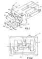
- an electrical switching connector generally designated 12, which includes a one-piece housing, generally designated 14.
- the housing is unitarily molded of dielectric material such as plastic or the like.
- the housing has a bottom mounting surface 16 for mounting the connector on the surface of a printed circuit board (not shown).
- the housing has a rear terminating end 18 (Fig. 1) and a front receptacle end 20 defining a receptacle 22 (Fig. 2) which receives at least a terminal blade of a complementary mating connector, such as for a coaxial cable coupled to an external antenna.
- switching connector 12 includes a first switch terminal, generally designated 24; a second switch terminal, generally designated 26; a first ground terminal, generally designated 28; and a second ground terminal, generally designated 30. All of the terminals are stamped and formed of conductive sheet metal material. All of the terminals 24-30 have coplanar tail portions 24a-30a, respectively, for connection to appropriate power and ground circuit traces on the printed circuit board, as by soldering.
- First switch terminal 24 is the "switched" terminal of the connector and includes an elongated body portion 24b extending through housing 14 and including a widened distal end 24c defining a contact portion located at receptacle 22 of the housing.
- Ground terminals 28 and 30 also have elongated body portions 28b and 30b, respectively, extending forwardly in the housing on opposite sides of the body portion 24b of switch terminal 24.
- Body portion 30b of ground terminal 30 is wider than body portion 28b of ground terminal 28 and includes a cut-out area 30c for accommodating the widened contact portion 24c of switch terminal 24. All of the body portions 24b, 28b and 30b of the respective switch and ground terminals are generally coplanar.
- Second switch terminal 26 is a "common" or power terminal of the connector and has an elongated body portion 26b which is elevated in a plane above the plane of the body portions of the other terminals.
- the body portion of the second switch terminal is flexible and has a downwardly projecting, bowed contact portion 26c which is normally in engagement with contact portion 24c of first switch terminal 24 to provide a normally closed switch for connector 12.
- transition portions 24d, 28d and 30d of switch terminal 24 and ground terminals 28 and 30, respectively, along with at least portions of the body portions of those terminals, are overmolded by molded plastic housing 14 to rigidify the terminals and maintain the terminals in precise position and spacing. This can be done easily in a molding die.
- second switch terminal 26 is inserted into a slot 32 at the rear of the housing so tat body portion 26b of the terminal is free to flex relative to body portion 24b of the first switch terminal 24.
- the second switch terminal has an enlarged plate portion 26d which is insertable into slot 32 of the housing.
- a pair of rounded locking bosses 26e provide an interference fit within slot 32 to hold switch terminal 26 in the housing.
- body portion 28b and 30b of ground terminals 28 and 30 respectively, form the legs of a generally U-shaped configuration, with the ends of the legs being integrally joined by a cross portion 34 of the U-shaped configuration. Therefore, the unitary U-shaped ground terminal structure surrounds body portion 24b and contact portion 24c of first switch terminal 24.
- cross portion 34 of the ground terminal structure has a downwardly turned lip 34a, and widened contact portion 24c of first switch contact 24 also has a downwardly turned lip 24d.
- Figure 5 is a duplicate of Figure 4 and simply highlights an area 36 whereat plate portion 26d of second switch terminal 26 overlaps body portion 30b of ground terminal 30. This overlapping area provides an increase in the capacitor area between those terminals which, in turn, lowers the characteristic impedance of the connector.
- FIG. 6 shows a terminal blade 38 of a complementary mating connector inserted into connector 12 and into engagement with contact portion 26c of second switch terminal 26. This lifts contact portion 26c off of contact portion 24c of first switch terminal 24 and, thereby, opens the switch therebetween.
- switching connector 12 may be a transceiver connector in a mobile telephone unit, for instance.
- the unit will have an internal antenna which is connected to switch terminal 24 and which is normally coupled in circuit by the normally closed switch terminals 24 and 26.
- Terminal blade 38 (Fig. 6) may be from a coaxial cable coupled to an external antenna. Therefore, when blade 38 engages contact portion 26c of switch terminal 26 to "open" the switch of connector 12, the engagement of blade 38 with second switch terminal 26 now disengages the connector from the internal antenna and couples the connector to the external or outside antenna.
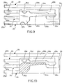
- Figures 7-10 show an alternate embodiment of the invention and like numerals have been applied in Figures 7-10 corresponding to like components described above in relation to Figures 1-6.
- the main difference between the embodiment of Figures 7-10 and the embodiment of Figures 1-6 is the position of tail portions 26a and 30a of second switch terminal 26 and second ground terminal 30.
- the tails of the terminals define input leads to the connector.
- Figure 10 also shows a difference between the embodiment of Figures 7-10 and the embodiment of Figures 1-5. Specifically, an overlapping area 36A between second switch terminal 26 and second ground terminal 30 as highlighted in Figure 10 is slightly larger than the overlapping area 36 in Figure 5.
Landscapes
- Details Of Connecting Devices For Male And Female Coupling (AREA)
- Coupling Device And Connection With Printed Circuit (AREA)
Abstract
Description
Claims (19)
- An electrical switching connector (12) for mounting on a printed circuit board, comprising:a molded dielectric housing (14) defining a receptacle (22);a first switch terminal (24) at least partially overmolded by the housing (14) and including a tail portion (24a) projecting from the housing for connection to the printed circuit board and a contact portion (24c) at said receptacle;a second switch terminal (26) mounted on the housing and including a tail portion (26a) projecting from the housing for connection to the printed circuit board and a flexible contact portion (26c) projecting into the receptacle and engageable with the contact portion (24c) of the first switch terminal (24), whereby a terminal (38) of a complementary mating connector can be inserted into the receptacle (22) in engagement with the flexible contact portion (26c) of the second switch terminal (26) to move said flexible contact portion out of engagement with the contact portion (24c) of the first switch terminal (24); anda pair of ground terminals (28,30) at least partially overmolded by the housing (14) and including tail portions (28a,30a) projecting from the housing for connection to the printed circuit board, each ground terminal (28,30) being juxtaposed alongside one of the switch terminals.
- The electrical switching connector of claim 1 wherein the tail portions (24a,26a,28a,30a) of the said first and second switch terminals (24,26) and said pair of ground terminals (28,30) are coplanar.
- The electrical switching connector of claim 1 wherein the contact portion (24c) of said first switch terminal (24) and body portions (28b,30b) said pair of ground terminals (28,30) are coplanar.
- The electrical switching connector of claim 3 wherein said first switch terminal (24) and said pair of ground terminals (28,30) are stamped and formed of sheet metal material.
- The electrical switching connector of claim 4 wherein the tail portions (24a,26a,28a,30a) of the said first and second switch terminals (24,26) and said pair of ground terminals (28,30) are coplanar in a plane offset from the plane of said contact portion (24c) of the first switch terminal (24) and the body portions (28b,30b) of the pair of ground terminals (28,30).
- The electrical switching connector of claim 1 wherein said pair of ground terminals (28,30) are integrally joined.
- The electrical switching connector of claim 6 wherein said pair of ground terminals (28,30) form the legs of a generally U-shaped configuration with ends of the legs being integrally joined by a cross portion (34) of the U-shaped configuration which surrounds three sides of the contact portion (24c) of the first switch terminal (24).
- The electrical switching connector of claim 1 wherein at least a portion (26d) of said second switch terminal (26) overlaps at least a portion of one (30) of said ground terminals.
- An electrical switching connector (12), comprising:a dielectric housing (14) defining a receptacle (22);a first switch terminal (24) mounted on the housing and including a contact portion (24c) at said receptacle;a second switch terminal (26) mounted on the housing and including a flexible contact portion (26c) projecting into the receptacle and engageable with the contact portion of the first switch terminal, whereby a terminal (38) of a complementary mating connector can be inserted into the receptacle (22) in engagement with the flexible contact portion (26c) of the second switch terminal (26) to move said flexible contact portion (24c) out of engagement wit the contact portion (24c) of the first switch terminal (24);a pair of ground terminals (28,30) juxtaposed alongside one of the switch terminals; andsaid second switch terminal (26) and one of said ground terminals (30) having overlapping capacitor plate portions (26d).
- The electrical switching connector of claim 9 wherein said first switch terminal (24) and said pair of ground terminals (28,30) are stamped and formed of sheet metal material.
- The electrical switching connector of claim 9 wherein the contact portion (24c) of said first switch terminal (24) and body portions (28b,30b) said pair of ground terminals (28,30) are coplanar.
- The electrical switching connector of claim 11 wherein said first switch terminal (24) and said pair of ground terminals (28,30) are stamped and formed of sheet metal material.
- The electrical switching connector of claim 9 wherein said pair of ground terminals (28,30) are integrally joined.
- The electrical switching connector of claim 13 wherein said pair of ground terminals (28,30) form the legs of a generally U-shaped configuration with ends of the legs being integrally joined by a cross portion (34) of the U-shaped configuration which surrounds three sides of the contact portion (24c) of the first switch terminal (24).
- An electrical switching connector (12), comprising:a dielectric housing (14) defining a receptacle (22);a first switch terminal (24) mounted on the housing and including a contact portion (24c) at said receptacle;a second switch terminal (26) mounted on the housing and including a flexible contact portion (26c) projecting into the receptacle and engageable with the contact portion of the first switch terminal, whereby a terminal (38) of a complementary mating connector can be inserted into the receptacle (22) in engagement with the flexible contact portion (26c) of the second switch terminal (26) to move said flexible contact portion out of engagement with the contact portion (24c) of the first switch terminal (24);a pair of ground terminals (28,30) juxtaposed alongside one of the switch terminals; andsaid pair of ground terminals (28,30) forming the legs of a generally U-shaped configuration with ends of the legs being integrally joined by a cross portion (34) of the U-shaped configuration which surrounds three sides of the contact portion (24c) of the first switch terminal (24).
- The electrical switching connector of claim 15 wherein said first switch terminal (24) and said pair of ground terminals (28,30) we stamped and formed of sheet metal material.
- The electrical switching connector of claim 15 wherein the contact portion (24c) of said first switch terminal (24) and body portions (28b,30b) said pair of ground terminals (28,30) are coplanar.
- The electrical switching connector of claim 17 wherein said first switch terminal (24) and said pair of ground terminals (28,30) are stamped and formed of sheet metal material.
- The electrical switching connector of claim 15 wherein at least a portion (26d) of said second switch terminal (26) overlaps at least a portion of one (30) of said ground terminals.
Applications Claiming Priority (2)
| Application Number | Priority Date | Filing Date | Title |
|---|---|---|---|
| US09/264,926 US6142804A (en) | 1999-03-09 | 1999-03-09 | Electrical switching connector |
| US264926 | 1999-03-09 |
Publications (2)
| Publication Number | Publication Date |
|---|---|
| EP1037329A2 true EP1037329A2 (en) | 2000-09-20 |
| EP1037329A3 EP1037329A3 (en) | 2003-05-14 |
Family
ID=23008219
Family Applications (1)
| Application Number | Title | Priority Date | Filing Date |
|---|---|---|---|
| EP00104769A Withdrawn EP1037329A3 (en) | 1999-03-09 | 2000-03-04 | Electrical switching connector |
Country Status (5)
| Country | Link |
|---|---|
| US (1) | US6142804A (en) |
| EP (1) | EP1037329A3 (en) |
| JP (1) | JP3381155B2 (en) |
| SG (1) | SG99861A1 (en) |
| TW (1) | TW449143U (en) |
Families Citing this family (12)
| Publication number | Priority date | Publication date | Assignee | Title |
|---|---|---|---|---|
| DE60014385T2 (en) * | 1999-07-16 | 2006-02-23 | Molex Inc., Lisle | IMPEDANCE-CONNECTED CONNECTOR |
| US6280209B1 (en) | 1999-07-16 | 2001-08-28 | Molex Incorporated | Connector with improved performance characteristics |
| US6503107B1 (en) * | 2000-05-24 | 2003-01-07 | Avaya Technology Corp. | Modular jack having contacting spring leads |
| FI114592B (en) * | 2000-06-30 | 2004-11-15 | Nokia Corp | Coupler and adapter arrangements for connecting external and internal antennas for example to an expansion board |
| US7039417B2 (en) * | 2003-09-25 | 2006-05-02 | Lenovo Pte Ltd | Apparatus, system, and method for mitigating access point data rate degradation |
| US20040092143A1 (en) * | 2002-06-11 | 2004-05-13 | Galen Fromm | High-density, impedance tuned connector |
| WO2004001907A1 (en) * | 2002-06-21 | 2003-12-31 | Molex Incorporated | High-density, impedance-tuned connector having modular construction |
| US6863549B2 (en) * | 2002-09-25 | 2005-03-08 | Molex Incorporated | Impedance-tuned terminal contact arrangement and connectors incorporating same |
| TW568405U (en) * | 2003-03-05 | 2003-12-21 | Hon Hai Prec Ind Co Ltd | Electrical connector |
| WO2009025868A1 (en) | 2007-08-23 | 2009-02-26 | Molex Incorporated | Board mounted electrical connector |
| JP5727765B2 (en) * | 2010-11-30 | 2015-06-03 | 富士通コンポーネント株式会社 | connector |
| US20230198207A1 (en) * | 2021-12-17 | 2023-06-22 | Advanced Micro Devices, Inc. | One esd self-protect method for connector |
Family Cites Families (13)
| Publication number | Priority date | Publication date | Assignee | Title |
|---|---|---|---|---|
| US4708414A (en) * | 1987-01-30 | 1987-11-24 | Albert Lam | Electric wire connector for coaxial cable |
| US4946392A (en) * | 1988-08-09 | 1990-08-07 | Amp Incorporated | Coaxial connector in a housing block |
| JPH031460A (en) * | 1989-05-30 | 1991-01-08 | Amp Japan Ltd | Electric connector |
| JP2906469B2 (en) * | 1989-08-20 | 1999-06-21 | オムロン株式会社 | Shielded wire connector |
| JP2704305B2 (en) * | 1990-03-15 | 1998-01-26 | 日本エー・エム・ピー株式会社 | High frequency connector and method of manufacturing the same |
| US5267868A (en) * | 1992-10-01 | 1993-12-07 | Molex Incorporated | Shielded electrical connector assemblies |
| US5453019A (en) * | 1992-12-07 | 1995-09-26 | The Whitaker Corporation | Internal/external antenna switch connector |
| JP3356476B2 (en) * | 1993-02-23 | 2002-12-16 | 松下電工株式会社 | TV coaxial plug |
| JPH078961U (en) * | 1993-07-14 | 1995-02-07 | 日本エー・エム・ピー株式会社 | Coaxial cable connector |
| US5304069A (en) * | 1993-07-22 | 1994-04-19 | Molex Incorporated | Grounding electrical connectors |
| NL9302115A (en) * | 1993-12-06 | 1995-07-03 | Connector Systems Tech Nv | Coax connector with impedance control. |
| US6011698A (en) * | 1996-11-12 | 2000-01-04 | Delco Electronics Corp. | Circuit protection from radio frequency energy |
| JP3267890B2 (en) * | 1997-03-06 | 2002-03-25 | ヒロセ電機株式会社 | Coaxial connector for antenna switching |
-
1999
- 1999-03-09 US US09/264,926 patent/US6142804A/en not_active Expired - Fee Related
-
2000
- 2000-02-03 SG SG200000649A patent/SG99861A1/en unknown
- 2000-02-14 TW TW089202424U patent/TW449143U/en not_active IP Right Cessation
- 2000-03-02 JP JP2000056703A patent/JP3381155B2/en not_active Expired - Fee Related
- 2000-03-04 EP EP00104769A patent/EP1037329A3/en not_active Withdrawn
Also Published As
| Publication number | Publication date |
|---|---|
| TW449143U (en) | 2001-08-01 |
| JP3381155B2 (en) | 2003-02-24 |
| US6142804A (en) | 2000-11-07 |
| JP2000260535A (en) | 2000-09-22 |
| SG99861A1 (en) | 2003-11-27 |
| EP1037329A3 (en) | 2003-05-14 |
Similar Documents
| Publication | Publication Date | Title |
|---|---|---|
| US6164995A (en) | Impedance tuning in electrical switching connector | |
| KR100478426B1 (en) | Connector with wear-resistant engagement means | |
| US5062811A (en) | Capacitive coupled connector for PCB grounding | |
| US5267868A (en) | Shielded electrical connector assemblies | |
| KR101413531B1 (en) | Electric connector | |
| US7001189B1 (en) | Board mounted power connector | |
| US6086421A (en) | Electrical connector with one-piece shield | |
| US6036545A (en) | Decoupled BNC connector | |
| US6142804A (en) | Electrical switching connector | |
| EP0582726A1 (en) | Modular jack | |
| EP1469565B1 (en) | Coaxial connector with switch | |
| US6361332B1 (en) | Retention system for electrical connectors | |
| US20040266266A1 (en) | Cable end connector assembly with a shield device | |
| NL9302115A (en) | Coax connector with impedance control. | |
| US6386918B1 (en) | Retention element for electrical connector | |
| US5741146A (en) | Coaxial switch | |
| EP1276181B1 (en) | Electrical connector for receiving a plug | |
| US20030100207A1 (en) | Electrical connector with improved electrostatic discharge system | |
| EP1089394A1 (en) | Shielded electrical connector | |
| US5098320A (en) | Shrouded electrical connector | |
| US20060258219A1 (en) | Electrical connector | |
| EP1089395A1 (en) | Shielded electrical connector with a folded wall | |
| EP1071170A1 (en) | Coaxial connector | |
| EP1064702B1 (en) | Decoupled bnc connector | |
| US5239145A (en) | Pin jack |
Legal Events
| Date | Code | Title | Description |
|---|---|---|---|
| PUAI | Public reference made under article 153(3) epc to a published international application that has entered the european phase |
Free format text: ORIGINAL CODE: 0009012 |
|
| AK | Designated contracting states |
Kind code of ref document: A2 Designated state(s): AT BE CH CY DE DK ES FI FR GB GR IE IT LI LU MC NL PT SE |
|
| AX | Request for extension of the european patent |
Free format text: AL;LT;LV;MK;RO;SI |
|
| PUAL | Search report despatched |
Free format text: ORIGINAL CODE: 0009013 |
|
| AK | Designated contracting states |
Designated state(s): AT BE CH CY DE DK ES FI FR GB GR IE IT LI LU MC NL PT SE |
|
| AX | Request for extension of the european patent |
Extension state: AL LT LV MK RO SI |
|
| RIC1 | Information provided on ipc code assigned before grant |
Ipc: 7H 01R 13/703 B Ipc: 7H 01R 13/70 A |
|
| AKX | Designation fees paid |
Designated state(s): DE FR GB IT |
|
| STAA | Information on the status of an ep patent application or granted ep patent |
Free format text: STATUS: THE APPLICATION IS DEEMED TO BE WITHDRAWN |
|
| 18D | Application deemed to be withdrawn |
Effective date: 20031001 |