EP1037320A2 - Connector component - Google Patents
Connector component Download PDFInfo
- Publication number
- EP1037320A2 EP1037320A2 EP00302126A EP00302126A EP1037320A2 EP 1037320 A2 EP1037320 A2 EP 1037320A2 EP 00302126 A EP00302126 A EP 00302126A EP 00302126 A EP00302126 A EP 00302126A EP 1037320 A2 EP1037320 A2 EP 1037320A2
- Authority
- EP
- European Patent Office
- Prior art keywords
- terminal
- connection portion
- electrical wire
- guard member
- connector component
- Prior art date
- Legal status (The legal status is an assumption and is not a legal conclusion. Google has not performed a legal analysis and makes no representation as to the accuracy of the status listed.)
- Granted
Links
- 238000007789 sealing Methods 0.000 claims abstract description 20
- 230000037431 insertion Effects 0.000 claims abstract description 18
- 238000003780 insertion Methods 0.000 claims abstract description 18
- 239000000463 material Substances 0.000 claims abstract description 10
- 238000005452 bending Methods 0.000 claims description 4
- 230000000295 complement effect Effects 0.000 claims description 2
- 238000002788 crimping Methods 0.000 claims description 2
- 230000002452 interceptive effect Effects 0.000 claims description 2
- 230000007704 transition Effects 0.000 claims description 2
- 230000013011 mating Effects 0.000 abstract description 3
- 238000010276 construction Methods 0.000 description 2
- 230000000694 effects Effects 0.000 description 2
- 230000002093 peripheral effect Effects 0.000 description 2
- 239000011248 coating agent Substances 0.000 description 1
- 238000000576 coating method Methods 0.000 description 1
- 239000012858 resilient material Substances 0.000 description 1
Images




Classifications
-
- H—ELECTRICITY
- H01—ELECTRIC ELEMENTS
- H01R—ELECTRICALLY-CONDUCTIVE CONNECTIONS; STRUCTURAL ASSOCIATIONS OF A PLURALITY OF MUTUALLY-INSULATED ELECTRICAL CONNECTING ELEMENTS; COUPLING DEVICES; CURRENT COLLECTORS
- H01R13/00—Details of coupling devices of the kinds covered by groups H01R12/70 or H01R24/00 - H01R33/00
- H01R13/02—Contact members
- H01R13/10—Sockets for co-operation with pins or blades
- H01R13/11—Resilient sockets
-
- H—ELECTRICITY
- H01—ELECTRIC ELEMENTS
- H01R—ELECTRICALLY-CONDUCTIVE CONNECTIONS; STRUCTURAL ASSOCIATIONS OF A PLURALITY OF MUTUALLY-INSULATED ELECTRICAL CONNECTING ELEMENTS; COUPLING DEVICES; CURRENT COLLECTORS
- H01R13/00—Details of coupling devices of the kinds covered by groups H01R12/70 or H01R24/00 - H01R33/00
- H01R13/46—Bases; Cases
- H01R13/52—Dustproof, splashproof, drip-proof, waterproof, or flameproof cases
- H01R13/5205—Sealing means between cable and housing, e.g. grommet
- H01R13/5208—Sealing means between cable and housing, e.g. grommet having at least two cable receiving openings
Definitions
- the present invention relates to a connector component and an electrical terminal, particularly for use in a wiring system of a vehicle, such as an automobile.
- FIG. 7 of the present drawings shows a typical conventional terminal 100 before it is installed in a connector housing 104.
- a resilient sealing member 106 is installed on the connector housing 104.
- the terminal 100 is pressed through a terminal insertion opening 101 formed through the resilient sealing member 106.
- the terminal 100 is formed by cutting and bending an electrically conductive plate material, e.g. by press-working.
- An electrical wire connection portion 103 that is connected with an electrical wire W is formed rearward from the connection portion 102.
- the diameter of the opening 101 is smaller than the outer diameter of the connection portion 102.
- the periphery of the opening 101 is elastically expanded.
- the front edge 107 of the connection portion 102 is folded inward, as shown in Fig. 8. That is, in the conventional terminal 100, the front surface of the terminal fixture 100 is so formed as to prevent the sharp surface from damaging the resilient sealing member 106.
- the resilient sealing member 106 may be damaged.
- a first aspect of the present invention provides a connector component including a connector housing, a resilient sealing member installed on said housing and a terminal.
- the resilient sealing member has an opening for inserting the terminal, in use, into the connector housing in an insertion direction.
- the terminal is formed by cutting and bending an electrically conductive plate material and has a matable connection portion with a front end and a rear end.
- the matable connection portion in use, is connectable to a complementary terminal of another connector component.
- the terminal also includes an electrical wire connection portion.
- the electrical wire connection portion has a front end and a rear end. In use, the electrical wire connection portion is connectable to an electrical wire.
- the rear end of the matable connection portion is joined to the front end of the electrical wire connection portion.
- a top surface of said rear end of said matable connection portion stands clear with respect to a top surface of said front end of said electrical wire connection portion.
- the terminal also has a guard member, which is arranged to guide, in use during insertion of the terminal into and withdrawal of the terminal from said opening, the periphery of the opening between the top surface of the rear end of the matable connection portion and the top surface of the front end of the electrical wire connection portion.
- the guard member has a top surface inclined with respect to the top surface of the rear end of the matable connection portion and the top surface of said front end of the electrical wire connection portion.
- the guard member thereby provides a sloping surface between the top surface of the rear end of the matable connection portion and the top surface of the front end of the electrical wire connection portion.
- the terminal is formed as a single piece of the electrically conductive plate material.
- the guard member is a pair of lateral upward projections, adjacent the front end of the electrical wire connection portion.
- the guard member is a projection joined to the rear end of said matable connection portion.
- the terminal is attached to an electrical wire.
- the electrical wire has an exposed core at the electrical wire connection portion.
- the guard member stands clear with respect to the tip of the core of the electrical wire.
- a second aspect of the present invention provides an electrical terminal having an electrical wire secured to it.
- the terminal has a base, a first portion in the form of a matable connection portion standing up from the base and adapted to connect in use to another terminal, and a second portion in the form of an electrical wire connection portion upstanding from the base and secured to the electrical wire by crimping of material of the terminal.
- the height of the matable connection portion above the base is greater than that of the electrical wire connection portion
- the terminal further has a guard member upstanding from the base between the first and second portions.
- the guard member provides an upward facing portion which constitutes a transition slope sloping downwardly in the direction from the first portion to the second portion over at least part of the extent of the height difference between the first and second portions.
- Fig. 1 is a perspective view showing a terminal before it is pressed into a terminal insertion opening of a resilient sealing member in a first embodiment of the present invention.
- Fig. 2 is a partial perspective view showing the terminal shown in Fig. 1.
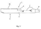
- Fig. 3 is a side view showing the terminal shown in Fig. 1.
- Fig. 4 is a sectional side elevation showing the terminal shown in Fig. 1 before it is pressed into the terminal insertion opening of the resilient sealing member.
- Fig. 5 is a partial perspective view showing a terminal of a second embodiment of the present invention.
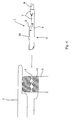
- Fig. 6 is a side view showing the terminal shown in Fig. 5.
- Fig. 7 is a perspective view showing a conventional terminal before it is pressed into a terminal insertion opening of a resilient sealing member.
- Fig. 8 is a perspective view showing a front portion of the terminal of Fig. 7.
- Fig. 9 is a perspective view showing a rear portion of the terminal of Fig. 7.
- Fig. 1 shows a terminal 1 before it is to be installed on a connector housing 2.
- the connector housing 2 has a sealing member 3 formed from a resilient material.
- the sealing member 3 has a plurality of terminal insertion openings 4 into which terminals such as the terminal 1 are pressed, respectively.
- a convexity 11 (see Fig. 4) having a diameter smaller than the outer diameter of an electrical wire W connected to the terminals is formed along the entire inner circumferential surface.
- the convexity 11 is brought into close contact with the outer surface of the coating of the wire W while the convexity 11 is deforming elastically. As a result, a substantially watertight seal is formed.
- the terminal 1 is formed by cutting and bending an electrically conductive plate material.
- the electrically conductive plate material is cut using a press.
- the terminal 1 is installed in the connector housing 2 when connected with one end of the electrical wire W.
- a box-shaped connection portion 6 to be connected, in use of the connecter, with a mating male-side terminal (not shown) is provided at the front side of the terminal 1.
- the outer dimensions of the connection portion 6 are larger than the diameter of the opening 4.
- a wire connection portion 7 that can be connected with the electrical wire W is provided rearward from the connection portion 6.
- An uppermost surface 6A of the connection portion 6 is higher, with respect to the flat base of the terminal, than the wire connection portion 7, i.e. stands clear of the wire connection portion 7.
- a pair of right and left guard members 8 is provided between the uppermost surface 6A of the connection portion 6 and the wire connection portion 7.
- Each guard member 8 extends upward from a side wall 9 and is folded inward (i.e. the right and left guard members 8 are bent towards each other to confront each other) from a position in the vicinity of its center in the height direction. Because the upper end of the guard member 8 is a folded portion, a sharp edge formed in press working is directed downward. The entire upper surface of the guard member 8 inclines downwardly from its front end to its rear end (see Fig. 2).
- the periphery 10 of the opening 4 expands elastically.
- the connection portion 6 has passed the periphery 10 of the opening 4
- the periphery 10 is elastically restored to its original state.
- the periphery 10 is elastically restored to the level of the wire connection portion 7 from the level of the uppermost surface 6A, by contact with the upper side of the guard members 8, so that the periphery 10 is deformed gradually and smoothly as it slides along the slope of the upper surface of the guard members 8.
- the guard members 8 are provided between the uppermost surface 6A of the connection portion 6 and the electric wire connection portion 7, no sharp end contacts the periphery 10 of the opening 4 in pressing the terminal 1 into the opening 4 of the resilient sealing member 3. Thus, risk of damage of the resilient sealing member 3 is less.
- the guard members 8 incline, the edge of the terminal 1 acts progressively on the periphery 10 of the opening 4 when the terminal 1 is inserted into the opening 4 and removed therefrom. Therefore, it is possible to prevent an impact from being applied to the periphery 10, which also reduces risk of damage of the resilient sealing member 3.
- the second embodiment is different from the first embodiment in the construction of the guard member.
- the guard member 12 is formed integrally with the uppermost surface 6A of the connection portion 6.
- the two side portions 13 of the guard member 12 are bent downward and the sharp edge formed during cutting is directed inward.
- the front end 14 of the guard member 12 is bent downward, thus connecting the rear end of the uppermost surface 6A and the front end of the wire connection portion 7 to each other, with the guard member 12 being interposed between the side walls 9.
- the guard member 12 thus provides a sloping upper surface extending obliquely downwardly from the rear end of the upper surface of the connection portion 6.
- the rear end of the guard member 12 is located obliquely upward from the wire core 15 of the electrical wire W connected with the wire connection portion 7 to prevent the core 15 from projecting to the outside of the terminal 1.
- An electrical wire insertion groove 16 is formed at the center of the guard member 12 and is located forward from the rear end of the guard member to prevent the wire W from interfering with the terminal 1 when the wire W is installed on the terminal 1.
- the second embodiment thus constructed has an effect similar to that of the first embodiment.
- the guard member 12 prevents the tip of the core 15 from projecting to the outside of the terminal 1. Therefore, it is possible to prevent the tip of the core 15 from damaging the resilient sealing member 3 when the terminal 1 is pressed into the opening 4.
- the present invention is not limited by the embodiments described and encompasses all embodiments within the spirit and scope of the invention as herein described.
- the female-side terminal is described in the embodiments, but the present invention is also applicable to a male-side terminal.
Landscapes
- Connector Housings Or Holding Contact Members (AREA)
Abstract
Description
Claims (12)
- A connector component including a connector housing (2), a resilient sealing member (3) installed on the housing and a terminal (1) formed by cutting and bending an electrically conductive plate material, the resilient sealing member (3) having an opening (4) for inserting the terminal, in use, into the connector housing in an insertion direction, the terminal having a matable connection portion (6) connectable in use to a complementary terminal of another connector component and an electrical wire connection portion (7) connectable in use to an electrical wire, wherein the rear end of the matable connection portion (6) is joined to the front end of the electrical wire connection portion (7), and in a view perpendicular to said insertion direction, a top surface of the rear end of the matable connection portion stands clear with respect to a top surface of the front end of the electrical wire connection portion;
characterised in that the terminal further includes a guard member (8,12) arranged to guide, in use during insertion of the terminal into and withdrawal of the terminal (1) from the opening (4), the periphery (10) of the opening (4) between the top surface of the rear end of the matable connection portion (6) and the top surface of the front end of the electrical wire connection portion (7). - A connector component according to claim 1, wherein the guard member (8, 12) has a top portion inclined with respect to the top surface (6A) of the rear end of the matable connection portion and the top surface of the front end of the electrical wire connection portion, thereby providing a slope between the top surface of the rear end of the matable connection portion and the top surface of the front end of the electrical wire connection portion.
- A connector component according to claim 1 or claim 2, wherein the terminal (1) is formed as a single piece of the electrically conductive plate material.
- A connector component according to claim 3, wherein the guard member (8) is a pair of lateral upward projections.
- A connector component according to claim 4, wherein each of the upward projections is folded over inwardly to form a fold line at the top edge of the projection.
- A connector component according to claim 3, wherein the guard member (12) is a projection joined to the rear of the matable connection portion (6).
- A connector component according to claim 6, wherein the guard member has two laterally spaced top outer edges formed by respective bend lines.
- A connector component according to claim 6 or 7, wherein the guard member has a rear portion with a cut out recess (16) which is use prevents the end of an electrical wire (W) connected to said connection portion from interfering with said terminal.
- A connector component according to any one of the preceding claims, wherein the terminal (1) is attached to an electrical wire (W), which has an exposed core (15) at the electrical wire connection portion (7), and the guard member (12) has a rear end which stands clear with respect to the tip of the core of the electrical wire whereby, on insertion of the terminal into and withdrawal of the terminal from the opening (4), the periphery (10) of the opening is guided to restrict contact between the periphery of the opening and the tip of the core (15) of the electrical wire.
- An electrical terminal (1) having an electrical wire (W) secured to it, said terminal having a base, a first portion in the form of a matable connection portion (6) standing up from said base and adapted to connect in use to another terminal, a second portion in the form of an electrical wire connection portion (7) upstanding from said base and secured to said electrical wire by crimping of material of the terminal, wherein the height of said matable connection portion above said base is greater than that of said electrical wire connection portion, said terminal further having a guard member (8,12) upstanding from said base between said first and second portions and providing an upward facing portion which constitutes a transition slope sloping downwardly in the direction from said first portion to said second portion over at least part of the extent of the height difference between said first and second portions.
- A terminal according to claim 10, wherein the guard member (8) is a pair of lateral upward projections, each of the upward projections being folded over inwardly to form a fold line at the top edge of the projection.
- A terminal according to claim 10, wherein the guard member (12) is a projection joined to the rear of the matable connection portion (6) and has two laterally spaced top outer edges formed by respective bend lines.
Applications Claiming Priority (6)
| Application Number | Priority Date | Filing Date | Title |
|---|---|---|---|
| JP6999899 | 1999-03-16 | ||
| JP06999899A JP3480693B2 (en) | 1999-03-16 | 1999-03-16 | Female terminal fitting |
| JP09777399A JP3444404B2 (en) | 1999-04-05 | 1999-04-05 | Female terminal fitting |
| JP9777399 | 1999-04-05 | ||
| JP10593099 | 1999-04-13 | ||
| JP10593099A JP3289702B2 (en) | 1999-04-13 | 1999-04-13 | Terminal fitting |
Publications (3)
| Publication Number | Publication Date |
|---|---|
| EP1037320A2 true EP1037320A2 (en) | 2000-09-20 |
| EP1037320A3 EP1037320A3 (en) | 2001-02-28 |
| EP1037320B1 EP1037320B1 (en) | 2005-11-02 |
Family
ID=27300209
Family Applications (1)
| Application Number | Title | Priority Date | Filing Date |
|---|---|---|---|
| EP00302126A Expired - Lifetime EP1037320B1 (en) | 1999-03-16 | 2000-03-15 | Connector component |
Country Status (3)
| Country | Link |
|---|---|
| US (1) | US6287157B1 (en) |
| EP (1) | EP1037320B1 (en) |
| DE (1) | DE60023580T2 (en) |
Families Citing this family (2)
| Publication number | Priority date | Publication date | Assignee | Title |
|---|---|---|---|---|
| JP4381895B2 (en) * | 2004-06-09 | 2009-12-09 | 株式会社オートネットワーク技術研究所 | Connector, cable with connector and manufacturing method thereof |
| US7402089B1 (en) * | 2007-05-04 | 2008-07-22 | Tyco Electronics Corporation | Contact with enhanced transition region |
Family Cites Families (11)
| Publication number | Priority date | Publication date | Assignee | Title |
|---|---|---|---|---|
| US5067916A (en) * | 1990-10-12 | 1991-11-26 | Amp Incorporated | Method for making an electrical contact |
| JP2705046B2 (en) | 1992-06-03 | 1998-01-26 | 矢崎総業株式会社 | Terminal for connector |
| JP2929407B2 (en) * | 1993-06-10 | 1999-08-03 | 矢崎総業株式会社 | Pin terminal |
| JP2803981B2 (en) | 1993-09-17 | 1998-09-24 | 矢崎総業株式会社 | Terminal for electrical connection |
| JP3007781B2 (en) * | 1993-11-30 | 2000-02-07 | 矢崎総業株式会社 | Waterproof rubber plug insertion terminal |
| JP3060891B2 (en) | 1995-05-08 | 2000-07-10 | 住友電装株式会社 | Female terminal fitting |
| JP3093954B2 (en) | 1995-05-26 | 2000-10-03 | 矢崎総業株式会社 | Female terminal fitting |
| JPH09185970A (en) * | 1995-12-28 | 1997-07-15 | Yazaki Corp | Female terminal |
| FR2749443B1 (en) * | 1996-06-03 | 1998-08-21 | Framatome Connectors Int | FEMALE ELECTRIC CONTACT TERMINAL WITH REINFORCED TRANSITION AREA |
| JPH10199587A (en) * | 1997-01-17 | 1998-07-31 | Yazaki Corp | Crimp terminal |
| DE29721752U1 (en) | 1997-12-09 | 1998-02-12 | Siemens AG, 80333 München | Crimp contact for plug systems |
-
2000
- 2000-03-15 EP EP00302126A patent/EP1037320B1/en not_active Expired - Lifetime
- 2000-03-15 DE DE60023580T patent/DE60023580T2/en not_active Expired - Lifetime
- 2000-03-15 US US09/525,463 patent/US6287157B1/en not_active Expired - Lifetime
Also Published As
| Publication number | Publication date |
|---|---|
| EP1037320A3 (en) | 2001-02-28 |
| US6287157B1 (en) | 2001-09-11 |
| DE60023580T2 (en) | 2006-08-10 |
| DE60023580D1 (en) | 2005-12-08 |
| EP1037320B1 (en) | 2005-11-02 |
Similar Documents
| Publication | Publication Date | Title |
|---|---|---|
| US5273459A (en) | Connector feature for improved contact wiping | |
| US5733155A (en) | Female contact | |
| US6394858B1 (en) | Socket contact for electrical connectors | |
| EP0822620B1 (en) | A short-circuiting terminal fitting and a connector comprising such a short-circuiting terminal fitting | |
| EP1271701B1 (en) | Female terminal fitting | |
| US8708759B2 (en) | Terminal fitting and connector | |
| EP1107376A2 (en) | Female connection terminal | |
| EP0977318B1 (en) | Connector with terminal locking mechanism | |
| US20050191912A1 (en) | Female terminal fitting and a blank for a plurality of terminal fittings | |
| JPH08321343A (en) | Female terminal fitting | |
| US6767259B2 (en) | Terminal fitting with outwardly projecting engagement portion for engaging a resin lock and a method of forming the terminal fitting | |
| US7303447B1 (en) | Electrical terminal with anti-snag feature | |
| US5295874A (en) | Weak mating force female terminal | |
| US6183312B1 (en) | Electrical contact | |
| EP0606739A2 (en) | Shielded electrical connector | |
| US5690517A (en) | Receptacle contact | |
| JP4030673B2 (en) | Female terminal of electrical connector | |
| US11245213B2 (en) | Clean body electric terminal | |
| EP1037320B1 (en) | Connector component | |
| EP1577981B1 (en) | A connector and a disengagement jig | |
| EP1619760B1 (en) | A jig and a method for withdrawing a terminal in a connector | |
| EP0938758B1 (en) | Electrical contact | |
| JPH06260238A (en) | Connecting terminal | |
| EP0959531A2 (en) | Single piece electrical receptacle terminal | |
| EP1184941A1 (en) | A female terminal fitting |
Legal Events
| Date | Code | Title | Description |
|---|---|---|---|
| PUAI | Public reference made under article 153(3) epc to a published international application that has entered the european phase |
Free format text: ORIGINAL CODE: 0009012 |
|
| 17P | Request for examination filed |
Effective date: 20000404 |
|
| AK | Designated contracting states |
Kind code of ref document: A2 Designated state(s): DE FR GB IT |
|
| AX | Request for extension of the european patent |
Free format text: AL;LT;LV;MK;RO;SI |
|
| PUAL | Search report despatched |
Free format text: ORIGINAL CODE: 0009013 |
|
| AK | Designated contracting states |
Kind code of ref document: A3 Designated state(s): AT BE CH CY DE DK ES FI FR GB GR IE IT LI LU MC NL PT SE |
|
| AX | Request for extension of the european patent |
Free format text: AL;LT;LV;MK;RO;SI |
|
| RIC1 | Information provided on ipc code assigned before grant |
Free format text: 7H 01R 13/42 A, 7H 01R 13/52 B, 7H 01R 13/422 B |
|
| AKX | Designation fees paid |
Free format text: DE FR GB IT |
|
| 17Q | First examination report despatched |
Effective date: 20030110 |
|
| RIN1 | Information on inventor provided before grant (corrected) |
Inventor name: SAKATANI, ATSUSHI,SUMITOMO WIRING SYST. LTD, Inventor name: MAKITA, YASUMITSU,SUMITOMO WIRING SYST. LTD, Inventor name: SUZUKI, IZUMI Inventor name: FUJITA, SHINYA,SUMITOMO WIRING SYST. LTD Inventor name: FUKATSU, YUKIHIRO |
|
| GRAP | Despatch of communication of intention to grant a patent |
Free format text: ORIGINAL CODE: EPIDOSNIGR1 |
|
| GRAS | Grant fee paid |
Free format text: ORIGINAL CODE: EPIDOSNIGR3 |
|
| GRAA | (expected) grant |
Free format text: ORIGINAL CODE: 0009210 |
|
| AK | Designated contracting states |
Kind code of ref document: B1 Designated state(s): DE FR GB IT |
|
| PG25 | Lapsed in a contracting state [announced via postgrant information from national office to epo] |
Ref country code: IT Free format text: LAPSE BECAUSE OF FAILURE TO SUBMIT A TRANSLATION OF THE DESCRIPTION OR TO PAY THE FEE WITHIN THE PRE;WARNING: LAPSES OF ITALIAN PATENTS WITH EFFECTIVE DATE BEFORE 2007 MAY HAVE OCCURRED AT ANY TIME BEFORE 2007. THE CORRECT EFFECTIVE DATE MAY BE DIFFERENT FROM THE ONE RECORDED.SCRIBED TIME-LIMIT Effective date: 20051102 |
|
| REG | Reference to a national code |
Ref country code: GB Ref legal event code: FG4D |
|
| REF | Corresponds to: |
Ref document number: 60023580 Country of ref document: DE Date of ref document: 20051208 Kind code of ref document: P |
|
| PG25 | Lapsed in a contracting state [announced via postgrant information from national office to epo] |
Ref country code: GB Free format text: LAPSE BECAUSE OF NON-PAYMENT OF DUE FEES Effective date: 20060315 |
|
| PLBE | No opposition filed within time limit |
Free format text: ORIGINAL CODE: 0009261 |
|
| STAA | Information on the status of an ep patent application or granted ep patent |
Free format text: STATUS: NO OPPOSITION FILED WITHIN TIME LIMIT |
|
| 26N | No opposition filed |
Effective date: 20060803 |
|
| GBPC | Gb: european patent ceased through non-payment of renewal fee |
Effective date: 20060315 |
|
| EN | Fr: translation not filed | ||
| PG25 | Lapsed in a contracting state [announced via postgrant information from national office to epo] |
Ref country code: FR Free format text: LAPSE BECAUSE OF FAILURE TO SUBMIT A TRANSLATION OF THE DESCRIPTION OR TO PAY THE FEE WITHIN THE PRESCRIBED TIME-LIMIT Effective date: 20061222 |
|
| PG25 | Lapsed in a contracting state [announced via postgrant information from national office to epo] |
Ref country code: FR Free format text: LAPSE BECAUSE OF FAILURE TO SUBMIT A TRANSLATION OF THE DESCRIPTION OR TO PAY THE FEE WITHIN THE PRESCRIBED TIME-LIMIT Effective date: 20051102 |
|
| REG | Reference to a national code |
Ref country code: DE Ref legal event code: R084 Ref document number: 60023580 Country of ref document: DE |
|
| PGFP | Annual fee paid to national office [announced via postgrant information from national office to epo] |
Ref country code: DE Payment date: 20190305 Year of fee payment: 20 |
|
| REG | Reference to a national code |
Ref country code: DE Ref legal event code: R071 Ref document number: 60023580 Country of ref document: DE |