EP1037240A2 - Magnetic flux concentrator shield for use in overload relay - Google Patents
Magnetic flux concentrator shield for use in overload relay Download PDFInfo
- Publication number
- EP1037240A2 EP1037240A2 EP00105028A EP00105028A EP1037240A2 EP 1037240 A2 EP1037240 A2 EP 1037240A2 EP 00105028 A EP00105028 A EP 00105028A EP 00105028 A EP00105028 A EP 00105028A EP 1037240 A2 EP1037240 A2 EP 1037240A2
- Authority
- EP
- European Patent Office
- Prior art keywords
- magnetic flux
- pole
- shield
- conductor
- concentrating shield
- Prior art date
- Legal status (The legal status is an assumption and is not a legal conclusion. Google has not performed a legal analysis and makes no representation as to the accuracy of the status listed.)
- Granted
Links
Images


Classifications
-
- H—ELECTRICITY
- H01—ELECTRIC ELEMENTS
- H01H—ELECTRIC SWITCHES; RELAYS; SELECTORS; EMERGENCY PROTECTIVE DEVICES
- H01H71/00—Details of the protective switches or relays covered by groups H01H73/00 - H01H83/00
- H01H71/10—Operating or release mechanisms
- H01H71/12—Automatic release mechanisms with or without manual release
- H01H71/123—Automatic release mechanisms with or without manual release using a solid-state trip unit
- H01H71/125—Automatic release mechanisms with or without manual release using a solid-state trip unit characterised by sensing elements, e.g. current transformers
Definitions
- the present invention relates generally to overload relays for electromagnetic contactors, and more particularly to a magnetic flux concentrator shield for use in an overload relay that minimizes cross pole magnetic flux interference in multiple pole contactor applications.
- the present invention provides a magnetic flux concentrating shield that concentrates magnetic flux within a particular pole section while minimizing cross pole magnetic flux interference.
- a magnetic flux concentrating shield comprises a slotted layer having a plurality of poles and a plurality of conductor apertures each capable of receiving a conductor therethrough.
- the shield includes a series of pole shielding slots which are at least partially located between the conductor apertures.
- Each pole has an inner magnetic flux path section on the layer surrounding each conductor aperture. Magnetic flux generated by each conductor is concentrated within each pole and stray magnetic flux generated by each conductor is substantially shielded from the inner magnetic flux path section of an adjacent pole by the pole shielding slots.
- the magnetic flux concentrating shield comprises a plurality of slotted layers. Each slotted layer has a first, second and third conductor apertures.
- the magnetic flux concentrating shield includes a pair of substantially linear pole shielding slots, with each pole shielding slot at least partially located between the conductor apertures, and a contoured pole shielding slot surrounding each inner magnetic flux path section.
- the substantially linear pole shielding slots and the contoured pole shielding slots shield magnetic flux generated by the conductor of one of the poles from the inner magnetic flux path section of another of the poles.
- the magnetic flux concentrating shield comprises a plurality of laminated members.
- the magnetic flux concentrating shield includes a plurality of pole sections, each having an aperture to receive a conductor transversely therethrough.
- Each pole section includes an inner magnetic flux path section having an air gap.
- a magnetic flux sensor is disposed within the air gap of the inner magnetic flux path section.
- the magnetic flux concentrating shield further includes a plurality of pole shielding slots so that when electrical current flows through the conductor of each pole section, a resultant magnetic flux is substantially prevented by the pole shielding slots from straying to the magnetic flux sensor of another pole section. In this manner, cross-pole magnetic flux sensor interference is minimized.
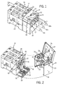
- Starter 10 is shown in perspective view.
- Starter 10 is a multi-phase starter as is used in industrial control applications, such as motor control, and includes contactor 12 and overload relay 14.
- Contactor 12 is an electromagnetic contactor for switching supply current to a motor (not shown), while the overload relay 14 senses and measures the current to the motor, and shuts off or de-energizes the contactor 12 if too much current (overload) is flowing to the motor, thus protecting the motor.
- Overload relay 14 is shown connected with the contactor 12.
- Overload relay 14 accepts a series of conductors 16a, 16b and 16c (shown partially in phantom) through overload relay housing 18, to contactor housing 20 to be secured by lugs 22.
- Overload relay 14 includes a pivotable cover 24 shown in a cover closed position. Overload relay cover 24 further includes an aperture (26 of Fig. 2) such that when cover 24 is in the cover closed position, a locking hasp 28 extends through cover 24 via aperture 26. Other items such as switches 30 and LED indicator 32 may also show through or extend through cover 24 in a similar manner.
- the cover 24 of the overload relay 14 is shown in a cover open position.
- the cover 24 in the cover open position permits visualization of conductors 16a, 16b and 16c (of Fig. 1) as inserted through openings 17 in the overload relay 14 and into the contactor 12 during installation.
- Overload relay housing 18 includes a circular opening through which the rotary knob of a potentiometer 27 connected to a printed circuit board is disposed.
- Potentiometer 27 includes a screwdriver type slot 29 for adjustment of the full load amperage of the particular motor with which the starter 10 is to be used. Potentiometer 27 is covered when cover 24 is in the cover closed position, and a seal inserted through locking hasp 28 prevents unknown later adjustment of potentiometer 27.
- the overload relay 14 includes flexing lock tabs 34, which are each connected to a retaining projection 36.
- retaining projection 36 is T shaped as will be described in further detail with respect to Fig. 6A-6C.
- Retainer projections 36 are insertable into connecting slots 38 within housing wall 40 of contactor 12.
- Each connecting slot 38 preferably has a general T shape with a receiving channel 42 for initially receiving the head 44 of retaining projection 36.
- Receiving channel 42 terminates at one end in a retaining channel 46 which is narrower than the receiving channel 42.
- the retaining projection 36 enters the receiving channel 42 and proceeds downwardly through the retaining channel 46.
- the head 44 of retaining projection 36 is wider then the retaining channel 46, thereby preventing removal of retaining projection 36 through retaining channel 46.
- the retaining projection 36 proceeds downwardly through retaining channel 46 until flexing lock tabs 34 snap under lip 48 of contactor housing wall 40.
- One of ordinary skill will recognize that a different number of retaining projections 36 and connecting slots 38 may be utilized to accomplish a similar connection.
- the contactor 12 includes a platform 50 which is integral with and extends substantially transversely to the plane of contactor wall 40.
- Platform 50 includes supports 52 for supporting contoured coil terminals 54 which extend outwardly from within the contactor 12. Although two contoured coil terminals are shown, it is contemplated that other numbers and arrangements of contoured coil terminals may be utilized.
- the overload relay 14 is placed over the platform 50 to make an electrical connection with contoured coil terminals 54.
- the starter 10 is shown with contactor 12 connected to the overload relay 14.
- the overload relay 14 has a simplified connection to the contactor 12 that includes a snap fit physical connection and an abutting electrical connection, which occur at substantially the same time.
- Contactor 12 includes stationary contacts 56 mounted to the contactor housing 20.
- a moveable contact 58 is mounted to a moveable contact carrier 60.
- the moveable contact 58 is biased toward the stationary contacts 56 by a moveable contact biasing mechanism 62 which is located between the upper enclosure 64 of the moveable contact carrier 60 and the moveable contact 58.
- a magnetic core 66 surrounded by electromagnetic coil 68 in a conventional manner is located on a base portion 70 of contactor housing 20.
- the magnetic core 66 is preferably a solid iron member.
- Electromagnetic coil 68 preferably runs on direct current, and as a result, magnetic core 66 need not be as large as other alternating current electromagnet counterparts having similar power capabilities. The overall size of contactor 12 is therefore reduced.
- magnetic core 66 attracts armature 72 which is connected to moveable contact carrier 60. Moveable contact carrier 60 along with armature 72 are guided towards the magnetic core 66 with guide pin 74.
- Guide pin 74 is press fit or molded securely into moveable contact carrier 60 at one end in an inner surface 76.
- Guide pin 74 is slidable along guide surface 78 within magnetic core 66.
- the single guide pin 74 is centrally disposed and is utilized in providing a smooth and even path for the armature 72 and moveable contactor 60 as it travels to and from the magnetic core 66, preventing the side to side motion during movement caused by uneven movement and partial locking of the moveable contact carrier 60.
- Moveable contact carrier 60 is guided at its upper end 77 by surfaces on the contactor housing 20.
- Guide pin 74 is partially enclosed by a resilient armature return spring 80, which is compressed as the moveable contact carrier 60 moves toward the magnetic core 66.
- Armature return spring 80 biases the moveable contact carrier 60 and armature 72 away from magnetic core 66.
- the combination of the guide pin 74 and the armature return spring 80 helps to provide even downward motion of the moveable contact carrier 60 and helps prevent tilting or locking that may occur during contact closure.
- the moveable contact carrier 60 is guided along guide surface 78 to help provide a more level path to the magnetic core 66.
- lower end 82 of guide pin 74 may be used to cushion or dampen the downward movement at the end of its downward movement, such as in a dash-pot capacity, to help reduce bounce and cushion the closure of the armature 72 with magnetic core 66. Appropriate tolerancing of the guide pin 74 surfaces 78 and housing 20 promotes its use in this capacity.
- a coil extension 84 extends from electromagnetic coil 68.
- coil extension 84 is connected to a contoured coil terminal 54.
- the contoured coil terminal 54 extends outwardly from wall 40 of contactor 12.
- Contoured coil terminal 54 extends onto and rests upon platform 50 so as to position itself to abuttingly engage an electrical conductor or rivet 90 which is part of printed circuit board 92 of the overload relay 14.
- power is supplied to the printed circuit board 92 through a connector 99, which is sized to receive, for example, a JP1 eight pin connector that plugs into the opening 101 of the overload relay 14.
- Electrical power is directed through the printed circuit board 92 so as to be available through rivet 90 to establish an electrical connection to the coil 68 when the contoured coil terminal 54 contacts rivet 90, as occurs when the overload relay 14 is snap fit onto contactor 12.
- Conductor 16a extends through the overload relay 14 into contactor 12 and secured by lugs 22. It is understood that similar connections are made on the opposite side of contactor 12 such that other conductors may be inserted therein and secured by lug 22a to complete a current path to contactor 12.
- overload relay 14 includes a magnetic flux concentrating shield 94. Because of the desirability of manufacturing the magnetic flux concentrating shield 94 by a stamping process, it is preferably made up of thin layers of laminated members 96 secured together. A magnetic flux sensor, such as a Hall sensor 98, is inserted in the air gaps within each pole of the shield. The Hall sensor 98 is connected to printed circuit board 92 by leads 100 and is soldered to the printed circuit board 92, such that it stands off from the printed circuit board 92. The magnetic flux concentrating shield 94 is precisely positioned in the overload relay housing 20 about wall 95 so as to preserve the alignment of Hall sensor 98. Hall sensor 98 and magnetic flux concentrating shield 94, in combination with printed circuit board 92, provide the necessary current measuring circuitry such that the contactor 12 is protected from and can be disabled during overload currents.
- Hall sensor 98 and magnetic flux concentrating shield 94 in combination with printed circuit board 92, provide the necessary current measuring circuitry such that the contactor 12 is protected from and can be disabled during overload currents.
- Fig. 4 is a cross-sectional view of the overload relay 14, and as previously described, includes a magnetic flux concentrating shield 94, which is preferably made up of layers of laminated members 96.
- Locking hasp 28 is shown extending from overload relay 14.
- the locking hasp includes a securing hole 150, in which a tamper resistant seal, such as a wire or lead seal, to prevent unauthorized opening of the cover 24.
- the shield 94 is preferably constructed of a ferrous material, such as steel, that has a lower magnetic reluctance than air and that is receptive to magnetic flux. It is understood that multiple layers 96 are used to achieve the desired magnetic field strength, but a single layer having a greater thickness may also be suitably employed.
- Each layer 96 of shield 94 includes a pole section 130a, 130b and 130c for the reception of conductors 16a, 16b and 16c (of Fig. 4) therethrough respectively. Each pole section will receive generated magnetic flux proportionately to the magnitude and phase of the current passing through that pole section.
- Each pole section 130a, 130b and 130c includes an air gap 132a, 132b, and 132c into which resides a magnetic flux sensor, such as Hall sensors 98a, 98b and 98c.
- Hall sensors are utilized because they are small and fit easily within the space available in the overload relay. Because of the reduced available area, the spacing between individual poles can cause the Hall sensor in one pole to sense (additional) stray flux from an adjacent pole.
- current flows through conductor 16a in a direction passing transversely through member 96. Such a current creates a magnetic flux path in a counter clockwise direction as indicated by arrow 136.
- Flux path 136 for example, is divided between inner flux path 138 on inner flux path section 141, and outer flux path 140 which are divided by U shaped channels 142.
- Outer flux path 140 which provides an avenue for stray magnetic flux, is substantially prevented by pole shielding slot 144a from traveling directly to pole section 130b, but some stray flux does travel via gaps 139.
- the magnetic flux to be measured is concentrated into primary flux path 138, where it must jump through the air gap 132a, and ultimately through Hall sensor 98a.
- pole shielding slots 144a and similarly 144b not only concentrates the magnetic flux to be measured for a particular pole into the Hall sensor for that pole, but also minimizes any stray magnetic flux from taking the elongated path or via gaps 139, thereby shielding the Hall sensors of the adjacent poles from the effects of cross pole magnetic flux interference.
- U-shaped channels 142 it will be recognized, also prevent magnetic flux from influencing Hall sensors 98a, 98b and 98c of adjacent poles, and therefore are considered pole shielding slots as well. Any configuration and placement of the pole shielding slots and U-shaped channels that minimizes magnetic flux transfer between pole sections is contemplated by the present invention.
- pole shielding slots 144a and 144b and three U-shaped channels such as 142 are shown, it will be recognized that more pole shielding slots such as 144a and 144b, and additional channels 142, in various configurations and shapes, may also be utilized to minimize cross-pole magnetic flux interference.
- the amount of magnetic flux lines going across airgaps 132a - 132c is determined by both the length and width of the airgaps.
- the particular shielding and flux concentrating characteristics of the magnetic flux concentrating shield 94 are determined by the placement, configuration and widths of the linear pole shielding slots 144a-144b and U-shaped channels, or contoured pole shielding slots 142.
- the printed circuit board 92 is shown without its associated electrical components except for Hall sensors 98a, 98b, and 98c and JP1 connector 99.
- Hall sensors 98a - 98c are lifted off from the surface 93 of print circuit board 92 by leads 100.
- the Hall sensors 98a-98c stand off from the surface of the printed circuit board 92 so as to be self aligning within the air gaps 132a-132c.
- the printed circuit board 92 and the magnetic flux concentrating shield 94 are both secured within the overload relay housing 20, Fig. 3 and 4, so as not to disturb the precise placement and orientation of the Hall sensors, which must be positioned with their sensitive faces perpendicular to the direction of magnetic flux.
- Printed circuit board 92 also includes openings 101 to receive conductors therethrough.
- multiple layers of magnetic flux concentrating shield 94 are placed such that Hall sensors 98a - 98c are positioned within airgaps 132a - 132c of the magnetic flux concentrating shield 94.
- Conductor apertures 103 correspond with the openings 101 to allow conductors through the printed circuit board 92 and the magnetic flux concentrating shield 94. The net effect is that the current conducted through each of the conductors 16a - 16c produces a magnetic flux through the shield 94 into Hall sensors 98a-c to obtain the current measurement for that conductor.
- the magnetic flux concentrating shield 94 may have many combinations and sizes of pole shielding slots and channels to effectively prevent cross-pole magnetic flux sensor corruption.
Landscapes
- Engineering & Computer Science (AREA)
- Power Engineering (AREA)
- Measuring Instrument Details And Bridges, And Automatic Balancing Devices (AREA)
- Iron Core Of Rotating Electric Machines (AREA)
Abstract
Description
Claims (27)
- A magnetic flux concentrating shield (94) comprising:a slotted layer (96) having a plurality of poles (130a, 130b, 130c) and having a plurality of conductor apertures (103), each conductor aperture (103) capable of receiving a conductor (16a, 16b, 16c) therethrough, and including a series of pole shielding slots (144a, 144b) which are at least partially located between the conductor apertures (103), each pole (130a, 130b, 130c) having an inner magnetic flux path section (141) on the layer surrounding each conductor aperture (103);
wherein magnetic flux generated by each conductor (16a, 16b, 16c) is concentrated within each pole (130a, 130b, 130c) and stray magnetic flux generated by each conductor (16a, 16b, 16c) is substantially shielded from the inner magnetic flux path section (141) of an adjacent pole by the pole shielding slots (144a, 144b). - The magnetic flux concentrating shield (94) of claim 1 wherein the slotted layer (96) includes an air gap (132a, 132b, 132c) within each pole (130a, 130b, 130c) capable of receiving a magnetic flux sensor (98a, 98b, 98c), the airgap (132a, 132b, 132c) located along the inner magnetic flux path section (141) and integral with the conductor aperture (103);
and wherein the pole shielding slots (144a, 144b) minimize the stray magnetic flux of one pole (130a) from entering the inner magnetic flux path section (141) of an adjacent pole (130b) to prevent the stray magnetic flux from being sensed by the magnetic flux sensor (98b) of the adjacent pole (130b). - The magnetic flux concentrating shield (94) of claim 1 wherein the slotted layer (96) is constructed of a material having a lower magnetic reluctance than air.
- The magnetic flux concentrating shield (94) of claim 1 wherein the slotted layer (96) is constructed of a ferrous material.
- The magnetic flux concentrating shield (94) of claim 4 wherein the ferrous material is steel.
- The magnetic flux concentrating shield (94) of claim 1 wherein the slotted layer is stamp manufactured.
- The magnetic flux concentrating shield (94) of claim 1 wherein the slotted layer is laminated.
- The magnetic flux concentrating shield (94) of claim 2 wherein the magnetic flux sensor (98) is a Hall sensor.
- The magnetic flux concentrating shield (94) of claim 1 wherein the slotted layer (96) is connected to and resides in an overload relay (14).
- The magnetic flux concentrating shield (94) of claim 2 wherein the magnetic flux sensor (98) is connected to and operatively associated with a printed circuit (92) for providing power to a contactor (12).
- A magnetic flux concentrating shield (94) comprising a plurality of slotted layers (96), each slotted layer (96) having a first, second, and third conductor apertures (103) corresponding to a first (130a), second (130b), and third (130c) pole, each conductor aperture (103) capable of receiving a conductor (16) therethrough, and having a pair of substantially linear pole shielding slots (144), each linear pole shielding slot (144) at least partially located between the conductor apertures (103), each pole (130) having an inner magnetic flux path section (141) surrounding each conductor aperture (103) and having a contoured pole shielding slot (142) surrounding each inner magnetic flux path section (141); and
wherein magnetic flux generated by the conductor (16) in each of the poles (130) is concentrated within each pole (130) and stray magnetic flux generated by the conductor (16) of one of the poles (130) is substantially shielded from the inner magnetic flux path section (141) of another of the poles (130) by the substantially linear pole shielding slots (144) and the contoured pole shielding slots (142). - The magnetic flux concentrating shield (94) of claim 11 wherein the slotted layer (96) includes an air gap (132) within each pole (130) capable of receiving a magnetic flux sensor (98), the airgap (132) located along the inner magnetic flux path section (141) and integral with the conductor aperture (103);
and wherein the pole shielding slots (142) minimize stray magnetic flux of one pole (130) from entering the inner magnetic flux path section (141) of an adjacent pole (130) to prevent the stray magnetic flux from being sensed by the magnetic flux sensor (98) of the adjacent pole (130). - The magnetic flux concentrating shield (94) of claim 11 wherein the slotted layer (96) is constructed of a material having a lower magnetic reluctance than air.
- The magnetic flux concentrating shield (94) of claim 11 wherein the slotted layer (96) is constructed of a ferrous material.
- The magnetic flux concentrating shield (94) of claim 14 wherein the ferrous material is steel.
- The magnetic flux concentrating shield (94) of claim 11 wherein the slotted layer (96) is stamp manufactured.
- The magnetic flux concentrating shield (94) of claim 11 wherein the slotted layer (96) is laminated.
- The magnetic flux concentrating shield (94) of claim 12 wherein the magnetic flux sensor (98) is a Hall sensor.
- The magnetic flux concentrating shield (94) of claim 11 wherein the slotted layer (96) is connected to and resides in and overload relay (14).
- The magnetic flux concentrating shield (94) of claim 12 wherein the magnetic field sensor (98) is connected to and operatively associated with a printed circuit board (92) for providing power to a contactor (12).
- A magnetic flux concentrating shield (94) comprising:a plurality of pole sections (130), each pole section having an aperture (103) to receive a conductor (16) transversely therethrough and comprising:an inner magnetic flux path section (141) having an air gap (132);a magnetic flux sensor (98) disposed within the air gap (132) of the inner magnetic flux path section (141); anda plurality of pole shielding slots (144), such that when electrical current flows through the conductor (16) of each pole section (130), magnetic flux flowing in each pole section (130) is substantially prevented by the pole shielding slots (144) from reaching the magnetic flux sensor (98) in the inner magnetic flux path section (141) of another of the plurality of pole sections (130), thereby minimizing cross-pole magnetic flux sensor interference.
- The magnetic flux concentrating shield (94) of claim 21 wherein the magnetic flux concentrating shield (94) comprises a plurality of laminated layers (96).
- The magnetic flux concentrating shield (94) of claim 21 wherein the magnetic flux sensor (98) is a Hall sensor.
- The magnetic flux concentrating shield (94) of claim 21 wherein there are three pole sections (130).
- The magnetic flux concentrating shield (94) of claim 21 wherein each pole shielding slot (144) is located between the inner magnetic flux path section (141) of one pole section (130) and the inner magnetic flux path section (141) of another pole section (130).
- The magnetic flux concentrating shield (94) of claim 22 wherein each laminated member (96) is stamp manufactured.
- The magnetic flux concentrating shield (94) of claim 22 wherein the at least one laminated member (96) is connected to and resides in an overload relay (14).
Applications Claiming Priority (2)
| Application Number | Priority Date | Filing Date | Title |
|---|---|---|---|
| US09/267,972 US6121862A (en) | 1999-03-12 | 1999-03-12 | Magnetic flux concentrator shield for use in overload relay |
| US267972 | 1999-03-12 |
Publications (3)
| Publication Number | Publication Date |
|---|---|
| EP1037240A2 true EP1037240A2 (en) | 2000-09-20 |
| EP1037240A3 EP1037240A3 (en) | 2001-06-13 |
| EP1037240B1 EP1037240B1 (en) | 2006-05-03 |
Family
ID=23020908
Family Applications (1)
| Application Number | Title | Priority Date | Filing Date |
|---|---|---|---|
| EP00105028A Expired - Lifetime EP1037240B1 (en) | 1999-03-12 | 2000-03-09 | Magnetic flux concentrator shield for use in overload relay |
Country Status (6)
| Country | Link |
|---|---|
| US (1) | US6121862A (en) |
| EP (1) | EP1037240B1 (en) |
| JP (1) | JP4427769B2 (en) |
| CN (1) | CN1181518C (en) |
| BR (1) | BR0000822A (en) |
| DE (1) | DE60027630T2 (en) |
Cited By (2)
| Publication number | Priority date | Publication date | Assignee | Title |
|---|---|---|---|---|
| EP2383763A1 (en) * | 2010-04-29 | 2011-11-02 | Kissling Elektrotechnik GmbH | Relay, in particular for high voltage use |
| EP3069953A1 (en) * | 2015-03-17 | 2016-09-21 | VolkerRail Nederland BV | Relay state monitoring of railway safety relays |
Families Citing this family (8)
| Publication number | Priority date | Publication date | Assignee | Title |
|---|---|---|---|---|
| US6758146B2 (en) * | 2001-06-29 | 2004-07-06 | The Regents Of The University Of California | Laminated track design for inductrack maglev systems |
| DE102004002014A1 (en) * | 2004-01-14 | 2005-08-11 | Pepperl + Fuchs Gmbh | Angled transducer unit and method for its production, as well as angled switching device and device for the detection of objects |
| CA2600862A1 (en) * | 2005-02-18 | 2007-09-07 | Airpax Corporation | Apparatus comprising circuit breaker with adjunct sensor unit |
| JP5106086B2 (en) * | 2007-12-25 | 2012-12-26 | 株式会社不二工機 | Coil device lead wire drawing structure |
| US8400139B2 (en) | 2010-03-26 | 2013-03-19 | Infineon Technologies Ag | Sensor package having a sensor chip |
| US9341684B2 (en) * | 2013-03-13 | 2016-05-17 | Plures Technologies, Inc. | Magnetic field sensing apparatus and methods |
| JP2017102029A (en) * | 2015-12-02 | 2017-06-08 | アイシン精機株式会社 | Current sensor |
| CN116053062B (en) * | 2023-02-14 | 2026-04-10 | 苏州安昇新材料科技有限公司 | A measuring switch |
Family Cites Families (4)
| Publication number | Priority date | Publication date | Assignee | Title |
|---|---|---|---|---|
| JPH01103133A (en) * | 1987-10-14 | 1989-04-20 | Fanuc Ltd | Non-welded, legged motor structure |
| US4934042A (en) * | 1987-10-16 | 1990-06-19 | Bush Timothy J | Lamination to rotor shaft retention method utilizing spring pins |
| FI87117C (en) * | 1989-03-23 | 1992-11-25 | Abb Stroemberg Kojeet Oy | PROCEDURE FOR THE PRODUCTION OF ELECTRICITY IN THE STEEL FARM |
| FI932122A7 (en) * | 1993-05-11 | 1994-11-12 | Abb Stroemberg Kojeet Oy | Electric current measuring sensor based on flux density measurement and method for tuning it |
-
1999
- 1999-03-12 US US09/267,972 patent/US6121862A/en not_active Expired - Lifetime
-
2000
- 2000-03-09 DE DE60027630T patent/DE60027630T2/en not_active Expired - Lifetime
- 2000-03-09 EP EP00105028A patent/EP1037240B1/en not_active Expired - Lifetime
- 2000-03-10 CN CNB001038877A patent/CN1181518C/en not_active Expired - Fee Related
- 2000-03-10 BR BR0000822-2A patent/BR0000822A/en not_active IP Right Cessation
- 2000-03-13 JP JP2000068865A patent/JP4427769B2/en not_active Expired - Fee Related
Cited By (3)
| Publication number | Priority date | Publication date | Assignee | Title |
|---|---|---|---|---|
| EP2383763A1 (en) * | 2010-04-29 | 2011-11-02 | Kissling Elektrotechnik GmbH | Relay, in particular for high voltage use |
| US8829892B2 (en) | 2010-04-29 | 2014-09-09 | Kissling Elektrotechnik Gmbh | Relay, in particular for the high-current range |
| EP3069953A1 (en) * | 2015-03-17 | 2016-09-21 | VolkerRail Nederland BV | Relay state monitoring of railway safety relays |
Also Published As
| Publication number | Publication date |
|---|---|
| DE60027630T2 (en) | 2007-05-10 |
| US6121862A (en) | 2000-09-19 |
| CN1181518C (en) | 2004-12-22 |
| DE60027630D1 (en) | 2006-06-08 |
| JP4427769B2 (en) | 2010-03-10 |
| JP2000299044A (en) | 2000-10-24 |
| BR0000822A (en) | 2000-10-10 |
| CN1267076A (en) | 2000-09-20 |
| EP1037240A3 (en) | 2001-06-13 |
| EP1037240B1 (en) | 2006-05-03 |
Similar Documents
| Publication | Publication Date | Title |
|---|---|---|
| EP1037241B1 (en) | Electromagnetic contactor with overload relay | |
| EP1981051B1 (en) | Electromagnetic coil apparatus employing a magnetic flux enhancer, and accessory and electrical switching apparatus employing the same | |
| EP1037240B1 (en) | Magnetic flux concentrator shield for use in overload relay | |
| EP0966749B1 (en) | Circuit breaker having hall effect sensors | |
| EP2515125B1 (en) | Current sensor with a magnetic core | |
| KR20080059503A (en) | Earth leakage breaker | |
| KR102830557B1 (en) | Electromagnetic relay | |
| GB2285886A (en) | Circuit breaker | |
| CZ281297B6 (en) | Polarized power relay | |
| EP1981054B1 (en) | Electrical switching apparatus accessory sub-assembly employing reversible coil frame, and accessory and electrical switching apparatus employing the same | |
| US5834934A (en) | Inductive current sensor with reduced influence of spurious gaps and electrical apparatus including it | |
| US5684442A (en) | Electromagnet switching device, especially contactor | |
| EP0409613B1 (en) | Electromagnetic relay having an improved terminal piece structure | |
| EP0541621A1 (en) | A permanent magnet release solenoid for automatic circuit breakers. | |
| EP0390372B1 (en) | Polarized electromagnetic relay | |
| EP1551039B1 (en) | A device for supplying an electronic protection device to be used in a low-voltage circuit breaker | |
| HK1005608B (en) | Polarized electromagnetic relay | |
| US5886600A (en) | Modular thermal magnetic trip unit for rapid circuit interruption | |
| WO2005106505A1 (en) | Appliance terminal | |
| JP3069501B2 (en) | Circuit breaker | |
| JP2604534B2 (en) | Electromagnetic relay | |
| EP4152358B1 (en) | Circuit breaker | |
| WO2025177734A1 (en) | Electromagnetic relay | |
| JP2603618B2 (en) | Overcurrent detection device | |
| KR970002219Y1 (en) | Multi-pole trip check device of circuit breaker |
Legal Events
| Date | Code | Title | Description |
|---|---|---|---|
| PUAI | Public reference made under article 153(3) epc to a published international application that has entered the european phase |
Free format text: ORIGINAL CODE: 0009012 |
|
| AK | Designated contracting states |
Kind code of ref document: A2 Designated state(s): DE FR GB |
|
| AX | Request for extension of the european patent |
Free format text: AL;LT;LV;MK;RO;SI |
|
| PUAL | Search report despatched |
Free format text: ORIGINAL CODE: 0009013 |
|
| AK | Designated contracting states |
Kind code of ref document: A3 Designated state(s): AT BE CH CY DE DK ES FI FR GB GR IE IT LI LU MC NL PT SE |
|
| AX | Request for extension of the european patent |
Free format text: AL;LT;LV;MK;RO;SI |
|
| RIC1 | Information provided on ipc code assigned before grant |
Free format text: 7H 01H 71/12 A, 7G 01R 15/20 B |
|
| 17P | Request for examination filed |
Effective date: 20011212 |
|
| AKX | Designation fees paid |
Free format text: DE FR GB |
|
| GRAP | Despatch of communication of intention to grant a patent |
Free format text: ORIGINAL CODE: EPIDOSNIGR1 |
|
| GRAS | Grant fee paid |
Free format text: ORIGINAL CODE: EPIDOSNIGR3 |
|
| GRAA | (expected) grant |
Free format text: ORIGINAL CODE: 0009210 |
|
| AK | Designated contracting states |
Kind code of ref document: B1 Designated state(s): DE FR GB |
|
| REG | Reference to a national code |
Ref country code: GB Ref legal event code: FG4D |
|
| REF | Corresponds to: |
Ref document number: 60027630 Country of ref document: DE Date of ref document: 20060608 Kind code of ref document: P |
|
| ET | Fr: translation filed | ||
| PLBE | No opposition filed within time limit |
Free format text: ORIGINAL CODE: 0009261 |
|
| STAA | Information on the status of an ep patent application or granted ep patent |
Free format text: STATUS: NO OPPOSITION FILED WITHIN TIME LIMIT |
|
| 26N | No opposition filed |
Effective date: 20070206 |
|
| PGFP | Annual fee paid to national office [announced via postgrant information from national office to epo] |
Ref country code: FR Payment date: 20100318 Year of fee payment: 11 |
|
| PGFP | Annual fee paid to national office [announced via postgrant information from national office to epo] |
Ref country code: GB Payment date: 20100208 Year of fee payment: 11 |
|
| PGFP | Annual fee paid to national office [announced via postgrant information from national office to epo] |
Ref country code: DE Payment date: 20100331 Year of fee payment: 11 |
|
| GBPC | Gb: european patent ceased through non-payment of renewal fee |
Effective date: 20110309 |
|
| REG | Reference to a national code |
Ref country code: FR Ref legal event code: ST Effective date: 20111130 |
|
| PG25 | Lapsed in a contracting state [announced via postgrant information from national office to epo] |
Ref country code: DE Free format text: LAPSE BECAUSE OF NON-PAYMENT OF DUE FEES Effective date: 20111001 Ref country code: FR Free format text: LAPSE BECAUSE OF NON-PAYMENT OF DUE FEES Effective date: 20110331 |
|
| REG | Reference to a national code |
Ref country code: DE Ref legal event code: R119 Ref document number: 60027630 Country of ref document: DE Effective date: 20111001 |
|
| PG25 | Lapsed in a contracting state [announced via postgrant information from national office to epo] |
Ref country code: GB Free format text: LAPSE BECAUSE OF NON-PAYMENT OF DUE FEES Effective date: 20110309 |