EP1037218A2 - Accelerator module for electric vehicle - Google Patents
Accelerator module for electric vehicle Download PDFInfo
- Publication number
- EP1037218A2 EP1037218A2 EP00301756A EP00301756A EP1037218A2 EP 1037218 A2 EP1037218 A2 EP 1037218A2 EP 00301756 A EP00301756 A EP 00301756A EP 00301756 A EP00301756 A EP 00301756A EP 1037218 A2 EP1037218 A2 EP 1037218A2
- Authority
- EP
- European Patent Office
- Prior art keywords
- actuator
- body member
- electrical switch
- electrical
- housing
- Prior art date
- Legal status (The legal status is an assumption and is not a legal conclusion. Google has not performed a legal analysis and makes no representation as to the accuracy of the status listed.)
- Withdrawn
Links
- 230000007246 mechanism Effects 0.000 claims abstract description 85
- 230000001133 acceleration Effects 0.000 claims description 8
- 239000000203 mixture Substances 0.000 claims 1
- 230000000994 depressogenic effect Effects 0.000 description 12
- 230000005540 biological transmission Effects 0.000 description 9
- 238000006073 displacement reaction Methods 0.000 description 9
- 230000003111 delayed effect Effects 0.000 description 8
- 230000000694 effects Effects 0.000 description 7
- 230000008261 resistance mechanism Effects 0.000 description 6
- 230000035939 shock Effects 0.000 description 5
- 238000010348 incorporation Methods 0.000 description 2
- 230000000717 retained effect Effects 0.000 description 2
- 230000000712 assembly Effects 0.000 description 1
- 238000000429 assembly Methods 0.000 description 1
- 230000006378 damage Effects 0.000 description 1
- 238000004519 manufacturing process Methods 0.000 description 1
- 230000002093 peripheral effect Effects 0.000 description 1
- 230000009528 severe injury Effects 0.000 description 1
- 229910000679 solder Inorganic materials 0.000 description 1
- 239000012815 thermoplastic material Substances 0.000 description 1
Images

Classifications
-
- H—ELECTRICITY
- H01—ELECTRIC ELEMENTS
- H01C—RESISTORS
- H01C10/00—Adjustable resistors
- H01C10/30—Adjustable resistors the contact sliding along resistive element
- H01C10/32—Adjustable resistors the contact sliding along resistive element the contact moving in an arcuate path
-
- H—ELECTRICITY
- H01—ELECTRIC ELEMENTS
- H01C—RESISTORS
- H01C10/00—Adjustable resistors
- H01C10/30—Adjustable resistors the contact sliding along resistive element
- H01C10/32—Adjustable resistors the contact sliding along resistive element the contact moving in an arcuate path
- H01C10/36—Adjustable resistors the contact sliding along resistive element the contact moving in an arcuate path structurally combined with switching arrangements
-
- H—ELECTRICITY
- H01—ELECTRIC ELEMENTS
- H01C—RESISTORS
- H01C10/00—Adjustable resistors
- H01C10/30—Adjustable resistors the contact sliding along resistive element
-
- Y—GENERAL TAGGING OF NEW TECHNOLOGICAL DEVELOPMENTS; GENERAL TAGGING OF CROSS-SECTIONAL TECHNOLOGIES SPANNING OVER SEVERAL SECTIONS OF THE IPC; TECHNICAL SUBJECTS COVERED BY FORMER USPC CROSS-REFERENCE ART COLLECTIONS [XRACs] AND DIGESTS
- Y02—TECHNOLOGIES OR APPLICATIONS FOR MITIGATION OR ADAPTATION AGAINST CLIMATE CHANGE
- Y02T—CLIMATE CHANGE MITIGATION TECHNOLOGIES RELATED TO TRANSPORTATION
- Y02T10/00—Road transport of goods or passengers
- Y02T10/60—Other road transportation technologies with climate change mitigation effect
- Y02T10/72—Electric energy management in electromobility
Definitions
- the present invention relates generally to electrical switches and variable electrical resistance mechanisms used in conjunction therewith, and more particularly to an electrical switch and variable electrical resistance mechanism which may be readily incorporated within an accelerator module utilized in connection with electric vehicles.
- Switches and variable electrical resistance mechanisms are utilized in many different applications in order to, in effect, undergo and operatively sense or determine a positional change in response to movement of an operatively associated movable member, and furthermore, to provide or generate a corresponding electrical signal, indicative of such positional change, to an electrical controller.
- An exemplary use of such switches and variable electrical resistance mechanisms is in conjunction with an accelerator pedal of an electric vehicle whereupon depression of the accelerator pedal, the variable electrical resistance mechanism will generate an electrical signal which varies in proportion to the displacement or depression of the accelerator pedal which, of course, corresponds to the degree of acceleration desired by the vehicle operator.
- variable resistance mechanism is mechanically linked to the movable member so as to sense or determine the displacement or movement of the movable member over a predetermined range of movement. More particularly, in the case of utilizing such a system in connection with an accelerator pedal of an electric vehicle, US-A-5920048 discloses a system wherein a potentiometer shaft is operatively connected to an arm or the like which extends from the accelerator pedal so as to be rotated in response to the depression or displacement of the accelerator pedal, and a lever or actuator, carrying a wiper element for defining a wiping contact with respect to constant and variable electrical resistance elements disposed upon a printed circuit board of the electrical assembly, is provided upon the rotary shaft.
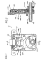
- FIGURES 1 and 2 of the drawings of the present patent application the details and description of the illustrated and disclosed system are only briefly described hereinbelow, and only the relevant component parts of the system have been designated by reference characters, as is necessary to the understanding of such a related system for background purposes.
- the referenced system is generally indicated by the reference character 10 and comprises a normally-open switch 20 which is disposed within a housing 100, and a printed circuit board 300, upon which is disposed a constant electrical resistance element 32 and a variable electrical resistance element 34, which is also disposed within the housing 100.
- An actuator body member 220 which has mounted thereon wiper elements 420 for wipingly engaging the constant electrical resistance element 32 and the variable electrical resistance element 34, is pivotally disposed within the housing 100 as a result of being fixedly mounted upon a rotatable shaft 60 by means of a sleeve portion 230.
- the sleeve portion 230 of the actuator body member 220 is axially or longitudinally fixed upon or with respect to the shaft 60 by means of a collar 70 and a set screw 74, wherein the set screw 74 extends through a threaded bore 72 defined within the collar 70 so as to engage the shaft 60.
- the shaft 60 is, of course, operatively connected to the movable member or accelerator pedal, not shown.
- a torsion spring 170 biases the actuator body member 220 toward the position illustrated in FIGURE 1 such that the actuator body member 220 is normally engaged with an actuator push-button 22 of the normally-open switch 20.
- the deliverance or transmission of actual electrical power to the vehicle drive train be effectively delayed for a predetermined amount of time after the accelerator pedal has undergone a predetermined amount of displacement, movement, or depression by the vehicle operator, wherein such predetermined amount of delayed power transmission time also encompasses a corresponding predetermined amount of pivotal or arcuate movement or displacement of the actuator body member and the wiper elements carried thereon with respect to the constant and variable electrical resistance elements of the printed circuit board prior to the closing of the normally-open switch mechanism.
- such a mode of operation effectively limits any sudden "lurching" of the vehicle when the vehicle is initially moved from a stopped condition or state which would otherwise occur if electrical power is instantaneously transmitted or delivered to the vehicle drive train, without any predetermined delay, when the vehicle accelerator pedal is depressed by the vehicle operator.
- the incorporation of such a delay or operative mechanism within the vehicle comprises, in effect, a safety feature whereby acceleration or movement of the vehicle from a stopped position or condition cannot be inadvertently achieved merely as a result of incidental or limited contact or depression of the vehicle pedal.
- a mode of operation is desirable from an ergonomic point of view.
- such a mode of operation permits adjustability of the voltage signal output level as a function of the movement or depression of the vehicle accelerator pedal, and still further, or fourthly, such a mode of operation or use of such a delay or operative mechanism permits the pedal travel, movement, or depression to be adjusted or compensated for so as to permit the system to be operative in connection with different basic switch mechanisms or assemblies.
- the normally-open switch mechanism will undergo or experience shock or impact forces if the accelerator pedal is suddenly or quickly released whereby the actuator body member is returned to its initial arcuate position and into engagement with the push-button element of the switch mechanism in a substantially rapid manner under the biasing influence of the torsion spring. Under such circumstances, it is possible that the normally-open switch mechanism could undergo or experience breakage, damage, distortion, and the like, and in a similar manner, stresses are likewise imposed upon the solder joints that secure the switch mechanism upon the printed circuit board.
- an actuator body member is pivotally mounted upon the accelerator pedal input shaft, and the actuator body member has a wiper mechanism, comprising wiping elements, mounted thereon for wipingly engaging the variable and constant electrical resistance elements formed upon the printed circuit board, however, in lieu of the non-pivotal, distal end portion of the actuator body member directly engaging the normally-open switch mechanism when the vehicle accelerator pedal is not depressed, the actuator body member of the present invention is provided with a spring-biased plunger mechanism which is movable between two extreme positions depending upon the disposition of the actuator body member as a result of the depression or non-depression of the vehicle accelerator pedal.
- the actuator body member when the vehicle accelerator pedal is initially depressed, the actuator body member is initially rotated or pivoted such that the wiping mechanism thereof begins to wipingly engage the constant and variable electrical resistance elements formed upon the printed circuit board in order to begin transmission of electrical power to the vehicle drive train, however, the spring-biased plunger mechanism is maintained engaged with the switch button of the normally-open switch mechanism under the biasing influence of the plunger mechanism coil spring so as to retain the normally-open switch mechanism in its normally OPEN state whereby actual transmission of electrical power to the vehicle drive train is delayed until the accelerator pedal, and the actuator body member operatively connected thereto, is pivotally moved or displaced a predetermined distance at which time the spring-biased plunger mechanism is physically disengaged from the switch button of the normally-open switch mechanism whereupon the normally-open switch mechanism is now disposed in its CLOSED state and electrical power is able to in fact be transmitted to the vehicle drive train.
- the desired acceleration curve of the electric vehicle is able to be accomplished in an ensured manner.
- the spring-biased plunger mechanism when the actuator body member is rapidly returned to its initial state under the influence of its biasing torsion spring, such as, for example, when the vehicle operator suddenly releases the accelerator pedal from its depressed state, the spring-biased plunger mechanism will absorb any shock or impact forces which would otherwise be impressed upon the switch mechanism thereby eliminating or substantially reducing severe damage to, or stress upon, the switch mechanism and its mounting upon the printed circuit board.
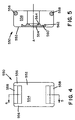
- an actuator 500 is, generally similar to that shown in FIGURES 1 and 2.
- Component parts of it which are similar to corresponding component parts of the actuator disclosed within FIGURES 1 and 2 have been designated by corresponding reference characters except that the reference characters noted in FIGURE 5 are in the 500 series.
- the actuator 500 comprises an actuator body member 520
- the actuator body member 520 comprises a hub portion 522 which is adapted to be rotatably or pivotally disposed within a housing similar to housing 100 of the accelerator module disclosed within FIGURE 1, and which is also adapted to be operatively connected to an accelerator pedal, not shown, of an electric vehicle, also not shown, through means of a connecting shaft or the like similar to shaft 60 of the accelerator module shown in FIGURE 2.
- a torsion spring similar to the torsion spring 170 of the accelerator module of FIGURE 1, is adapted to be operatively associated with the hub portion 522 so as to bias the actuator 500 toward its normal position at which a distal end portion 524 of the actuator body member 520 will normally engage a push-button element, similar to the push-button element 22 of a switch mechanism similar to the switch mechanism 20 of the accelerator module of FIGURE 1, so as to maintain the switch mechanism in its normally-open state wiper member 540, comprising a pair of wiping elements 542,542, is fixedly mounted upon the distal end portion 524 of the actuator body member 520 such that the wiping elements 542,542 can engage constant and variable electrical resistance elements, similar to the constant and variable electrical resistance elements 32 and 34 of FIGURE 1, which are mounted upon a corresponding printed circuit board similar to the printed circuit board 300 of FIGURE 1.
- the basic mode of operation of the acceleration module of the present invention, and including the actuator 500 is essentially the same as that disclosed within the aforenoted US-A-5,920,048 08/603,041, except as follows hereinafter with respect to the delayed closing of the normally-open switch mechanism and the corresponding delayed transmission of electrical power to the vehicle drive train as will now be discussed more fully in detail.
- each support arm 546 has a first proximal end which is integral with the bracket section 544 of the distal end portion 524 of the actuator body member 520, and a second distal end which is provided with a lip portion 548 for a purpose to be discussed hereinafter.
- each of the support arms 546,546 is resiliently flexible.
- a spring-biased plunger or over-travel mechanism is adapted to be mounted upon the support arms 546,546 of the actuator 500 such that the plunger mechanism will be interposed between the distal end portion 524 of the actuator 500 and the push-button element of the normally-open switch of the accelerator module of the present invention, which normally-open switch is similar to the switch 20 shown in FIGURE 1 of the drawings. More particularly, the plunger mechanism of the present invention is generally indicated by the reference character 550 and is seen to comprise a substantially H-shaped housing 552.
- the housing 552 comprises a front wall portion 554 and a pair of oppositely disposed side walls 556,556 which are integral with the front wall portion 554 and extend rearwardly therefrom.
- a pair of vertically spaced, transversely disposed rods or bars 558,558 are integral with the oppositely disposed side walls 556,556 and extend therebetween.
- the rearwardly disposed surface of front wall portion 554 is provided with an annular recessed portion 560, which is best seen in FIGURE 5, and the annular recessed portion 560 in turn defines an annular, radially outer peripheral edge or lip 562 and an annular, radially inner boss section 564.
- the foregoing structure of the front wall portion 554 of the housing 552 serves to seat one end of a coil spring. 566, while the opposite end of the coil spring 566 is seated around a circular boss portion 568 which is formed upon the bracket section 544 of the distal end portion 524 of the actuator body member 520 between the vertically spaced support arms 546,546.
- the plunger mechanism 550 is readily mounted upon the support arms 546,546 of the actuator body member 520 as a result of the transversely extending rods or bars 558,558 of the plunger mechanism 550 initially being engaged with the respective lip portions 548,548 of the arms 546,546 whereby, due to the chamfered configurations of the lip portions 548,548 of the arms 546,546, as well as the aforenoted resilient flexibility of the arms 546,546, the arms 546,546 will in effect be compressed inwardly toward each other so as to permit the rods or bars 558, 558 of the plunger mechanism 550 to in effect be snap-fitted over the lip portions 548,548 of the arms 546,546 whereupon the arms 546,546 can again expand outwardly so as to retain the plunger mechanism 550 thereon at the position shown in FIGURE 3.
- the coil spring 566 serves to respectively bias and retain the plunger mechanism housing 552 toward and at the extended position shown in FIGURE 3 with respect to the distal end portion 524 of the actuator body member 520 and the bracket section 544 thereof when the actuator body member 520 has been rotated or pivoted in the clockwise direction, as indicated by the arrow CW, by means of the vehicle accelerator pedal linkage system, not shown, and after the plunger mechanism 550 has been disengaged from the push-button element of the normally-open switch mechanism so as to permit the normally-open switch mechanism to move to its CLOSED state and thereby provide electrical power to the vehicle drive train.
- the plunger mechanism housing 552 is adapted to move toward the bracket section 544 of the distal end portion 524 of the actuator body member 520, and against the bias of the coil spring 566, and attain or be disposed at the dotted line positions designated by 558', when the coil spring 566 is axially compressed as a result of the actuator body member 520 being rotated or pivoted in the counterclockwise direction, indicated by the arrow CCW, under the influence of the torsion spring, similar to the torsion spring 170 shown in FIGURE 1, when the vehicle accelerator pedal is no longer depressed and after the front wall 554 of the plunger mechanism housing 552 has engaged the push-button element of the normally-open switch mechanism so as to move the normally-open switch mechanism from its CLOSED position or state back to its normally OPEN state.
- bracket section 544 of the distal end portion 524 of the actuator body member 520 is provided with a pair of recessed regions 570,570 for accommodating the transversely disposed rods or bars 558,558 of the plunger mechanism housing 552 when the plunger mechanism 550 is engaged with the push-button element of the normally-open switch mechanism. It is to be further appreciated that when the plunger mechanism 550 is engaged with the normally-open switch mechanism under the influence of the torsion spring biasing the actuator 500 in the counterclockwise direction CCW, the spring-biasing structure of the plunger mechanism housing 552 also serves to absorb shock or impact forces which would otherwise be deleteriously impressed upon the normally-open switch mechanism.
- the objective of the present invention is to permit the actuator 500 to be initially moved a predetermined amount or angular extent in the clockwise direction CW, as a result of the depression of the vehicle accelerator pedal to which the actuator 500 is operatively connected in the aforenoted manner, prior to the closure of the switch mechanism and the transmission of electrical power to the electric vehicle drive train.
- the transmission of electrical power to the vehicle drive train is to be effectively delayed until the actuator 500 has undergone a predetermined amount of rotational or pivotal displacement or movement corresponding to the depression of the vehicle accelerator pedal. In this manner, sudden “lurching" accelerations of the vehicle are effectively limited in their effect.
- the actuator 500 of FIGURE 3 when the actuator 500 of FIGURE 3 is, in effect, inserted into the housing 100 and substituted for the actuator 220 of FIGURE 1, and the actuator 500 is rotatably or pivotally moved in the counterclockwise direction CCW under the biasing influence of the torsion spring 170, such as, for example, when the vehicle accelerator pedal is not depressed or is released from a previously depressed state, the front wall portion 554 of the plunger or over-travel mechanism 550 will initially engage the push-button element 22 of the normally ⁇ open switch mechanism 20 and depress or actuate the same so as to in fact place the switch mechanism 20 in its OPEN state.
- the vehicle accelerator pedal is permitted to be depressed and undergo a predetermined amount of movement or displacement before electrical power is actually transmitted to the vehicle drive train.
- the plunger or over-travel mechanism 550 within the switch actuation system of the electric vehicle accelerator module, the transmission of electrical power to the vehicle drive train is delayed a predetermined amount of time until the accelerator pedal has been depressed to a predetermined degree.
- the movable mounting of the plunger or over-travel mechanism 550 upon the actuator 500 under the biasing influence of the coil spring 566 serves to dampen or absorb any shock or impact forces which would otherwise be impressed upon the push-button element 22 of the normally-open switch mechanism 20, as well as upon the switch mechanism 20 per se and its mountings upon the printed circuit board 300,when the actuator 500 was returned to its normal position under the influence of the torsion spring 170 when the vehicle accelerator pedal was no longer depressed or released.
Landscapes
- Engineering & Computer Science (AREA)
- Microelectronics & Electronic Packaging (AREA)
- Auxiliary Drives, Propulsion Controls, And Safety Devices (AREA)
- Mechanical Control Devices (AREA)
- Control Of Throttle Valves Provided In The Intake System Or In The Exhaust System (AREA)
- Adjustable Resistors (AREA)
- Electric Propulsion And Braking For Vehicles (AREA)
Abstract
Description
Thus, it may be seen that in accordance with the teachings and principles of the present invention, as a result of the incorporation of the plunger or over-travel
Claims (8)
- Apparatus for actuating an electrical switch and providing a variable electrical resistance useable to control electrical power, comprising:a housing;an electrical switch disposed within said housing and having OPEN and CLOSED states;an actuator, comprising a body member, and a cylindrical sleeve member defining a pivot axis within said housing, such that said body member of said actuator is pivotally mounted with respect to said housing and about said axis of said cylindrical sleeve member;spring means for biasing said actuator toward an initial position at which said body member of said actuator engages said electrical switch so as to dispose said electrical switch in said OPEN state, and for permitting pivotal movement of said body member away from said electrical switch and against the biasing force of said spring means in response to movement of said actuator by a movable member so as to permit said body member of said actuator to be disengaged from said electrical switch whereby said electrical switch can change states from said OPEN state to said CLOSED state;a variable electrical resistor disposed within said housing;an electrically conductive wiper mounted upon said body member of said actuator and disposed in contact with said variable electrical resistor disposed within said housing such that when said body member of said actuator is pivoted away from said electrical switch and against said biasing force of said spring means, variable electrical resistance is developed as a function of the disposition of said electrically conductive wiper along said variable electrical resistor; and
means operatively associated with said body member of said actuator and said electrical switch for permitting said body member of said actuator to move a predetermined distance away from said electrical switch, and against said biasing force of said spring means, prior to said body member of said actuator being operatively disengaged from said electrical switch so as to retain said electrical switch in said OPEN state until said body member of said actuator has been moved said predetermined distance away from said electrical switch, and for permitting said electrical switch to change states from said OPEN state to said CLOSED state, and thereby provide said variable electrical resistance, only after said body member of said actuator has been moved said predetermined distance away from said electrical switch. - An apparatus according to Claim 1, wherein:said means operatively associated with said body member of said actuator and said electrical switch comprises a spring-biased plunger overtravel mechanism.
- An apparatus according to Claim 2, wherein:said spring-biased plunger overtravel mechanism is mounted upon said body member of said actuator.
- An apparatus according to Claim 3, wherein:said body member of said actuator comprises a pair of bracket support arms upon which said spring-biased plunger overtravel mechanism is mounted.
- An apparatus according to Claims 2 to 4, wherein said spring-biased plunger overtravel mechanism comprises:a substantially H-shaped housing comprising a front wall portion for engaging said electrical switch, a pair of oppositely disposed side walls integral with said front wall portion, and a pair of transversely disposed rods interconnecting said oppositely disposed side walls and mounted upon said bracket support arms of said body member of said actuator; andspring means, interposed between said body member of said actuator and said front wall portion of said housing, for biasing said housing toward said electrical switch and for retaining said front wall portion of said housing engaged with said electrical switch until said body member of said actuator has been moved said predetermined distance away from said electrical switch so as to be operatively disengaged from said electrical switch.
- An apparatus according to any one of the preceding claims, wherein:said variable electrical resistor comprises a variable resistance element and a constant resistance element; andsaid electrically conductive wiper comprises a first set of electrically conductive prongs disposed in contact with said variable resistance element, and a second set of electrically conductive prongs disposed in contact with said constant resistance element so as to define an electrical connection between said variable resistance element and said constant resistance element.
- An apparatus according to Claim 6, wherein: said variable resistance element and said constant resistance element both comprise conductive ink compositions.
- An apparatus useable to control electrical power for an electric vehicle, comprising an apparatus in accordance with any one of the preceding claims, wherein the pivotal movement of said body member away from said electrical switch and against the biasing force of said spring means is generated in response to movement of said actuator by an acceleration control member of the electric vehicle.
Applications Claiming Priority (2)
| Application Number | Priority Date | Filing Date | Title |
|---|---|---|---|
| US09/270,666 US6184776B1 (en) | 1999-03-16 | 1999-03-16 | Accelerator module for electric vehicle |
| US270666 | 1999-03-16 |
Publications (2)
| Publication Number | Publication Date |
|---|---|
| EP1037218A2 true EP1037218A2 (en) | 2000-09-20 |
| EP1037218A3 EP1037218A3 (en) | 2001-11-21 |
Family
ID=23032282
Family Applications (1)
| Application Number | Title | Priority Date | Filing Date |
|---|---|---|---|
| EP00301756A Withdrawn EP1037218A3 (en) | 1999-03-16 | 2000-03-03 | Accelerator module for electric vehicle |
Country Status (7)
| Country | Link |
|---|---|
| US (1) | US6184776B1 (en) |
| EP (1) | EP1037218A3 (en) |
| JP (1) | JP2000312406A (en) |
| KR (1) | KR100334336B1 (en) |
| CN (1) | CN1112713C (en) |
| CA (1) | CA2298735C (en) |
| TW (1) | TW464882B (en) |
Families Citing this family (3)
| Publication number | Priority date | Publication date | Assignee | Title |
|---|---|---|---|---|
| US6768932B2 (en) * | 2001-12-07 | 2004-07-27 | General Motors Corporation | Wheel motor system |
| US7510801B2 (en) * | 2002-07-12 | 2009-03-31 | Hitachi Maxell, Ltd. | Alkaline battery and method for producing the same |
| JP4200827B2 (en) * | 2003-06-20 | 2008-12-24 | 株式会社デンソー | Impact detection device |
Family Cites Families (28)
| Publication number | Priority date | Publication date | Assignee | Title |
|---|---|---|---|---|
| US3899041A (en) | 1970-10-23 | 1975-08-12 | Charles J Mager | Electric vehicle |
| JPS5018976U (en) | 1973-06-13 | 1975-03-03 | ||
| US4087776A (en) | 1976-12-22 | 1978-05-02 | Drexel Industries, Inc. | Accelerator switch assembly |
| US4123740A (en) | 1977-07-01 | 1978-10-31 | Towmotor Corporation | Adjustable potentiometer in an accelerator control |
| US4199037A (en) | 1978-05-19 | 1980-04-22 | White Bruce D | Electric automobile |
| US4355293A (en) | 1979-10-22 | 1982-10-19 | The Bendix Corporation | Electrical resistance apparatus having integral shorting protection |
| JPS59125806U (en) | 1983-02-12 | 1984-08-24 | アルプス電気株式会社 | 2-axis rotating electrical parts |
| US4604506A (en) | 1985-07-10 | 1986-08-05 | Switches, Inc. | Self-adjusting switch mechanism |
| US4654626A (en) | 1985-08-12 | 1987-03-31 | Tbg Inc. | Dimmer switch |
| US4728923A (en) | 1987-03-12 | 1988-03-01 | Curtis Instruments, Inc. | Steerable wheel direction indicator |
| US4827241A (en) | 1987-10-30 | 1989-05-02 | United Technologies Automotive, Inc. | Combined, in-line spacer and switch, particularly for a vehicle's headlight |
| US4928227A (en) | 1987-11-02 | 1990-05-22 | Ford Motor Company | Method for controlling a motor vehicle powertrain |
| JP2832911B2 (en) | 1988-05-30 | 1998-12-09 | アイシン精機株式会社 | Variable resistor with switch |
| US5023414A (en) | 1989-03-28 | 1991-06-11 | Matsushita Electric Works, Ltd. | Electrical switch for detecting positions of an automatic transmission of an automobile |
| US5086785A (en) | 1989-08-10 | 1992-02-11 | Abrams/Gentille Entertainment Inc. | Angular displacement sensors |
| US5004873A (en) * | 1989-09-20 | 1991-04-02 | Eaton Corporation | Plural set point pressure responsive switching apparatus utilizing a single pressure sensing driver element |
| JP2863234B2 (en) | 1989-12-27 | 1999-03-03 | アイシン・エィ・ダブリュ株式会社 | Electric vehicle |
| DE4028931A1 (en) | 1990-09-12 | 1992-03-19 | Bosch Gmbh Robert | ROTARY ENCODER |
| US5453930A (en) | 1991-02-08 | 1995-09-26 | Nissan Motor Co., Ltd. | Drive system for electric automobiles |
| US5365431A (en) | 1991-04-24 | 1994-11-15 | Aisin Aw Co., Ltd. | Control of electric vehicle motors responsive to detected vehicle speed and required total driving force |
| US5389825A (en) | 1991-04-24 | 1995-02-14 | Aisin Aw Co., Ltd. | System of controlling changeover of an electric power source for an electric motor vehicle |
| JPH05161216A (en) | 1991-12-05 | 1993-06-25 | Honda Motor Co Ltd | Shift control device for electric vehicle |
| JP3379107B2 (en) | 1991-12-10 | 2003-02-17 | アイシン・エィ・ダブリュ株式会社 | Electric motor type vehicle drive system |
| US5359308A (en) | 1993-10-27 | 1994-10-25 | Ael Defense Corp. | Vehicle energy management system using superconducting magnetic energy storage |
| US5440087A (en) * | 1994-01-03 | 1995-08-08 | Texas Instruments Incorporated | Switch system for use with motor vehicle transmissions |
| US5525768A (en) | 1995-02-17 | 1996-06-11 | Texas Instruments Incorporated | Switch system for motor vehicle transmissions |
| GB2302564A (en) * | 1995-06-22 | 1997-01-22 | Lotus Car | I.c.engine throttle valve and fuel control system |
| US5920048A (en) * | 1996-02-16 | 1999-07-06 | Illinois Tool Works Inc. | Electrical switch and variable resistance module for vehicle brake pedal or accelerator and method of operation |
-
1999
- 1999-03-16 US US09/270,666 patent/US6184776B1/en not_active Expired - Lifetime
-
2000
- 2000-02-16 CA CA002298735A patent/CA2298735C/en not_active Expired - Fee Related
- 2000-03-02 TW TW089103712A patent/TW464882B/en not_active IP Right Cessation
- 2000-03-03 EP EP00301756A patent/EP1037218A3/en not_active Withdrawn
- 2000-03-08 CN CN00102896A patent/CN1112713C/en not_active Expired - Fee Related
- 2000-03-08 KR KR1020000011492A patent/KR100334336B1/en not_active Expired - Fee Related
- 2000-03-09 JP JP2000071032A patent/JP2000312406A/en active Pending
Also Published As
| Publication number | Publication date |
|---|---|
| CN1267073A (en) | 2000-09-20 |
| CA2298735C (en) | 2003-08-05 |
| KR20010014542A (en) | 2001-02-26 |
| KR100334336B1 (en) | 2002-04-25 |
| JP2000312406A (en) | 2000-11-07 |
| CN1112713C (en) | 2003-06-25 |
| US6184776B1 (en) | 2001-02-06 |
| EP1037218A3 (en) | 2001-11-21 |
| CA2298735A1 (en) | 2000-09-16 |
| TW464882B (en) | 2001-11-21 |
Similar Documents
| Publication | Publication Date | Title |
|---|---|---|
| EP1334414B1 (en) | Kickdown mechanism for a pedal | |
| EP1117024B1 (en) | Electronic throttle control accelerator pedal mechanism with hysteresis provider | |
| US6474191B1 (en) | Electronic accelerator pedal having a kickdown feature | |
| US5768946A (en) | Pedal with integrated position sensor | |
| US7926384B2 (en) | Accelerator pedal for motorized vehicle | |
| US6860170B2 (en) | Electronic throttle control hysteresis mechanism | |
| EP0466228A2 (en) | Position sensing module | |
| EP1081730B1 (en) | Rocker switch | |
| EP0990782B1 (en) | Accelerator pedal mechanism for vehicle | |
| WO2009089002A1 (en) | Resistance mechanism for a pedal assembly | |
| KR20010053051A (en) | Arrangement of a pedal value generator | |
| US5812050A (en) | Electrical control apparatus with unidirectional tactile indicator | |
| JP2002283871A (en) | Accelerator pedal device | |
| US6184776B1 (en) | Accelerator module for electric vehicle | |
| US5786743A (en) | Fuse cartridge of the type incorporating an operation indicator | |
| US5824979A (en) | Accelerator module | |
| JPH09226543A (en) | Rotational position detection device for rotating member | |
| US5920048A (en) | Electrical switch and variable resistance module for vehicle brake pedal or accelerator and method of operation | |
| MXPA97001156A (en) | Method and device for an electrical switch and variable resistance module | |
| US5097714A (en) | Steering torque detecting apparatus | |
| MXPA00002587A (en) | Accelerator module for electric vehicle | |
| US3432791A (en) | Throttle pedal unit for an industrial truck | |
| EP1942390B1 (en) | Accelerator pedal for motorized vehicle | |
| GB2413375A (en) | Direction and speed control device for a motor vehicle with magnets movable on either side of a sensor | |
| JPH08198068A (en) | Cable device |
Legal Events
| Date | Code | Title | Description |
|---|---|---|---|
| PUAI | Public reference made under article 153(3) epc to a published international application that has entered the european phase |
Free format text: ORIGINAL CODE: 0009012 |
|
| AK | Designated contracting states |
Kind code of ref document: A2 Designated state(s): AT BE CH CY DE DK ES FI FR GB GR IE IT LI LU MC NL PT SE |
|
| AX | Request for extension of the european patent |
Free format text: AL;LT;LV;MK;RO;SI |
|
| PUAL | Search report despatched |
Free format text: ORIGINAL CODE: 0009013 |
|
| RIC1 | Information provided on ipc code assigned before grant |
Free format text: 7B 60R 27/00 A, 7H 01C 10/50 B |
|
| AK | Designated contracting states |
Kind code of ref document: A3 Designated state(s): AT BE CH CY DE DK ES FI FR GB GR IE IT LI LU MC NL PT SE |
|
| AX | Request for extension of the european patent |
Free format text: AL;LT;LV;MK;RO;SI |
|
| 17P | Request for examination filed |
Effective date: 20020425 |
|
| AKX | Designation fees paid |
Free format text: AT BE CH CY DE DK ES FI FR GB GR IE IT LI LU MC NL PT SE |
|
| STAA | Information on the status of an ep patent application or granted ep patent |
Free format text: STATUS: THE APPLICATION HAS BEEN WITHDRAWN |
|
| 18W | Application withdrawn |
Effective date: 20021213 |