EP1037167A2 - System and method for generating and playback of three-dimensional movies - Google Patents
System and method for generating and playback of three-dimensional movies Download PDFInfo
- Publication number
- EP1037167A2 EP1037167A2 EP00301953A EP00301953A EP1037167A2 EP 1037167 A2 EP1037167 A2 EP 1037167A2 EP 00301953 A EP00301953 A EP 00301953A EP 00301953 A EP00301953 A EP 00301953A EP 1037167 A2 EP1037167 A2 EP 1037167A2
- Authority
- EP
- European Patent Office
- Prior art keywords
- viewpoint
- recited
- micropolygons
- frames
- viewer
- Prior art date
- Legal status (The legal status is an assumption and is not a legal conclusion. Google has not performed a legal analysis and makes no representation as to the accuracy of the status listed.)
- Granted
Links
Images



Classifications
-
- G—PHYSICS
- G06—COMPUTING OR CALCULATING; COUNTING
- G06T—IMAGE DATA PROCESSING OR GENERATION, IN GENERAL
- G06T15/00—Three-dimensional [3D] image rendering
-
- G—PHYSICS
- G06—COMPUTING OR CALCULATING; COUNTING
- G06T—IMAGE DATA PROCESSING OR GENERATION, IN GENERAL
- G06T9/00—Image coding
-
- H—ELECTRICITY
- H04—ELECTRIC COMMUNICATION TECHNIQUE
- H04N—PICTORIAL COMMUNICATION, e.g. TELEVISION
- H04N13/00—Stereoscopic video systems; Multi-view video systems; Details thereof
- H04N13/20—Image signal generators
- H04N13/275—Image signal generators from three-dimensional [3D] object models, e.g. computer-generated stereoscopic image signals
- H04N13/279—Image signal generators from three-dimensional [3D] object models, e.g. computer-generated stereoscopic image signals the virtual viewpoint locations being selected by the viewers or determined by tracking
-
- H—ELECTRICITY
- H04—ELECTRIC COMMUNICATION TECHNIQUE
- H04N—PICTORIAL COMMUNICATION, e.g. TELEVISION
- H04N13/00—Stereoscopic video systems; Multi-view video systems; Details thereof
- H04N13/20—Image signal generators
- H04N13/296—Synchronisation thereof; Control thereof
-
- H—ELECTRICITY
- H04—ELECTRIC COMMUNICATION TECHNIQUE
- H04N—PICTORIAL COMMUNICATION, e.g. TELEVISION
- H04N19/00—Methods or arrangements for coding, decoding, compressing or decompressing digital video signals
- H04N19/50—Methods or arrangements for coding, decoding, compressing or decompressing digital video signals using predictive coding
- H04N19/597—Methods or arrangements for coding, decoding, compressing or decompressing digital video signals using predictive coding specially adapted for multi-view video sequence encoding
-
- H—ELECTRICITY
- H04—ELECTRIC COMMUNICATION TECHNIQUE
- H04N—PICTORIAL COMMUNICATION, e.g. TELEVISION
- H04N13/00—Stereoscopic video systems; Multi-view video systems; Details thereof
- H04N13/10—Processing, recording or transmission of stereoscopic or multi-view image signals
- H04N13/189—Recording image signals; Reproducing recorded image signals
-
- H—ELECTRICITY
- H04—ELECTRIC COMMUNICATION TECHNIQUE
- H04N—PICTORIAL COMMUNICATION, e.g. TELEVISION
- H04N13/00—Stereoscopic video systems; Multi-view video systems; Details thereof
- H04N13/10—Processing, recording or transmission of stereoscopic or multi-view image signals
- H04N13/194—Transmission of image signals
-
- H—ELECTRICITY
- H04—ELECTRIC COMMUNICATION TECHNIQUE
- H04N—PICTORIAL COMMUNICATION, e.g. TELEVISION
- H04N13/00—Stereoscopic video systems; Multi-view video systems; Details thereof
- H04N13/20—Image signal generators
- H04N13/286—Image signal generators having separate monoscopic and stereoscopic modes
- H04N13/289—Switching between monoscopic and stereoscopic modes
-
- H—ELECTRICITY
- H04—ELECTRIC COMMUNICATION TECHNIQUE
- H04N—PICTORIAL COMMUNICATION, e.g. TELEVISION
- H04N13/00—Stereoscopic video systems; Multi-view video systems; Details thereof
- H04N13/30—Image reproducers
- H04N13/332—Displays for viewing with the aid of special glasses or head-mounted displays [HMD]
- H04N13/334—Displays for viewing with the aid of special glasses or head-mounted displays [HMD] using spectral multiplexing
-
- H—ELECTRICITY
- H04—ELECTRIC COMMUNICATION TECHNIQUE
- H04N—PICTORIAL COMMUNICATION, e.g. TELEVISION
- H04N13/00—Stereoscopic video systems; Multi-view video systems; Details thereof
- H04N13/30—Image reproducers
- H04N13/332—Displays for viewing with the aid of special glasses or head-mounted displays [HMD]
- H04N13/337—Displays for viewing with the aid of special glasses or head-mounted displays [HMD] using polarisation multiplexing
-
- H—ELECTRICITY
- H04—ELECTRIC COMMUNICATION TECHNIQUE
- H04N—PICTORIAL COMMUNICATION, e.g. TELEVISION
- H04N13/00—Stereoscopic video systems; Multi-view video systems; Details thereof
- H04N13/30—Image reproducers
- H04N13/332—Displays for viewing with the aid of special glasses or head-mounted displays [HMD]
- H04N13/344—Displays for viewing with the aid of special glasses or head-mounted displays [HMD] with head-mounted left-right displays
-
- H—ELECTRICITY
- H04—ELECTRIC COMMUNICATION TECHNIQUE
- H04N—PICTORIAL COMMUNICATION, e.g. TELEVISION
- H04N13/00—Stereoscopic video systems; Multi-view video systems; Details thereof
- H04N13/30—Image reproducers
- H04N13/363—Image reproducers using image projection screens
-
- H—ELECTRICITY
- H04—ELECTRIC COMMUNICATION TECHNIQUE
- H04N—PICTORIAL COMMUNICATION, e.g. TELEVISION
- H04N13/00—Stereoscopic video systems; Multi-view video systems; Details thereof
- H04N13/30—Image reproducers
- H04N13/366—Image reproducers using viewer tracking
-
- H—ELECTRICITY
- H04—ELECTRIC COMMUNICATION TECHNIQUE
- H04N—PICTORIAL COMMUNICATION, e.g. TELEVISION
- H04N13/00—Stereoscopic video systems; Multi-view video systems; Details thereof
- H04N13/30—Image reproducers
- H04N13/398—Synchronisation thereof; Control thereof
Definitions
- This invention relates generally to the field of computer graphics and, more particularly, to three-dimensional (3D) movies.
- Some films have been produced in visual stereo, e.g., with the audience wearing red-blue or polarized glasses.
- head-mounted displays have also allowed viewers to see visual stereo images and films.
- visual stereo has not seen widespread success relative to standard motion pictures. This may be because the stereo-effect is typically limited to a few special effects where a few objects appear to have dimension or "leap out" at the audience. It is likely that the effects that simple visual stereo provides does not outweigh the added cost of production and the hassle of wearing glasses or head-mounted displays to view the image.
- stereo refers to the process of generating two images (i.e., one for the viewer's left eye and another for the viewer's right eye). These images may be referred to herein as stereo component images.
- 3D images and movies go one step further by dynamically changing the viewpoint (ideally on a frame-by-frame basis) for each of the two stereo component images.
- viewpoint ideally on a frame-by-frame basis
- an objected viewed in 3D will not only appear to leap out of the screen, but objects behind it will become obscured or un-obscured as the viewer changes their viewpoint to different positions around the object.
- a traditional stereo image of a globe will appear to have depth, but a tree-dimensional image of the globe will allow the viewer to move around the globe to see more than one side of it.
- head tracking sensors allow graphics systems to recalculate the component images according to where the viewer is in relation to the display device.
- Head tracking may allow a coffee table display to display a 3D football game that viewers can view from almost any angle they desire (e.g., from a bird's eye view directly overhead or from the side of the fifty yard line). To change their viewpoint, viewers simply move around the coffee table.
- the head-tracking sensors will determine where the viewer is and display different component images accordingly.
- head tracking allows panoramic scenes that "wrap-around" viewers without the need for large projection screens that physically surround the viewer. Such head-tracked stereo systems produce a look-around holographic feel qualitatively different from older fixed image displays.
- an efficient system and method for generating and playing back realistic 3D movies with viewer-changeable viewpoints in real-time is desired.
- a system and method capable of reducing the number of calculations to be performed for real-time playback of 3D movies is desired.
- the problems outlined above may at least in part be solved by a system capable of partially rendering frames without relying upon exact viewpoint information.
- the partially rendered frames may be rendered to the extent possible without performing viewpoint-dependent processes, and then compressed and stored to a carrier medium.
- the viewer's possible viewpoints may be restricted (e.g., by defining a viewpoint-limiting volume or region).
- the compressed frames are read as a stream, decompressed, and then rasterized for display.
- the viewer's viewpoint may be determined and used to perform viewpoint-dependent effects such as some lighting and atmospheric effects (e.g., fogging, specular highlighting, and reflections).
- real-time refers to performing an action, task, or process rapidly enough so that the user or viewer will not be substantially distracted by the amount of time taken to perform the task.
- the term “including” means “including, but not limited to.”
- Movies may be thought of as linear story telling.
- the viewer may be like Scrooge (i.e., dragged along by ghosts of Christmas past, present, and future).
- the viewer can see everything in partial or full three dimensions, but generally may not interact with anything (in some embodiments interaction may be allowed).
- the viewer can only go to the places where the ghost goes. Note that this covers not only pre-scripted linear story telling, but also most forms of remote viewing (e.g., live sporting events).
- Linear narratives may be pre-computed using arbitrarily complex animation, physics of motion, shadowing, texturing, and surface modeling techniques, but with the viewpoint-dependent image-rendering deferred until play-back time.
- the geometry may be produced by a geometry shader that outputs micropolygons in world-space via programmable shaders in a realistic rendering package (e.g., Pixar's RenderMan).
- the technology may be used for a number of different applications, including entertainment, scientific visualization, and live 3D television.
- a method for generating three-dimensional movies comprises receiving three-dimensional graphics data representing a scene.
- a viewpoint limitation e.g., a volume or a two-dimensional region with or without orientation limitations
- a viewpoint limitation e.g., a volume or a two-dimensional region with or without orientation limitations
- Partially rendering may comprises performing one or more non-viewpoint dependent (i.e., viewpoint-independent) calculations, such as some lighting calculations (e.g., viewpoint-independent reflections, viewpoint-independent shadows, viewpoint-independent depth of field effects, viewpoint-independent bump mapping, and viewpoint-independent displacement mapping) and tessellating the three-dimensional graphics data into micropolygons to meet one or more predetermined criteria.
- predetermined criteria may include smoothness and micropolygon size in world space. In other embodiments they may also include estimated worst-case micropolygon size in screen space. This estimated worst-case micropolygon size in screen space may be estimated using the distance from a closest permitted viewpoint to each micropolygon and or the worst-case angle from all permitted viewpoints to the micropolygon.
- the micropolygons may be culled by deleting micropolygons that are not visible from any valid viewpoint (i.e., from any viewpoint that satisfies the specified viewpoint limitations.
- the compressed frames are configured to be rasterized in real-time by applying viewpoint-dependent lighting effects. Frames may be stored separately, or they may be reused as a basis for interpolation.
- the specified viewpoint limitation information may also be stored with the frames for use during playback.
- a method for playing back 3D movies may comprise reading a plurality of compressed frames from a carrier medium and then decompressing the compressed frames into a plurality of world-space micro-polygons.
- the viewer may then provide input (e.g., via a head-tracker) as to where the viewpoint should be.
- the micropolygons may be translated to screen-space, and then rasterized to generate a frame for display on a display device.
- the playback unit may also apply viewpoint-dependent lighting, texturing, atmospheric, depth-of-field and or other effects to the micropolygons.
- the rasterization may be performed in real-time, with real-time viewer viewpoint information from head-trackers.
- Compressed audio may also be read with the compressed 3D movie frames, and the audio may be manipulated to reflect the viewer's ear location information (e.g., as provided by a head-tracker).
- a software program and computer system configured to generate three-dimensional movies are also contemplated.
- the software program may comprise a plurality of instructions, wherein the instructions are configured to perform the method of generating 3D movies as described above.
- a software program and playback system configured to playback 3D movies are also contemplated.
- FIG. 1 is a flowchart illustrating one embodiment of a method for generating three-dimensional (3D) movies.
- 3D graphics data representing a scene in a movie is received (step 100).
- the 3D graphics data may include data in a number of different formats.
- three dimensional objects that are part of the scene may be represented as volumes, surfaces, or 3D objects that have been tessellated into a plurality of polygons (e.g., triangles or quadrilaterals).
- the 3D graphics data may also include objects modeled with NURBS (non-uniform rational B-splines), volume elements, subdivision surfaces, meshes and other techniques.
- NURBS non-uniform rational B-splines
- the 3D data may be generated by computer animators, by 3D scanning devices, 3D cameras, 3D digitizers, or other techniques. Depending upon the format in which the 3D graphics data is received, it may be manipulated and transformed before being transformed into a 3D movie.
- real-time viewpoint limitations may be specified (step 102). For example, if a scene in the movie involves a car chase, the viewer's viewpoint may be limited to positions within a police car chasing down a felon fleeing a crime scene. Viewpoint limitations may be specified in a number of different ways. One possible method is specifying a viewpoint limitation volume. Any user-specified viewpoints for the particular scene will be processed as valid. However, if the viewer attempts to change their viewpoint to a position outside the specified limitation volume, then the playback system will force the viewpoint to remain within the predetermined viewpoint volume (more details on the playback system are described further below). This may prevent users from traveling beyond the bounds of the current scene (e.g., through walls). This may also constrain the amount and tessellation of micropolygons, and may also avoid some playback level-of-detail issues.
- limitations on the orientation of the viewpoint may also be specified.
- the viewer may be limited to viewpoint orientations that are directed out the windshield of the police car. This may prevent the viewer from missing an explosion caused by the felon crashing his vehicle into a gasoline station because the viewer was looking out the police car's back window.
- the 3D graphics data may be partially rendered (step 104). As shown by the figure, a number of different processes may be performed as part of partially rendering the 3D graphics data.
- the 3D graphics data may be tessellated into "micropolygons" positioned in object space (step 104A).
- Traditional micropolygons are polygons that have a size near or below a single pixel in screen space.
- some estimations may be performed when tessellating. For example, since micropolygon size is related to the distance from the viewpoint to the micropolygon, the worst case (e.g., the closest) viewpoint may be used when tessellating.
- micropolygon size may also be related to the angle from the viewpoint to the micropolygon.
- a worst case angle may also be used during tessellation.
- the distance and angle may be used separately or in combination to obtain the desired tessellation.
- the use of properly sized micropolygons may improve the realism of the final image produced when compared with using large triangles having areas covering many pixels.
- partial rendering may be performed using a specialized "geometry shader" as described in greater detail below.
- certain micropolygons may be eliminated from the 3D graphic data if they cannot influence visible pixels in the final image (step 104B). For example, if the 3D graphics data contains a tree and the viewer's viewpoint is limited to positions and orientations far above the tree, then the leaves on the lower branches of the tree may be eliminated (i.e., culled) if there is no way the viewer could possibly see them from within the specified viewpoint limitation volume.
- the selected micropolygons that are visible from valid viewpoints may be "mostly lit” and colored (step 104C).
- the micropolygons are "mostly lit” by applying viewpoint-independent lighting and then calculating color information for each micropolygon vertex.
- the micropolygons are referred to as "mostly lit” because some final lighting that is viewpoint-dependent is not applied at this stage. Instead, the final viewpoint dependent component of the lighting (e.g., reflections and specular highlighting) may be applied during playback. This may be changed on a per-frame basis. For example, some frames or scenes may not have any viewpoint-dependent lighting components. Others may have a large number of viewpoint-dependent lighting components.
- the lighting and coloring calculations may be performed in world space (other spaces such as object space may also be used). Included in lighting and color calculations are non-viewpoint-dependent aspects of processes such as texture mapping, most shadowing, some atmospheric effects, some depth of field effects (step 104D). For example, shadows cast by objects are typically viewpoint-independent Thus, in some embodiments the determination of whether a particular light source contributes completely, partially, or not at all to the lighting calculation may be performed at this stage. Viewpoint-dependent components such as specular components can be deferred until playback.
- a calculation is "viewpoint-independent" if the calculation may be performed without reference to the particular viewpoint used by the viewer to view the scene or if the calculation may be performed using only the viewpoint limitations defined for the scene. For example, if the viewpoint is limited to the interior of a car, trees that are in the distant background may have depth of field effects applied during partial rendering. This is because the range of permissible viewpoints is small relative the distance from all possible viewpoints to the trees.
- each individual frame of micropolygons may be compressed (step 106). While a number of different types of compression are possible, geometry compression may be particularly effective for reducing the storage requirements of the micropolygons.
- One such method of geometry compression is described in U.S. Patent No. 5,793,371 entitled “Method and Apparatus for Geometric Compression of Three-Dimensional Graphics Data” issued on August 11, 1998.
- each frame geometry compression With the enormous number of micropolygons generated by each frame geometry compression is useful to be able to reduce the storage requirements for the frames. During play-back, use of compression also greatly reduces the bandwidth necessary for real-time transfer of the frames from disk. To render the compressed geometry in real-time, a compression format that supports hardware decompression may be particularly useful.
- the compressed frames may be output to a carrier medium (step 106).
- the compressed frames may be stored to a computer-readable medium such as RAM, ROM, flash memory, CD-ROM, DVD-ROM, or magnetic disk.
- the frames may be streamed to an array of DVD-ROM recorders (e.g., in a RAID configuration).
- the compressed frames may streamed to a transmission medium such as a computer network line or wireless/satellite link coupled to the internet or broadcast (e.g., VHF or UHF).
- each frame may be stored as a completely separate set of micropolygons.
- portions of some frames may be reused.
- only key frames may be stored completely stored (with intermediate frames being interpolated during playback from key frames).
- step 1 the flowchart depicted in Figure 1 is for explanatory purposes and is not meant to be limiting.
- the steps may be performed in a different order, in parallel (e.g., steps 102 and 104A), or some steps be eliminated (e.g., step 104A or the shadowing of step 104D). Additional steps may also be performed.
- each frame may be stored as a separate compressed object in a separate file (e.g., 3 megabytes in size). For playback, these individual files may then be loaded into a main memory and rendered sequentially.
- each frame may have one or more of the following associated with it: (i) a list of specular light sources, (ii) a viewpoint-limiting volume constraining allowable viewpoints, (iii) a list of specular materials, (iv) an array of compressed geometry objects, and (v) a list of bindings of specular materials and light sources to compressed geometry objects.
- the director/cinematographer may constrain the viewer to a particular region to prevent the viewer from wandering randomly around the virtual set Depending upon the desired effect, such a region may still allow for movement of the viewer's body within a several foot volume for effective stereo display.
- the micropolygon generation need not be uniform in world space (e.g., it may be uniform within a range of tolerances over the limited sighting angles). This allows objects much further away to be tessellated into corresponding larger micropolygons. There is also the opportunity for backface and occlusion culling of objects or portions of objects that are not visible from any allowed view angle on a given frame. This may also be useful when capturing micropolygons from the physical world. 3D cameras need not capture all possible surfaces. Instead, only those potentially visible from the possible view angles may be captured.
- programmable shaders e.g., the surface shader in Pixar's RenderMan application
- surfaces are typically tessellated into polygons (e.g., quadrilaterals or triangles) that meet a specified criteria such as surface curvature, size in screen space, or size in world space.
- render screen space size criteria may also be chosen to generate controlled screen-space-size polygons at playback.
- Typical shader programs then apply a lighting and shading model to these micropolygons, including texture and shadow map look-up, ambient and diffuse lighting calculations, or even radiosity computations. These calculations are typically applied in world space if effects such as displacement shaders are to be supported.
- the micropolygon is projected into screen space, and then rasterized into a z-buffered frame buffer.
- the lit micropolygons are output.
- the print command in Pixar's RenderMan version 3.8 may be used to extract lit micropolygons. Because RenderMan internally defers final mesh connectivity until the rasterization stage, the world space micropolygons generated by this print command are unstitched quad meshes from a higher order surface tessellation. As a post process, the connectivity information may be recomputed and stitching strips may be added to fill in the cracks. This may significantly increase (e.g., double) the number of micropolygons. An intelligent re-tessellator may be used to reduce this overhead.
- a custom shaders that excludes specular computations may be used.
- all opaque surfaces may be set to be very slightly transparent (e.g., 0.9999). Otherwise, the customer shader may differ little from more traditional RenderMan shaders. Effects applied after the micropolygons are extracted (e.g., motion blur and final anti-aliasing), do not show up in the compressed triangle stream. Some view dependent effects, such as reflection or environment mapping, and atmospheric shaders may be excluded or used with care. Transparency may also require particular attention.
- colored micropolygons can be extracted from real world scenes by the use of 3D scanners or cameras.
- real-time 3D capture, conversion to geometry, compression, and transmission may support a form of 3D television. While such geometry acquisition is technically challenging, the same method described herein could be used for playback.
- a geometry compressor may be added as an output processor on the stream of micropolygons generated by RenderMan.
- the triangles may have individual vertex normal and color components. Changes in specular color and specular power may be encoded at a higher object level for use at run-time. The same may be done with the color and placement of the specular light sources. Shadowing of objects from specular lights can be achieved by breaking up each object by the light sources used.
- the compressed geometry may avenge about 7 bytes per triangle. Other sizes and compression ratios are also possible and contemplated. For example, more specialized microtriangle compression techniques may potentially be able to reduce the average microtriangle storage requirement to 2 or 3 bytes.
- One possible rendering configuration may allow a "budget" of one quarter of a million triangles per frame and a playback rate of 24 frames per second. Other values and rates are also contemplated, e.g., 400 thousand triangles per frame and a playback rate of 15 Hz. Assuming each triangle comprises 7 bytes of information, a sustained data transfer rate of about 42 megabytes per second may be useful in such an embodiment.
- One possible method for achieving this transfer rate is an array of three-way interleaved fiber-channel disk drives or possibly an eight-way interleaved array of consumer 5X DVD drives. With a storage capacity of 8.5 megabytes per side, eight DVD disks would support 17 minutes of continuous playback. Of course, faster 3D rendering hardware would change these numbers, but so would better compression techniques. Other configurations and data rates are also possible and contemplated.
- Figure 2 is a flowchart illustrating one embodiment of a method for playing back three-dimensional (3D) movies generated using the method of Figure 1.
- a stream of compressed frames is read and decompressed from a carrier medium (step 120).
- the carrier medium may be either a transmission medium or a computer readable medium.
- the 3D movie may be distributed by across the internet.
- the 3D movie may be distributed as a set of DVD-ROMs that are configured to be simultaneously played back using an array of DVD-ROM players in a RAID configuration.
- the playback system may be configured to receive viewer input as to where the viewer desires their viewpoint to be and (optionally) in which direction they desire to look (step 124).
- This information may be received in a number of different ways.
- a head-tracking sensor may be used to determine the position of a viewer relative to the display device.
- a data glove, wand, joystick, or keyboard may be used to receive information as to where the viewer desires the viewpoint to be positioned.
- Other alternatives include head-tracking using an infrared reflective dot placed on the user's forehead, or using a pair of glasses with head- and or eye-tracking sensors built in.
- One method for using head- and hand-tracking is disclosed in U.S. Patent No.
- the viewer's viewpoint information may be processed along with the previous viewpoint information and the viewpoint limitation read from the carrier medium. For example, hysteresis may be implemented so that subtle movements of the viewer's head (in embodiments utilizing a head-tracker for viewpoint information) do not introduce a "jitter" in the viewpoint.
- the playback system may be configured to compare the calculated viewpoint with the viewpoint limitation information (step 126). If the viewers specified viewpoint for a particular frame is outside the particular frame's viewpoint-limiting volume, then the system may be configured to force or limit the current viewpoint to the closest viewpoint to the viewer's specified viewpoint that meets the frame's specified viewpoint limitations (step 128).
- the playback system may be configured to apply viewpoint-dependent lighting and other viewpoint-dependent optional effects, e.g., atmospheric effects, specular highlights, reflections, and depth of field effects (step 130).
- the amount of processing may varied on a per-frame basis to maintain a minimum desired frame rate.
- the 3D movie producers may also dynamically adjust the amount of viewpoint-dependent processing necessary to maintain a minimum frame rate during playback (e.g., based on a particular minimum playback system configuration).
- Other embodiments of the playback system may be configured to perform as much viewpoint-dependent processing as possible given a predetermined minimum frame rate. If the frame rate is about to drop below the minimum, the playback system may be configured to reduce or eliminate certain viewpoint-dependent effects (e.g., eliminating any reflections).
- the micropolygons may be translated from world-space to screen space based on the viewpoint for the particular frame (step 132).
- the screen-space micropolygons may then be rasterized into a buffer (e.g., a frame buffer or sample buffer) for eventual display (step 136).
- a buffer e.g., a frame buffer or sample buffer
- a number of different displays may be used in the playback system.
- head-mounted displays traditional CRT displays, gas plasma displays, LCD displays, traditional projectors (CRT, LCD, or digital micromirror), or ocular projectors that project images directly onto the viewer's retina may all be used.
- glasses may be worn by viewers to separate the image perceived by each eye.
- the glasses may be passive color filters (e.g., red-blue or red-green), passive polarized, or active (e.g., LCD-shutter type).
- eyeglasses may be optional.
- the micropolygons may be rasterized into a sample buffer that stores multiple samples per display pixel. These samples may then be filtered to generate visually pleasing anti-aliased images.
- some embodiments may be configured to support multiple viewers simultaneously. Each viewer may have their own viewpoint and display. The playback system may be configured to render a different stereo image for each viewer based upon each viewer's particular viewpoint.
- the playback system could perform some viewpoint-dependent occlusion-culling operations to reduce the depth complexity. If objects were compressed at multiple levels-of-detail and decoded in a viewpoint-dependent method, then the constraints on allowable viewing positions could be reduced (at the cost of increasing the amount of data stored and transferred for each frame). Objects with non-specular shading that does not change between frames (e.g., background objects) may be transmitted or stored only at key frames in the file (e.g., similar to MPEG 2 compression I-frames). In other embodiments, some dynamically animated objects may be included in frames to add an additional level of interaction. Branch points to different animation or movie sequences could be also added (e.g., like those used in CD-I). Compressed audio may also be read with the compressed 3D movie frames, and the audio may be manipulated to reflect the viewer's ear locations (as provided by the head-tracker) and to improve realism.
- viewpoint-dependent occlusion-culling operations to reduce the depth complexity. If objects were compressed at multiple levels
- the playback system may be implemented as any of number of different systems, including a computer system, network PC, Internet appliance, a television, including HDTV systems and interactive television systems, personal digital assistants (PDAs), video display glasses, and other devices which are capable of receiving compressed frames and displaying 3D graphics.
- a computer system including a computer system, network PC, Internet appliance, a television, including HDTV systems and interactive television systems, personal digital assistants (PDAs), video display glasses, and other devices which are capable of receiving compressed frames and displaying 3D graphics.
- PDAs personal digital assistants
- video display glasses and other devices which are capable of receiving compressed frames and displaying 3D graphics.
- the playback system 80 comprises a system unit 82 configured to read, decompress, and rasterize compressed 3D movies, and a video monitor or display device 84 coupled to the system unit 82.
- the display device 84 may be any of various types of display monitors (head-mounted or non-head-mounted).
- Optional eyeglasses 90 may be used with non-head-mounted displays.
- the glasses may be passive or active.
- Various input devices may be connected to the computer system, including a keyboard 86 and/or a mouse 88, or other input device (e.g., a trackball, digitizer, tablet, six-degree of freedom input device, head tracker, eye tracker, data glove, body sensors, etc.).
- Application software may be executed by the computer system 80 to read, decompress, and display the 3-D movies on display device 84.
- playback system 80 may comprise an array of storage devices (e.g., a array of eight 5X DVD-ROMs coupled in a RAID configuration) configured to read compressed 3D movies from computer-readable media.
- array of storage devices e.g., a array of eight 5X DVD-ROMs coupled in a RAID configuration
- Other embodiments are possible and contemplated
- Figure 4 illustrates another embodiment of a 3D movie playback system 70.
- the system comprises a head-mounted display device 72, head-tracking sensors 74, and a data glove 76.
- Head mounted display 72 may be coupled to system unit 82 via a fiber optic link 94, or one or more of the following: an electrically-conductive link, an infra-red link, or a wireless (e.g., RF) link.
- system unit 82 does not utilize a storage array. Instead, system unit 82 receives compressed 3D movies via broadcast, internet link, or satellite link (e.g., at a rate of 42 megabytes per second). Other embodiments are possible and contemplated.
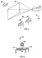
- Figure 5 illustrated another embodiment of a 3D movie playback system 60.
- a digital projector 62 is configured to read, decompress, and rasterize 3D movies.
- Projector 62 is configured to project the 3D movie an a display screen 64.
- Viewers may view display screen 64 with or without optional color filter glasses 68.
- Head-tracking sensor 66 is configured to determine the position of multiple viewer's heads with respect to display screen 64.
- head-tracking sensor 66 may detect viewers' positions by an infra-red reflective dot placed on each viewer's forehead (or on optional glasses 68).
- projector 62 may be configured to perform multiplexing of the image projected onto screen 64. For example, with two viewers, four-way multiplexing may be performed (e.g., viewer 1 left eye, viewer one right eye, viewer 2 left eye, viewer 2 right eye).
- FIG 6 illustrates yet another embodiment of playback system 50.
- playback system 50 is implemented as a coffee table.
- a 3D image 54 is projected from top surface 52 (e.g., by a gas plasma display).
- the 3D image changes to reflect the viewer's current position as detected by integral IR head-tracking sensors 56.
- the representation of image 54 is shown as perceived from viewpoint 58 (i.e., typical gas plasma displays cannot actually project an image into space, so image 58 is viewed from above by looking into top surface 52).
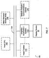
- playback system 80 includes a central processing unit (CPU) 102 coupled to a high-speed memory bus or system bus 104 also referred to as the host bus 104.
- CPU central processing unit
- system bus 104 also referred to as the host bus 104.
- system memory 106 may also be coupled to high-speed bus 104.
- Host processor 102 may comprise one or more processors of varying types, e.g., microprocessors, multi-processors and CPUs.
- the system memory 106 may comprise any combination of different types of memory subsystems, including random access memories, (e.g., static random access memories or "SRAMs”, synchronous dynamic random access memories or “SDRAMs”, and Rambus dynamic access memories or "RDRAM”, among others) and mass storage devices (e.g., DVD-ROM arrays, hard rive arrays, etc.).
- the system bus or host bus 104 may comprise one or more communication or host computer buses (for communication between host processors, CPUs, and memory subsystems) as well as specialized subsystem buses.
- a 3-D graphics system or graphics system 112 may be coupled to the high-speed memory bus 104.
- the 3-D graphics system 112 maybe coupled to the bus 104 by, for example, a crossbar switch or other bus connectivity logic. It is assumed that various other peripheral devices, or other buses, may be connected to the high-speed memory bus 104.
- Optional head-tracker 114 may be coupled to memory bus 104 or directly to graphics system 112.
- Optional network adapter/communications device 116 may also be coupled to bus 104 or directly to graphics system 112. It is noted that the 3-D graphics system may be coupled to one or more of the buses in playback system 80 and/or may be coupled to various types of buses.
- the 3D graphics system may be coupled to a communication port and thereby directly receive graphics data from an external source, e.g., the Internet or a network.
- display device 84 is connected to the 3-D graphics system 112 comprised in playback system 80.
- Host CPU 102 may transfer information to and from the graphics system 112 according to a programmed input/output (I/O) protocol over host bus 104.
- graphics system 112 may access the memory subsystem 106 according to a direct memory access (DMA) protocol or through intelligent bus mastering.
- DMA direct memory access
- the graphics system may receive graphics data from any of various sources, including the host CPU 102 and/or the system memory 106, other memory or computer-readable media (e.g., a DVD-ROM array), or from an external source such as a transmission medium, e.g., a network, the Internet, or a 3D television broadcast.
- sources including the host CPU 102 and/or the system memory 106, other memory or computer-readable media (e.g., a DVD-ROM array), or from an external source such as a transmission medium, e.g., a network, the Internet, or a 3D television broadcast.
- graphics system 112 is depicted as part of computer system 80, graphics system 112 may also be configured as a stand-alone device (e.g., with its own built-in display or link to a projector or head-mounted display). Graphics system 112 may also be configured as a single chip device or as part of a system-on-a-chip or a multi-chip module.
- Figure 8 illustrates yet another embodiment of 3D movie playback system 80.
- playback system 80 comprises input unit 210, which may be a network connection, a bus adapter, bus interface logic, or other input mechanism with which to receive data.
- Input unit 210 may be configured to receive a stream of frames of a compressed 3D movie from a network, a modem, or other storage or transmission device.
- the frames received by input unit 210 are conveyed to decompressor 212 for decompression.
- Decompressor 212 may be a hardware decompressor (preferred) or a software decompressor.
- the decompressed frames are then conveyed to graphics processor 214, which is configured to translate the constituent micropolygons of the decompressed frame from world space to screen space.
- graphics processor applies any viewpoint-dependent lighting effects.
- the completely lit micropolygons are then rasterized by graphics processor 214 into sample/frame buffer 216.
- Display device 84 is refreshed from sample/frame buffer 216.
Landscapes
- Engineering & Computer Science (AREA)
- Multimedia (AREA)
- Signal Processing (AREA)
- General Physics & Mathematics (AREA)
- Theoretical Computer Science (AREA)
- Physics & Mathematics (AREA)
- Computer Graphics (AREA)
- Image Generation (AREA)
- Processing Or Creating Images (AREA)
- Controls And Circuits For Display Device (AREA)
- Testing, Inspecting, Measuring Of Stereoscopic Televisions And Televisions (AREA)
- Compression Or Coding Systems Of Tv Signals (AREA)
- Devices For Indicating Variable Information By Combining Individual Elements (AREA)
Abstract
Description
Claims (43)
- A method for generating three-dimensional movies comprising:receiving three-dimensional graphics data representing a scene;specifying viewpoint limitations for said scene;partially rendering, in a primarily viewpoint-independent manner one or more frames representing said scene;compressing said one or more partially rendered frames; andoutputting said compressed frames to a carrier medium.
- The method as recited in claim 1, wherein said partially rendering comprises tessellating said three-dimensional graphics data into micropolygons to meet one or more predetermined criteria
- The method as recited in claim 2, wherein said one or more predetermined criteria comprise smoothness and predetermined size function in micropolygon size in world space.
- The method as recited in claim 2, wherein said one or more predetermined criteria comprise estimated worst-case micropolygon size in screen space.
- The method as recited in claim 4, wherein said estimated worst-case micropolygon size in screen space is estimated using the distance from a closest permitted viewpoint to a given micropolygon.
- The method as recited in claim 4, said estimated worst-case size in screen space is estimated using the combination of a worst case distance from a closest permitted viewpoint to a given micropolygon and a worst case viewing angle from said viewpoint to a given micropolygon.
- The method as recited in any preceding claim, wherein said partially rendering comprises selecting micropolygons visible from viewpoints complying with said viewpoint limitations.
- The method as recited in any preceding claim, wherein said partially rendering comprises performing a subset of lighting calculations for said selected micropolygons, wherein said subset of lighting calculations are mostly viewpoint-independent
- The method as recited in claim 8, wherein said subset of lighting calculations includes viewpoint-independent shadowing.
- The method as recited in claim 8, wherein said subset of lighting calculations is selected from the group comprising: viewpoint-independent reflections, viewpoint-independent depth of field effects, viewpoint-independent bump mapping, and viewpoint-independent displacement mapping.
- The method as recited in any preceding claim, wherein said specifying viewpoint limitations comprises specifying a viewpoint-limiting volume.
- The method as recited in claim 11, wherein said viewpoint-limiting volume has a depth of zero and is a viewpoint-limiting surface.
- The method as recited in any preceding claim, wherein said specifying viewpoint limitations comprises specifying a set of valid viewpoints and a set of valid viewpoint orientations.
- The method as recited in any preceding claim, wherein said graphics data represents one or more three-dimensional graphics objects, and wherein said method further comprises tessellating said graphics data into a plurality of micropolygons in world space.
- The method as recited in any preceding claim, wherein said rending further comprises applying one or more lighting effects to aid micropolygons, wherein said one or more lighting effects are viewpoint-independent.
- The method as recited in any preceding claim, wherein said carrier medium is selected from the group comprising: transmission media and computer-readable media.
- The method as recited in any preceding claim, wherein said compressed frames are configured to be read in a stream and rasterized in real-time using user-controlled viewpoint information.
- The method as recited in any preceding claim, wherein said compressed frames are configured to be rasterized in real-time by applying viewpoint-dependent lighting effects.
- The method as recited in any preceding claim, wherein each compressed frame comprises separate data.
- The method as recited in any preceding claim, further comprising outputting said viewpoint limitations to said carrier medium.
- The method as recited in any preceding claim, further comprising indicating when one or more portions of a particular frame may be reused in a subsequent frame.
- The method as recited in any preceding claim, wherein only key frames are stored and intermediate frames are interpolated therefrom.
- A method for playing back three-dimensional movies comprising:reading a plurality of compressed frames from a carrier medium;decompressing said compressed frames into a plurality of world-space micro-polygons;inputting viewer-controlled viewpoint information;translating said micropolygons to screen-space;rasterizing said micropolygons to generate a frame; anddisplaying said frame on a display device.
- The method as recited in claim 23, further comprising:applying viewpoint-dependent lighting effects to said micropolygons; andapplying viewpoint-dependent atmospheric effects to said micropolygons.
- The method as recited in any one of claims 23 or 24, further comprising applying viewpoint-dependent texture effects to said micropolygons.
- The method as recited in any one of claims 23 to 25, further comprising applying viewpoint-dependent reflection effects to said micropolygons.
- The method as recited in any one of claims 23 to 26, further comprising comparing said viewer-controlled viewpoint information with viewpoint limitations read from said carrier medium.
- The method as recited in any one of claims 23 to 27, further comprising forcing said viewer-controlled viewpoint information to comply with viewpoint limitations read from said carrier medium.
- The method as recited in any one of claims 23 to 28, wherein said translating, rasterizing, and displaying are performed in real-time.
- The method as recited in any one of claims 23 to 29, wherein each decompressed frame is translated to screen space, rasterized, and displayed in visual stereo.
- The method as recited in any one of claims 23 to 30, further comprising including:reading a stream of compressed audio from said carrier medium;decompressing said stream of compressed audio;processing said decompressed audio to reflect said real-time viewer-controlled ear location information; andplaying back said decompressed and processed audio.
- A software program configured to generate three-dimensional movies, wherein said software program comprises a plurality of instructions, wherein said plurality of instructions are configured to:receive three-dimensional graphics data representing a scene;specify viewpoint limitations for said scene based on viewer input;partially render one or more frames representing said scene;compress said one or more partially-rendered frames; andoutput said compressed frames to a first carrier medium.
- A software program configured to playback three-dimensional movies, wherein said software program comprises a plurality of instructions, wherein said plurality of instructions are configured to:read a plurality of compressed frames from a first carrier medium;decompressing said compressed frames into a plurality of world-space micro-polygons;inputting viewer-controlled viewpoint information;translating said micropolygons to screen-space;rasterizing said micropolygons to generate a frame; anddisplaying said frame on a display device.
- The software program as recited in claim 32 or claim 33, wherein said first carrier medium is selected from the group comprising: (i) computer-readable media and (ii) transmission media.
- The software program as recited in any one of claims 32 to 34 embodied on a second carrier medium.
- The software program as recited in claim 35, wherein said second carrier medium are selected from the group consisting of: (i) computer-readable media and (ii) transmission media.
- The software program as recited in claim 35 or claim 36, wherein the first and second carrier media are the same carrier medium.
- A graphics system configured to playback previously generated three-dimensional movies, said graphics system comprising:an input means for reading a stream of compressed frames from a carrier medium;a decompressor coupled to receive and decompress said compressed frames into a plurality of partially-rendered world-space micro-polygons;a graphics processor coupled to receive said partially-rendered world-space micropolygons; anda sensor coupled to provide said graphics processor with viewer viewpoint information, wherein said graphics processor is configured to translate said world-space micropolygons to screen-space using said viewer viewpoint information, and wherein said graphics processor is configured to rasterize said screen-space micropolygons to generate one or more 3D frames in stereo.
- The system as recited in claim 38, wherein said input means is further configured to receive viewpoint limitation information with said compressed frames, wherein said graphics processor is configured to force said viewer viewpoint information to comply with said viewpoint limitation information.
- The system as recited in claim 38 or claim 39, further comprising a display device and a sample buffer, wherein said sample buffer is coupled between said graphics processor and said display device wherein said sample buffer is super-sampled relative to the number of pixels displayable by said display device.
- The system as recited in any one of claims 38 to 40, wherein said graphics processor is further configured to perform a subset of lighting calculations on said partially-rendered world-space micro-polygons.
- The system as recited in any of claims 38 to 41, wherein said subset of lighting calculations includes all viewpoint-dependent lighting calculations.
- The system as recited in any of claims 38 to 42, wherein said viewpoint-dependent calculations are selected from the group comprising: viewpoint-dependent reflections and viewpoint-dependent depth of field effects.
Applications Claiming Priority (2)
| Application Number | Priority Date | Filing Date | Title |
|---|---|---|---|
| US268397 | 1994-06-30 | ||
| US09/268,397 US6429867B1 (en) | 1999-03-15 | 1999-03-15 | System and method for generating and playback of three-dimensional movies |
Publications (3)
| Publication Number | Publication Date |
|---|---|
| EP1037167A2 true EP1037167A2 (en) | 2000-09-20 |
| EP1037167A3 EP1037167A3 (en) | 2002-12-11 |
| EP1037167B1 EP1037167B1 (en) | 2006-03-01 |
Family
ID=23022826
Family Applications (1)
| Application Number | Title | Priority Date | Filing Date |
|---|---|---|---|
| EP00301953A Expired - Lifetime EP1037167B1 (en) | 1999-03-15 | 2000-03-09 | System and method for generating and playback of three-dimensional movies |
Country Status (7)
| Country | Link |
|---|---|
| US (1) | US6429867B1 (en) |
| EP (1) | EP1037167B1 (en) |
| JP (1) | JP2000353250A (en) |
| AT (1) | ATE319144T1 (en) |
| AU (1) | AU769478B2 (en) |
| CA (1) | CA2300529A1 (en) |
| DE (1) | DE60026233D1 (en) |
Cited By (5)
| Publication number | Priority date | Publication date | Assignee | Title |
|---|---|---|---|---|
| GB2374779A (en) * | 2001-04-20 | 2002-10-23 | Discreet Logic Inc | Cumulative rendering of animated objects |
| US6753864B2 (en) | 2001-04-20 | 2004-06-22 | Autodesk Canada Inc. | Graphical image processing with levels of user access |
| WO2006000368A1 (en) * | 2004-06-24 | 2006-01-05 | Sony Ericsson Mobile Communications Ab | Proximity assisted 3d rendering |
| EP2895824A4 (en) * | 2012-09-17 | 2016-04-20 | Nokia Technologies Oy | Method and apparatus for associating audio objects with content and geo-location |
| CN112044062A (en) * | 2020-08-27 | 2020-12-08 | 腾讯科技(深圳)有限公司 | Game picture rendering method, device, terminal and storage medium |
Families Citing this family (114)
| Publication number | Priority date | Publication date | Assignee | Title |
|---|---|---|---|---|
| US8396328B2 (en) | 2001-05-04 | 2013-03-12 | Legend3D, Inc. | Minimal artifact image sequence depth enhancement system and method |
| US7907793B1 (en) | 2001-05-04 | 2011-03-15 | Legend Films Inc. | Image sequence depth enhancement system and method |
| US6677981B1 (en) * | 1999-12-31 | 2004-01-13 | Stmicroelectronics, Inc. | Motion play-back of still pictures comprising a panoramic view for simulating perspective |
| US7274383B1 (en) | 2000-07-28 | 2007-09-25 | Clairvoyante, Inc | Arrangement of color pixels for full color imaging devices with simplified addressing |
| EP1314149B1 (en) * | 2000-07-28 | 2014-05-21 | Samsung Display Co., Ltd. | Arrangement of color pixels for full color imaging devices with simplified addressing |
| US6760772B2 (en) | 2000-12-15 | 2004-07-06 | Qualcomm, Inc. | Generating and implementing a communication protocol and interface for high data rate signal transfer |
| US8401336B2 (en) | 2001-05-04 | 2013-03-19 | Legend3D, Inc. | System and method for rapid image sequence depth enhancement with augmented computer-generated elements |
| US9286941B2 (en) | 2001-05-04 | 2016-03-15 | Legend3D, Inc. | Image sequence enhancement and motion picture project management system |
| US7184066B2 (en) | 2001-05-09 | 2007-02-27 | Clairvoyante, Inc | Methods and systems for sub-pixel rendering with adaptive filtering |
| US7123277B2 (en) * | 2001-05-09 | 2006-10-17 | Clairvoyante, Inc. | Conversion of a sub-pixel format data to another sub-pixel data format |
| US6894690B2 (en) * | 2001-06-20 | 2005-05-17 | Engineering Technology Associates, Inc. | Method and apparatus for capturing and viewing a sequence of 3-D images |
| US8812706B1 (en) | 2001-09-06 | 2014-08-19 | Qualcomm Incorporated | Method and apparatus for compensating for mismatched delays in signals of a mobile display interface (MDDI) system |
| US7417648B2 (en) | 2002-01-07 | 2008-08-26 | Samsung Electronics Co. Ltd., | Color flat panel display sub-pixel arrangements and layouts for sub-pixel rendering with split blue sub-pixels |
| US7755652B2 (en) | 2002-01-07 | 2010-07-13 | Samsung Electronics Co., Ltd. | Color flat panel display sub-pixel rendering and driver configuration for sub-pixel arrangements with split sub-pixels |
| US6853377B2 (en) * | 2002-06-26 | 2005-02-08 | Nvidia Corporation | System and method of improved calculation of diffusely reflected light |
| US7321682B2 (en) * | 2002-11-12 | 2008-01-22 | Namco Bandai Games, Inc. | Image generation system, image generation method, program, and information storage medium |
| US7680322B2 (en) * | 2002-11-12 | 2010-03-16 | Namco Bandai Games Inc. | Method of fabricating printed material for stereoscopic viewing, and printed material for stereoscopic viewing |
| US20040095348A1 (en) * | 2002-11-19 | 2004-05-20 | Bleiweiss Avi I. | Shading language interface and method |
| US20040196302A1 (en) | 2003-03-04 | 2004-10-07 | Im Moon Hwan | Systems and methods for temporal subpixel rendering of image data |
| US6917368B2 (en) * | 2003-03-04 | 2005-07-12 | Clairvoyante, Inc. | Sub-pixel rendering system and method for improved display viewing angles |
| US7167186B2 (en) | 2003-03-04 | 2007-01-23 | Clairvoyante, Inc | Systems and methods for motion adaptive filtering |
| ATE517500T1 (en) | 2003-06-02 | 2011-08-15 | Qualcomm Inc | GENERATION AND IMPLEMENTATION OF A SIGNAL PROTOCOL AND INTERFACE FOR HIGHER DATA RATES |
| US7290895B2 (en) * | 2003-08-08 | 2007-11-06 | Production Resource Group, L.L.C. | File system for a stage lighting array system |
| AU2004300958A1 (en) | 2003-08-13 | 2005-02-24 | Qualcomm, Incorporated | A signal interface for higher data rates |
| KR100951158B1 (en) | 2003-09-10 | 2010-04-06 | 콸콤 인코포레이티드 | High-speed data interface |
| EP1680904A1 (en) | 2003-10-15 | 2006-07-19 | QUALCOMM Incorporated | High data rate interface |
| TWI401601B (en) | 2003-10-29 | 2013-07-11 | Qualcomm Inc | Method and system for a mobile display digital interface system and computer program product |
| CN101729205A (en) | 2003-11-12 | 2010-06-09 | 高通股份有限公司 | High data rate interface with improved link control |
| RU2006122542A (en) | 2003-11-25 | 2008-01-10 | Квэлкомм Инкорпорейтед (US) | HIGH-SPEED DATA TRANSFER INTERFACE WITH IMPROVED COMMUNICATION LINK SYNCHRONIZATION |
| CA2731269C (en) | 2003-12-08 | 2013-01-08 | Qualcomm Incorporated | High data rate interface with improved link synchronization |
| US7224326B2 (en) * | 2004-03-03 | 2007-05-29 | Volo, Llc | Virtual reality system |
| EP2309695A1 (en) * | 2004-03-10 | 2011-04-13 | Qualcomm Incorporated | High data rate interface apparatus and method |
| WO2005091593A1 (en) | 2004-03-17 | 2005-09-29 | Qualcomm Incorporated | High data rate interface apparatus and method |
| US8645566B2 (en) | 2004-03-24 | 2014-02-04 | Qualcomm Incorporated | High data rate interface apparatus and method |
| US8650304B2 (en) | 2004-06-04 | 2014-02-11 | Qualcomm Incorporated | Determining a pre skew and post skew calibration data rate in a mobile display digital interface (MDDI) communication system |
| AU2005253592B2 (en) | 2004-06-04 | 2009-02-05 | Qualcomm Incorporated | High data rate interface apparatus and method |
| US8159526B2 (en) * | 2004-09-17 | 2012-04-17 | Seiko Epson Corporation | Stereoscopic image display system |
| US8539119B2 (en) | 2004-11-24 | 2013-09-17 | Qualcomm Incorporated | Methods and apparatus for exchanging messages having a digital data interface device message format |
| US8692838B2 (en) | 2004-11-24 | 2014-04-08 | Qualcomm Incorporated | Methods and systems for updating a buffer |
| US8699330B2 (en) | 2004-11-24 | 2014-04-15 | Qualcomm Incorporated | Systems and methods for digital data transmission rate control |
| US8873584B2 (en) | 2004-11-24 | 2014-10-28 | Qualcomm Incorporated | Digital data interface device |
| US8667363B2 (en) | 2004-11-24 | 2014-03-04 | Qualcomm Incorporated | Systems and methods for implementing cyclic redundancy checks |
| US8723705B2 (en) | 2004-11-24 | 2014-05-13 | Qualcomm Incorporated | Low output skew double data rate serial encoder |
| JP4513645B2 (en) * | 2005-05-13 | 2010-07-28 | 日本ビクター株式会社 | Multi-view video display method, multi-view video display device, and multi-view video display program |
| JP4779479B2 (en) * | 2005-07-15 | 2011-09-28 | 大日本印刷株式会社 | Apparatus and method for reducing three-dimensional shape data of object |
| US8692839B2 (en) | 2005-11-23 | 2014-04-08 | Qualcomm Incorporated | Methods and systems for updating a buffer |
| US8730069B2 (en) | 2005-11-23 | 2014-05-20 | Qualcomm Incorporated | Double data rate serial encoder |
| US8466954B2 (en) * | 2006-04-03 | 2013-06-18 | Sony Computer Entertainment Inc. | Screen sharing method and apparatus |
| US8982181B2 (en) * | 2006-06-13 | 2015-03-17 | Newbery Revocable Trust Indenture | Digital stereo photographic system |
| US8284204B2 (en) * | 2006-06-30 | 2012-10-09 | Nokia Corporation | Apparatus, method and a computer program product for providing a unified graphics pipeline for stereoscopic rendering |
| US7990381B2 (en) * | 2006-08-31 | 2011-08-02 | Corel Corporation | Re-coloring a color image |
| US9667954B2 (en) * | 2006-10-13 | 2017-05-30 | Apple Inc. | Enhanced image display in head-mounted displays |
| US20080147488A1 (en) * | 2006-10-20 | 2008-06-19 | Tunick James A | System and method for monitoring viewer attention with respect to a display and determining associated charges |
| US8223192B2 (en) * | 2007-10-31 | 2012-07-17 | Technion Research And Development Foundation Ltd. | Free viewpoint video |
| US8395660B2 (en) * | 2007-12-13 | 2013-03-12 | Apple Inc. | Three-dimensional movie browser or editor |
| US20090219383A1 (en) * | 2007-12-21 | 2009-09-03 | Charles Gregory Passmore | Image depth augmentation system and method |
| US8199768B1 (en) | 2008-01-30 | 2012-06-12 | Google Inc. | Dynamic spectrum allocation and access |
| EP2352153A4 (en) * | 2008-09-30 | 2017-04-26 | Panasonic Intellectual Property Management Co., Ltd. | Recording medium on which 3d images have been recorded, playback apparatus for reproducing 3d images, and system lsi |
| US8144147B2 (en) * | 2010-04-07 | 2012-03-27 | Intel Corporation | Hierarchical bounding of displaced parametric surfaces |
| KR20120005328A (en) * | 2010-07-08 | 2012-01-16 | 삼성전자주식회사 | Stereoscopic glasses and display device including the same |
| US8704879B1 (en) * | 2010-08-31 | 2014-04-22 | Nintendo Co., Ltd. | Eye tracking enabling 3D viewing on conventional 2D display |
| US8730232B2 (en) | 2011-02-01 | 2014-05-20 | Legend3D, Inc. | Director-style based 2D to 3D movie conversion system and method |
| US9407904B2 (en) | 2013-05-01 | 2016-08-02 | Legend3D, Inc. | Method for creating 3D virtual reality from 2D images |
| US9288476B2 (en) | 2011-02-17 | 2016-03-15 | Legend3D, Inc. | System and method for real-time depth modification of stereo images of a virtual reality environment |
| US9241147B2 (en) | 2013-05-01 | 2016-01-19 | Legend3D, Inc. | External depth map transformation method for conversion of two-dimensional images to stereoscopic images |
| US9282321B2 (en) | 2011-02-17 | 2016-03-08 | Legend3D, Inc. | 3D model multi-reviewer system |
| US9113130B2 (en) | 2012-02-06 | 2015-08-18 | Legend3D, Inc. | Multi-stage production pipeline system |
| CN102510504B (en) * | 2011-09-27 | 2015-04-15 | 深圳超多维光电子有限公司 | Display range determination and display method and device for naked eye stereo display system |
| US9035955B2 (en) | 2012-05-16 | 2015-05-19 | Microsoft Technology Licensing, Llc | Synchronizing virtual actor's performances to a speaker's voice |
| US9384737B2 (en) | 2012-06-29 | 2016-07-05 | Microsoft Technology Licensing, Llc | Method and device for adjusting sound levels of sources based on sound source priority |
| US9105210B2 (en) | 2012-06-29 | 2015-08-11 | Microsoft Technology Licensing, Llc | Multi-node poster location |
| US9035970B2 (en) | 2012-06-29 | 2015-05-19 | Microsoft Technology Licensing, Llc | Constraint based information inference |
| US9317971B2 (en) | 2012-06-29 | 2016-04-19 | Microsoft Technology Licensing, Llc | Mechanism to give holographic objects saliency in multiple spaces |
| US9265458B2 (en) | 2012-12-04 | 2016-02-23 | Sync-Think, Inc. | Application of smooth pursuit cognitive testing paradigms to clinical drug development |
| US9380976B2 (en) | 2013-03-11 | 2016-07-05 | Sync-Think, Inc. | Optical neuroinformatics |
| US9007404B2 (en) | 2013-03-15 | 2015-04-14 | Legend3D, Inc. | Tilt-based look around effect image enhancement method |
| US9438878B2 (en) | 2013-05-01 | 2016-09-06 | Legend3D, Inc. | Method of converting 2D video to 3D video using 3D object models |
| US10905943B2 (en) * | 2013-06-07 | 2021-02-02 | Sony Interactive Entertainment LLC | Systems and methods for reducing hops associated with a head mounted system |
| DE102015007245B4 (en) * | 2015-06-05 | 2024-09-19 | Audi Ag | Method for operating a data glasses device and data glasses device |
| US9609307B1 (en) | 2015-09-17 | 2017-03-28 | Legend3D, Inc. | Method of converting 2D video to 3D video using machine learning |
| US20170140570A1 (en) * | 2015-11-13 | 2017-05-18 | Intel Corporation | Facilitating efficeint centralized rendering of viewpoint-agnostic graphics workloads at computing devices |
| US10486060B2 (en) * | 2016-11-23 | 2019-11-26 | Microsoft Technology Licensing, Llc | Tracking core for providing input to peripherals in mixed reality environments |
| JP6963399B2 (en) * | 2017-03-16 | 2021-11-10 | 株式会社スクウェア・エニックス | Program, recording medium, image generator, image generation method |
| US10861196B2 (en) | 2017-09-14 | 2020-12-08 | Apple Inc. | Point cloud compression |
| US11818401B2 (en) | 2017-09-14 | 2023-11-14 | Apple Inc. | Point cloud geometry compression using octrees and binary arithmetic encoding with adaptive look-up tables |
| US10897269B2 (en) | 2017-09-14 | 2021-01-19 | Apple Inc. | Hierarchical point cloud compression |
| US11113845B2 (en) | 2017-09-18 | 2021-09-07 | Apple Inc. | Point cloud compression using non-cubic projections and masks |
| US10909725B2 (en) | 2017-09-18 | 2021-02-02 | Apple Inc. | Point cloud compression |
| US10607373B2 (en) | 2017-11-22 | 2020-03-31 | Apple Inc. | Point cloud compression with closed-loop color conversion |
| US10867414B2 (en) | 2018-04-10 | 2020-12-15 | Apple Inc. | Point cloud attribute transfer algorithm |
| US10939129B2 (en) | 2018-04-10 | 2021-03-02 | Apple Inc. | Point cloud compression |
| US10909726B2 (en) | 2018-04-10 | 2021-02-02 | Apple Inc. | Point cloud compression |
| US11010928B2 (en) | 2018-04-10 | 2021-05-18 | Apple Inc. | Adaptive distance based point cloud compression |
| US10909727B2 (en) | 2018-04-10 | 2021-02-02 | Apple Inc. | Hierarchical point cloud compression with smoothing |
| US11017566B1 (en) | 2018-07-02 | 2021-05-25 | Apple Inc. | Point cloud compression with adaptive filtering |
| US11202098B2 (en) | 2018-07-05 | 2021-12-14 | Apple Inc. | Point cloud compression with multi-resolution video encoding |
| US11012713B2 (en) | 2018-07-12 | 2021-05-18 | Apple Inc. | Bit stream structure for compressed point cloud data |
| US11367224B2 (en) | 2018-10-02 | 2022-06-21 | Apple Inc. | Occupancy map block-to-patch information compression |
| US11430155B2 (en) | 2018-10-05 | 2022-08-30 | Apple Inc. | Quantized depths for projection point cloud compression |
| JP7486822B2 (en) * | 2019-02-12 | 2024-05-20 | シーワイ・ビジョン・インコーポレイテッド | Holographic head-up display device |
| US11057564B2 (en) | 2019-03-28 | 2021-07-06 | Apple Inc. | Multiple layer flexure for supporting a moving image sensor |
| US11711544B2 (en) | 2019-07-02 | 2023-07-25 | Apple Inc. | Point cloud compression with supplemental information messages |
| US11450030B2 (en) | 2019-09-24 | 2022-09-20 | Apple Inc. | Three-dimensional mesh compression using a video encoder |
| US11562507B2 (en) | 2019-09-27 | 2023-01-24 | Apple Inc. | Point cloud compression using video encoding with time consistent patches |
| US11627314B2 (en) | 2019-09-27 | 2023-04-11 | Apple Inc. | Video-based point cloud compression with non-normative smoothing |
| US11538196B2 (en) | 2019-10-02 | 2022-12-27 | Apple Inc. | Predictive coding for point cloud compression |
| US11895307B2 (en) | 2019-10-04 | 2024-02-06 | Apple Inc. | Block-based predictive coding for point cloud compression |
| US11798196B2 (en) | 2020-01-08 | 2023-10-24 | Apple Inc. | Video-based point cloud compression with predicted patches |
| US11475605B2 (en) | 2020-01-09 | 2022-10-18 | Apple Inc. | Geometry encoding of duplicate points |
| US11620768B2 (en) | 2020-06-24 | 2023-04-04 | Apple Inc. | Point cloud geometry compression using octrees with multiple scan orders |
| US11615557B2 (en) | 2020-06-24 | 2023-03-28 | Apple Inc. | Point cloud compression using octrees with slicing |
| US11948338B1 (en) | 2021-03-29 | 2024-04-02 | Apple Inc. | 3D volumetric content encoding using 2D videos and simplified 3D meshes |
| GB2620072A (en) * | 2021-04-16 | 2023-12-27 | Bae Systems Australia Ltd | Rendering motion of objects in virtual environments |
| US11948339B2 (en) * | 2021-06-04 | 2024-04-02 | Apple Inc. | Encoding and decoding visual content |
Family Cites Families (7)
| Publication number | Priority date | Publication date | Assignee | Title |
|---|---|---|---|---|
| JP3318680B2 (en) | 1992-04-28 | 2002-08-26 | サン・マイクロシステムズ・インコーポレーテッド | Image generation method and image generation device |
| US5287437A (en) * | 1992-06-02 | 1994-02-15 | Sun Microsystems, Inc. | Method and apparatus for head tracked display of precomputed stereo images |
| CA2144253C (en) * | 1994-04-01 | 1999-09-21 | Bruce F. Naylor | System and method of generating compressed video graphics images |
| US5805733A (en) * | 1994-12-12 | 1998-09-08 | Apple Computer, Inc. | Method and system for detecting scenes and summarizing video sequences |
| US5793371A (en) | 1995-08-04 | 1998-08-11 | Sun Microsystems, Inc. | Method and apparatus for geometric compression of three-dimensional graphics data |
| US5842004A (en) | 1995-08-04 | 1998-11-24 | Sun Microsystems, Inc. | Method and apparatus for decompression of compressed geometric three-dimensional graphics data |
| US6009208A (en) * | 1995-08-21 | 1999-12-28 | Lucent Technologies Inc. | System and method for processing space-time images |
-
1999
- 1999-03-15 US US09/268,397 patent/US6429867B1/en not_active Expired - Lifetime
-
2000
- 2000-03-09 EP EP00301953A patent/EP1037167B1/en not_active Expired - Lifetime
- 2000-03-09 AT AT00301953T patent/ATE319144T1/en not_active IP Right Cessation
- 2000-03-09 DE DE60026233T patent/DE60026233D1/en not_active Expired - Fee Related
- 2000-03-10 AU AU20828/00A patent/AU769478B2/en not_active Ceased
- 2000-03-13 CA CA002300529A patent/CA2300529A1/en not_active Abandoned
- 2000-03-15 JP JP2000071781A patent/JP2000353250A/en active Pending
Cited By (11)
| Publication number | Priority date | Publication date | Assignee | Title |
|---|---|---|---|---|
| GB2374779A (en) * | 2001-04-20 | 2002-10-23 | Discreet Logic Inc | Cumulative rendering of animated objects |
| US6753864B2 (en) | 2001-04-20 | 2004-06-22 | Autodesk Canada Inc. | Graphical image processing with levels of user access |
| GB2374779B (en) * | 2001-04-20 | 2005-11-02 | Discreet Logic Inc | Processing image data |
| US7427988B2 (en) | 2001-04-20 | 2008-09-23 | Autodesk Canada Co. | Method and apparatus for defining and distributing an animation |
| WO2006000368A1 (en) * | 2004-06-24 | 2006-01-05 | Sony Ericsson Mobile Communications Ab | Proximity assisted 3d rendering |
| RU2388172C2 (en) * | 2004-06-24 | 2010-04-27 | Сони Эрикссон Мобайл Коммьюникейшнз Аб | Formation of three-dimensional image using proximity effect |
| CN1973555B (en) * | 2004-06-24 | 2010-05-05 | 索尼爱立信移动通讯有限公司 | Proximity Assisted 3D Rendering |
| US8300043B2 (en) | 2004-06-24 | 2012-10-30 | Sony Ericsson Mobile Communications AG | Proximity assisted 3D rendering |
| EP2895824A4 (en) * | 2012-09-17 | 2016-04-20 | Nokia Technologies Oy | Method and apparatus for associating audio objects with content and geo-location |
| US9612311B2 (en) | 2012-09-17 | 2017-04-04 | Nokia Technologies Oy | Method and apparatus for associating audio objects with content and geo-location |
| CN112044062A (en) * | 2020-08-27 | 2020-12-08 | 腾讯科技(深圳)有限公司 | Game picture rendering method, device, terminal and storage medium |
Also Published As
| Publication number | Publication date |
|---|---|
| AU769478B2 (en) | 2004-01-29 |
| CA2300529A1 (en) | 2000-09-15 |
| ATE319144T1 (en) | 2006-03-15 |
| US6429867B1 (en) | 2002-08-06 |
| EP1037167A3 (en) | 2002-12-11 |
| DE60026233D1 (en) | 2006-04-27 |
| EP1037167B1 (en) | 2006-03-01 |
| JP2000353250A (en) | 2000-12-19 |
| AU2082800A (en) | 2000-09-21 |
Similar Documents
| Publication | Publication Date | Title |
|---|---|---|
| US6429867B1 (en) | System and method for generating and playback of three-dimensional movies | |
| US11710287B2 (en) | Generative latent textured proxies for object category modeling | |
| EP3827299B1 (en) | Mixed reality system with virtual content warping and method of generating virtual content using same | |
| TW201921921A (en) | Processing of 3D image information based on texture maps and meshes | |
| US10115227B2 (en) | Digital video rendering | |
| US20250182401A1 (en) | Systems and methods for capturing, transporting, and reproducing three-dimensional simulations as interactive volumetric displays | |
| TWI902767B (en) | Methods and apparatus for handling occlusions in split rendering | |
| US11647193B2 (en) | Adaptive range packing compression | |
| EP3540696B1 (en) | A method and an apparatus for volumetric video rendering | |
| TW202141429A (en) | Rendering using shadow information | |
| CN117635454A (en) | Multi-source light field fusion rendering method, device and storage medium | |
| US12327314B1 (en) | Variable transparency layers for light-weight rendering | |
| US6559844B1 (en) | Method and apparatus for generating multiple views using a graphics engine | |
| CN113115018A (en) | Self-adaptive display method and display equipment for image | |
| JP2009064355A (en) | Program, information storage medium, and image producing system | |
| Popescu et al. | Three-dimensional display rendering acceleration using occlusion camera reference images | |
| Nickas et al. | 3D Depth Experience in VR from Monocular Video | |
| KR20250073429A (en) | Real-time view synthesis | |
| WO2024107872A1 (en) | Real-time view synthesis | |
| Jo et al. | A GPU-based real-time rendering method for immersive stereoscopic displays. | |
| Sakagawa et al. | Data compression and hardware implementation of ray-space rendering for interactive augmented virtuality | |
| WO2023081213A1 (en) | Video processing systems and methods | |
| Kamboj et al. | IMAGE-BASED RENDERING: A NEW RENDERING PARADIGM | |
| Orman | GPU Optimization of an Existing Free-Viewpoint Video System | |
| Walter | Reusing Pixels for Interactive Global Illumination |
Legal Events
| Date | Code | Title | Description |
|---|---|---|---|
| PUAI | Public reference made under article 153(3) epc to a published international application that has entered the european phase |
Free format text: ORIGINAL CODE: 0009012 |
|
| AK | Designated contracting states |
Kind code of ref document: A2 Designated state(s): AT BE CH CY DE DK ES FI FR GB GR IE IT LI LU MC NL PT SE |
|
| AX | Request for extension of the european patent |
Free format text: AL;LT;LV;MK;RO;SI |
|
| PUAL | Search report despatched |
Free format text: ORIGINAL CODE: 0009013 |
|
| AK | Designated contracting states |
Kind code of ref document: A3 Designated state(s): AT BE CH CY DE DK ES FI FR GB GR IE IT LI LU MC NL PT SE |
|
| AX | Request for extension of the european patent |
Free format text: AL;LT;LV;MK;RO;SI |
|
| RAP1 | Party data changed (applicant data changed or rights of an application transferred) |
Owner name: SUN MICROSYSTEMS, INC. |
|
| 17P | Request for examination filed |
Effective date: 20030509 |
|
| AKX | Designation fees paid |
Designated state(s): AT BE CH CY DE DK ES FI FR GB GR IE IT LI LU MC NL PT SE |
|
| 17Q | First examination report despatched |
Effective date: 20041215 |
|
| GRAP | Despatch of communication of intention to grant a patent |
Free format text: ORIGINAL CODE: EPIDOSNIGR1 |
|
| GRAS | Grant fee paid |
Free format text: ORIGINAL CODE: EPIDOSNIGR3 |
|
| GRAA | (expected) grant |
Free format text: ORIGINAL CODE: 0009210 |
|
| AK | Designated contracting states |
Kind code of ref document: B1 Designated state(s): AT BE CH CY DE DK ES FI FR GB GR IE IT LI LU MC NL PT SE |
|
| PG25 | Lapsed in a contracting state [announced via postgrant information from national office to epo] |
Ref country code: IT Free format text: LAPSE BECAUSE OF FAILURE TO SUBMIT A TRANSLATION OF THE DESCRIPTION OR TO PAY THE FEE WITHIN THE PRESCRIBED TIME-LIMIT;WARNING: LAPSES OF ITALIAN PATENTS WITH EFFECTIVE DATE BEFORE 2007 MAY HAVE OCCURRED AT ANY TIME BEFORE 2007. THE CORRECT EFFECTIVE DATE MAY BE DIFFERENT FROM THE ONE RECORDED. Effective date: 20060301 Ref country code: BE Free format text: LAPSE BECAUSE OF FAILURE TO SUBMIT A TRANSLATION OF THE DESCRIPTION OR TO PAY THE FEE WITHIN THE PRESCRIBED TIME-LIMIT Effective date: 20060301 Ref country code: LI Free format text: LAPSE BECAUSE OF FAILURE TO SUBMIT A TRANSLATION OF THE DESCRIPTION OR TO PAY THE FEE WITHIN THE PRESCRIBED TIME-LIMIT Effective date: 20060301 Ref country code: FI Free format text: LAPSE BECAUSE OF FAILURE TO SUBMIT A TRANSLATION OF THE DESCRIPTION OR TO PAY THE FEE WITHIN THE PRESCRIBED TIME-LIMIT Effective date: 20060301 Ref country code: AT Free format text: LAPSE BECAUSE OF FAILURE TO SUBMIT A TRANSLATION OF THE DESCRIPTION OR TO PAY THE FEE WITHIN THE PRESCRIBED TIME-LIMIT Effective date: 20060301 Ref country code: CH Free format text: LAPSE BECAUSE OF FAILURE TO SUBMIT A TRANSLATION OF THE DESCRIPTION OR TO PAY THE FEE WITHIN THE PRESCRIBED TIME-LIMIT Effective date: 20060301 Ref country code: NL Free format text: LAPSE BECAUSE OF FAILURE TO SUBMIT A TRANSLATION OF THE DESCRIPTION OR TO PAY THE FEE WITHIN THE PRESCRIBED TIME-LIMIT Effective date: 20060301 |
|
| REG | Reference to a national code |
Ref country code: GB Ref legal event code: FG4D |
|
| PG25 | Lapsed in a contracting state [announced via postgrant information from national office to epo] |
Ref country code: IE Free format text: LAPSE BECAUSE OF NON-PAYMENT OF DUE FEES Effective date: 20060309 |
|
| REG | Reference to a national code |
Ref country code: CH Ref legal event code: EP |
|
| PG25 | Lapsed in a contracting state [announced via postgrant information from national office to epo] |
Ref country code: MC Free format text: LAPSE BECAUSE OF NON-PAYMENT OF DUE FEES Effective date: 20060331 |
|
| REG | Reference to a national code |
Ref country code: IE Ref legal event code: FG4D |
|
| REF | Corresponds to: |
Ref document number: 60026233 Country of ref document: DE Date of ref document: 20060427 Kind code of ref document: P |
|
| PG25 | Lapsed in a contracting state [announced via postgrant information from national office to epo] |
Ref country code: SE Free format text: LAPSE BECAUSE OF FAILURE TO SUBMIT A TRANSLATION OF THE DESCRIPTION OR TO PAY THE FEE WITHIN THE PRESCRIBED TIME-LIMIT Effective date: 20060601 Ref country code: DK Free format text: LAPSE BECAUSE OF FAILURE TO SUBMIT A TRANSLATION OF THE DESCRIPTION OR TO PAY THE FEE WITHIN THE PRESCRIBED TIME-LIMIT Effective date: 20060601 |
|
| PG25 | Lapsed in a contracting state [announced via postgrant information from national office to epo] |
Ref country code: ES Free format text: LAPSE BECAUSE OF FAILURE TO SUBMIT A TRANSLATION OF THE DESCRIPTION OR TO PAY THE FEE WITHIN THE PRESCRIBED TIME-LIMIT Effective date: 20060612 |
|
| PG25 | Lapsed in a contracting state [announced via postgrant information from national office to epo] |
Ref country code: PT Free format text: LAPSE BECAUSE OF FAILURE TO SUBMIT A TRANSLATION OF THE DESCRIPTION OR TO PAY THE FEE WITHIN THE PRESCRIBED TIME-LIMIT Effective date: 20060801 |
|
| NLV1 | Nl: lapsed or annulled due to failure to fulfill the requirements of art. 29p and 29m of the patents act | ||
| REG | Reference to a national code |
Ref country code: CH Ref legal event code: PL |
|
| PG25 | Lapsed in a contracting state [announced via postgrant information from national office to epo] |
Ref country code: DE Free format text: LAPSE BECAUSE OF NON-PAYMENT OF DUE FEES Effective date: 20061003 |
|
| PLBE | No opposition filed within time limit |
Free format text: ORIGINAL CODE: 0009261 |
|
| STAA | Information on the status of an ep patent application or granted ep patent |
Free format text: STATUS: NO OPPOSITION FILED WITHIN TIME LIMIT |
|
| 26N | No opposition filed |
Effective date: 20061204 |
|
| EN | Fr: translation not filed | ||
| PG25 | Lapsed in a contracting state [announced via postgrant information from national office to epo] |
Ref country code: GR Free format text: LAPSE BECAUSE OF FAILURE TO SUBMIT A TRANSLATION OF THE DESCRIPTION OR TO PAY THE FEE WITHIN THE PRESCRIBED TIME-LIMIT Effective date: 20060602 |
|
| PG25 | Lapsed in a contracting state [announced via postgrant information from national office to epo] |
Ref country code: LU Free format text: LAPSE BECAUSE OF NON-PAYMENT OF DUE FEES Effective date: 20060309 |
|
| PG25 | Lapsed in a contracting state [announced via postgrant information from national office to epo] |
Ref country code: FR Free format text: LAPSE BECAUSE OF FAILURE TO SUBMIT A TRANSLATION OF THE DESCRIPTION OR TO PAY THE FEE WITHIN THE PRESCRIBED TIME-LIMIT Effective date: 20060301 Ref country code: CY Free format text: LAPSE BECAUSE OF FAILURE TO SUBMIT A TRANSLATION OF THE DESCRIPTION OR TO PAY THE FEE WITHIN THE PRESCRIBED TIME-LIMIT Effective date: 20060301 |
|
| PGFP | Annual fee paid to national office [announced via postgrant information from national office to epo] |
Ref country code: GB Payment date: 20190306 Year of fee payment: 20 |
|
| REG | Reference to a national code |
Ref country code: GB Ref legal event code: PE20 Expiry date: 20200308 |
|
| PG25 | Lapsed in a contracting state [announced via postgrant information from national office to epo] |
Ref country code: GB Free format text: LAPSE BECAUSE OF EXPIRATION OF PROTECTION Effective date: 20200308 |