EP1036973A1 - Sanitary fitting - Google Patents
Sanitary fitting Download PDFInfo
- Publication number
- EP1036973A1 EP1036973A1 EP00102483A EP00102483A EP1036973A1 EP 1036973 A1 EP1036973 A1 EP 1036973A1 EP 00102483 A EP00102483 A EP 00102483A EP 00102483 A EP00102483 A EP 00102483A EP 1036973 A1 EP1036973 A1 EP 1036973A1
- Authority
- EP
- European Patent Office
- Prior art keywords
- snap ring
- sanitary fitting
- ring
- water supply
- bore
- Prior art date
- Legal status (The legal status is an assumption and is not a legal conclusion. Google has not performed a legal analysis and makes no representation as to the accuracy of the status listed.)
- Granted
Links
Images

Classifications
-
- E—FIXED CONSTRUCTIONS
- E03—WATER SUPPLY; SEWERAGE
- E03C—DOMESTIC PLUMBING INSTALLATIONS FOR FRESH WATER OR WASTE WATER; SINKS
- E03C1/00—Domestic plumbing installations for fresh water or waste water; Sinks
- E03C1/02—Plumbing installations for fresh water
- E03C1/04—Water-basin installations specially adapted to wash-basins or baths
- E03C1/0403—Connecting the supply lines to the tap body
-
- F—MECHANICAL ENGINEERING; LIGHTING; HEATING; WEAPONS; BLASTING
- F16—ENGINEERING ELEMENTS AND UNITS; GENERAL MEASURES FOR PRODUCING AND MAINTAINING EFFECTIVE FUNCTIONING OF MACHINES OR INSTALLATIONS; THERMAL INSULATION IN GENERAL
- F16L—PIPES; JOINTS OR FITTINGS FOR PIPES; SUPPORTS FOR PIPES, CABLES OR PROTECTIVE TUBING; MEANS FOR THERMAL INSULATION IN GENERAL
- F16L37/00—Couplings of the quick-acting type
- F16L37/08—Couplings of the quick-acting type in which the connection between abutting or axially overlapping ends is maintained by locking members
- F16L37/084—Couplings of the quick-acting type in which the connection between abutting or axially overlapping ends is maintained by locking members combined with automatic locking
- F16L37/088—Couplings of the quick-acting type in which the connection between abutting or axially overlapping ends is maintained by locking members combined with automatic locking by means of a split elastic ring
Definitions
- a sanitary fitting of the type mentioned is in EP 0 681 127 B1. Located at this the receiving space for the snap ring in a molded part, which is attached above the floor of the sanitary fitting is and together with the control cartridge on this Floor is attached.
- the snap ring is dimensioned that he has this receiving space and the groove in the receptacle the water supply line completely.
- At this Construction requires that the water supply lines already when installing the sanitary fitting from led outside through the floor of the sanitary fitting after which on the inside of the Sanitary fitting protruding end of the receptacle Snap ring is put on. The recording room for the The snap ring is then attached to the molded part and the assembly of the control cartridge is completed.
- Disadvantageous here is that the long water supply pipes are already installed in the factory, which on the one hand Installation of the sanitary fitting on site and on the other hand the packaging for the sanitary fitting is unnecessary makes big.
- the object of the present invention is a sanitary fitting of the type mentioned at the outset, that they are factory-made without water supply pipe can be installed and that the water supply pipes can be attached later on site from the outside.
- the snap ring can be pushed back so far into the groove and thereby reduce its outside diameter until he pushed through the hole in the bottom of the sanitary fitting can be. So it is no longer necessary first of all insert the socket through the hole, to put the snap ring on like this was the case with the above-mentioned EP 0 681 127 B1.
- the sanitary fitting according to the invention can except for the Water supply lines are delivered fully assembled be, the water supply pipes simply into the Packaging must be added. The packaging size leaves reduce significantly in this way. The attachment the sanitary fitting e.g. on a washstand can be used without disruptive water supply lines take place. Only when the Sanitary fitting is permanently installed, the connection is made to the house management by the water supply lines on the one hand connected to the house lines and on the other hand in the bottom of the sanitary fitting are inserted.
- the receiving space is advantageously in an extension the bore of the floor is formed and partially limited by a retaining ring used there. Because of This retaining ring makes it easy to undercut in the hole in the ground to achieve that for one Recording space of a snap ring is required.
- This embodiment of the invention can be advantageous by further shaping that on the retaining ring in the Extension of the hole in the bottom arranged an O-ring is.
- This O-ring is reliable at the specified point placed and also in the to achieve the sealing function properly compressed and can be used in the subsequent Insert the plug-in sleeve of the water supply line no longer be postponed.
- the recording space is one Interface between two floor parts attached to each other is accessible from. In this case affected - unlike EP 0 681 127 B1 - the disassembly of the Control cartridge (e.g. for maintenance purposes) the attachment the water supply pipes not.
- the main components of the exploded view of Figure 1 are a floor which can be assembled from two parts 4, 5 1 a sanitary mixer tap, like this one for and for is known, and a water supply hose 25, the detachable to the bottom without the aid of soldering 1 to be attached.
- the upper bottom part 4 has an upper flange-like Area 2 and a lower flange-like area 3 on.
- an O-ring seal 6 and 7 respectively when attaching the bottom 1 in the only in figure 4 valve body 30 partially shown the seal take over against this.
- the upper bottom part 4 has two axial water through holes 28, of which only one in the drawing is visible. These water through holes 28 extend up to the upper face of the upper floor part 4. There is the fully assembled sanitary fitting a control cartridge 31 ( Figure 4) so that the Water flowing into the control cartridge via the bore 28 can reach.
- the upper bottom part 4 can be on the lower bottom part 5 with the help of locking tabs 8, which of protrude from the underside of the upper base part 4 downwards and can snap into place on the bottom part 5 that the bottom parts 4, 5 to form the entire bottom 1 are attached to each other, as shown in Figure 3 brought.
- the lower base part 5 also points to the through holes 28 of the upper base part 4 in alignment, two through holes 16 on that an upper in diameter enlarged area 13 and a lower one in diameter has a smaller area 18.
- the water supply hose 25 is at its bottom 1 the end facing the sanitary fitting with a rigid metallic receptacle 22 provided at its free End with a bevel 23 and at a certain distance provided with a circumferential ring groove 24 from this end is.
- the water supply hose 25 carries a connecting nut 26 which in a known manner Connection of the water supply hose 25 to the house line serves.
- detachable plug connection of the socket 22 of the water supply hose 25 are additional an O-ring for the main components already described 14, a retaining ring 12 and one with a slot 21 provided snap ring 20 required.
- the retaining ring 12 is already factory-fitted in the Diameter enlarged area 13 of the through hole 16 of the lower bottom part 5 used.
- This in diameter extended area 13 has such a height that above the retaining ring 12 in it the O-ring 14th there is enough space for it to survive slightly.
- the upper base part 4 like that of FIG. 3 can be seen with the help of the locking tabs 3 on the lower bottom part 5 plugged in and attached to this.
- the O-ring 14 is compressed so far that the Transition area between the through holes 16 in the bottom part 5 and 28 in the top part 4 is sealed to the outside.
- the lower region 27 of the through hole of the retaining ring 12 has a slightly larger diameter than the area 18 adjacent to the bottom, which is smaller Diameter of the through hole 16 of the lower bottom part 5.
- the upper region 11 of this through hole on the other hand, has the same diameter as the lower area 18 of the through hole 16 and the through hole 28 in the upper bottom part 4. In this way it is created between the retaining ring 12 and the step of the through hole 16 of the lower bottom part 5 a receiving space 40 for the first time outside the ground 1 the snap ring 20.
- the fully assembled floor 1 is then factory mounted in the valve body 30.
- the snap ring 20 is expanded with the help of its slot 21 and in the circumferential groove 24 on the socket 22 of the water supply hose 2 used.
- the outer and inner diameters of the snap ring 20 are included dimensioned as follows:
- the snap ring 20 In a relaxed state, as shown in Figures 1, 2 and 3, the snap ring 20 has an outer diameter on which is roughly the diameter of the lower area 27 corresponds to the through bore of the retaining ring 12; the inner diameter in the relaxed state is smaller than the outer diameter of the receptacle 22 of the water supply hose 25.
- the depth of the groove 24 in the receptacle 22 is so large that the snap ring 20 up to an outer diameter that can be compressed equal to the diameter of the lower region 18 of the Through hole 16 in the lower bottom part 5 is.
- the sanitary fitting described is installed on site by the sanitary fitter at the desired location, e.g. on one Vanity, attached.
- the receptacle 22 with the snap ring 20 is used from below against the through hole 16 of the lower bottom part 5 out. Due to a bevel 19 in the lower area The opening of this through bore 16 becomes the snap ring 20 compressed so far within the groove 24 of the socket 22, until its outside diameter matches the diameter of the reached lower region 18 of the through hole 16 Has. Now the receptacle 22 with the snap ring can be 20 through this area 18 of the through hole 16 push through until the snap ring 20 in the receiving space 40 has arrived. There he can, as in FIG remove, spring open and lock the axial movement the receptacle 22 within the through hole 16 of the bottom part 5.
Abstract
Description
Die Erfindung betrifft eine Sanitärarmatur mit
wobei
in which
Während in früherer Zeit die Wasserzulaufleitungen von Sanitärarmaturen (seien dies nun Wasserzulaufschläuche oder Wasserzulaufrohre) in den Boden der Sanitärarmatur eingelötet wurden, finden in jüngster Zeit zunehmend formschlüssige Befestigungen der Wasserzulaufleitungen Verwendung, wobei die Dichtungsfunktion von O-Ring-Dichtungen übernommen wird. Derartige formschlüssige Befestigungsmethoden sind sehr viel preiswerter und schneller auch von weniger qualifiziertem Personal durchzuführen als die herkömmlichen Lötungen.During the past the water supply pipes from Sanitary fittings (now these are water supply hoses or water supply pipes) in the bottom of the sanitary fitting have been soldered in more and more recently positive fixings of the water supply pipes Use, the sealing function of O-ring seals is taken over. Such positive fastening methods are much cheaper and faster also performed by less qualified personnel than conventional soldering.
Eine Sanitärarmatur der eingangs genannten Art ist in der EP 0 681 127 B1 beschrieben. Bei dieser befindet sich der Aufnahmeraum für den Sprengring in einem Formteil, welches über dem Boden der Sanitärarmatur angebracht ist und gemeinsam mit der Steuerkartusche an diesem Boden befestigt ist. Der Sprengring ist so dimensioniert, daß er diesen Aufnahmeraum und die Nut in der Steckhülse der Wasserzulaufleitung vollständig ausfüllt. Bei dieser Konstruktion ist es erforderlich, daß die Wasserzulaufleitungen bereits bei der Montage der Sanitärarmatur von außen her durch den Boden der Sanitärarmatur hindurchgeführt werden, wonach dann auf das in das Innere der Sanitärarmatur überstehende Ende der Steckhülse der Sprengring aufgesetzt wird. Der Aufnahmeraum für den Sprengring wird dann durch das Aufsetzen des Formteiles und die Montage der Steuerkartusche abgeschlossen. Nachteilig hierbei ist, daß die langen Wasserzulaufleitungen bereits werksseitig montiert sind, was einerseits die Montage der Sanitärarmatur vor Ort behindert und andererseits die Verpackungen für die Sanitärarmatur unnötig groß macht.A sanitary fitting of the type mentioned is in EP 0 681 127 B1. Located at this the receiving space for the snap ring in a molded part, which is attached above the floor of the sanitary fitting is and together with the control cartridge on this Floor is attached. The snap ring is dimensioned that he has this receiving space and the groove in the receptacle the water supply line completely. At this Construction requires that the water supply lines already when installing the sanitary fitting from led outside through the floor of the sanitary fitting after which on the inside of the Sanitary fitting protruding end of the receptacle Snap ring is put on. The recording room for the The snap ring is then attached to the molded part and the assembly of the control cartridge is completed. Disadvantageous here is that the long water supply pipes are already installed in the factory, which on the one hand Installation of the sanitary fitting on site and on the other hand the packaging for the sanitary fitting is unnecessary makes big.
Aufgabe der vorliegenden Erfindung ist es, eine Sanitärarmatur der eingangs genannten Art derart auszugestalten, daß sie werksseitig ohne Wasserzulaufleitung fertig montiert werden kann und daß die Wasserzulaufleitungen später vor Ort von außen her angebracht werden können.The object of the present invention is a sanitary fitting of the type mentioned at the outset, that they are factory-made without water supply pipe can be installed and that the water supply pipes can be attached later on site from the outside.
Diese Aufgabe wird erfindungsgemäß dadurch gelöst, daß
Erfindungsgemäß besteht also zwischen der Innenmantelfläche des Sprengringes und dem Grund der Ringnut in der Steckhülse ein gewisses Spiel. Aufgrund dieses Spieles läßt sich der Sprengring so weit in die Nut zurückdrücken und hierdurch seinen Außendurchmesser verringern, bis er durch die Bohrung im Boden der Sanitärarmatur hindurchgeschoben werden kann. Es ist also nicht mehr erforderlich, zunächst die Steckhülse durch die Bohrung hindurchzuführen, um den Sprengring aufsetzen zu können, wie dies bei der oben erwähnten EP 0 681 127 B1 der Fall war. Die erfindungsgemäße Sanitärarmatur kann bis auf die Wasserzulaufleitungen vollständig montiert ausgeliefert werden, wobei die Wasserzulaufleitungen einfach in die Verpackung beigegeben werden. Die Verpackungsgröße läßt sich auf diese Weise erheblich reduzieren. Die Befestigung der Sanitärarmatur z.B.an einem Waschtisch kann ohne störende Wasserzulaufleitungen erfolgen. Erst wenn die Sanitärarmatur fest montiert ist, erfolgt die Verbindung zur Hausleitung, indem die Wasserzulaufleitungen einerseits an die Hausleitungen angeschlossen und andererseits in den Boden der Sanitärarmatur eingeschoben werden.According to the invention there is therefore between the inner surface of the snap ring and the bottom of the ring groove in the socket a certain game. Because of this game the snap ring can be pushed back so far into the groove and thereby reduce its outside diameter until he pushed through the hole in the bottom of the sanitary fitting can be. So it is no longer necessary first of all insert the socket through the hole, to put the snap ring on like this was the case with the above-mentioned EP 0 681 127 B1. The sanitary fitting according to the invention can except for the Water supply lines are delivered fully assembled be, the water supply pipes simply into the Packaging must be added. The packaging size leaves reduce significantly in this way. The attachment the sanitary fitting e.g. on a washstand can be used without disruptive water supply lines take place. Only when the Sanitary fitting is permanently installed, the connection is made to the house management by the water supply lines on the one hand connected to the house lines and on the other hand in the bottom of the sanitary fitting are inserted.
Vorteilhafterweise ist der Aufnahmeraum in einer Erweiterung der Bohrung des Bodens ausgebildet und teilweise von einem dort eingesetzten Haltering begrenzt. Aufgrund dieses Halteringes ist es einfach, die Hinterschneidung in der Bohrung des Bodens zu erzielen, die für einen Aufnahmeraum eines Sprengringes erforderlich ist.The receiving space is advantageously in an extension the bore of the floor is formed and partially limited by a retaining ring used there. Because of This retaining ring makes it easy to undercut in the hole in the ground to achieve that for one Recording space of a snap ring is required.
Diese Ausführungsform der Erfindung läßt sich vorteilhaft dadurch weitergestalten, daß auf dem Haltering in der Erweiterung der Bohrung des Bodens ein O-Ring angeordnet ist. Dieser O-Ring ist an der angegebenen Stelle zuverlässig plaziert und auch in der zur Erzielung der Dichtfunktion richtigen Weise komprimiert und kann beim nachträglichen Einstecken der Steckhülse der Wasserzulaufleitung nicht mehr verschoben werden.This embodiment of the invention can be advantageous by further shaping that on the retaining ring in the Extension of the hole in the bottom arranged an O-ring is. This O-ring is reliable at the specified point placed and also in the to achieve the sealing function properly compressed and can be used in the subsequent Insert the plug-in sleeve of the water supply line no longer be postponed.
Vorteilhaft ist weiter, wenn der Aufnahmeraum von einer Grenzfläche zwischen zwei aneinander befestigten Bodenteilen aus zugänglich ist. In diesem Falle beeinflußt - anders als bei der EP 0 681 127 B1 - die Demontage der Steuerkartusche (z.B. zu Wartungszwecken) die Befestigung der Wasserzulaufleitungen nicht.It is also advantageous if the recording space is one Interface between two floor parts attached to each other is accessible from. In this case affected - unlike EP 0 681 127 B1 - the disassembly of the Control cartridge (e.g. for maintenance purposes) the attachment the water supply pipes not.
Ein Ausführungsbeispiel der Erfindung wird nachfolgend anhand der Zeichnung näher erläutert; es zeigen
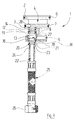
Figur 1- eine Explosionsansicht des zweiteiligen Bodens einer Sanitärarmatur sowie eines Wasserzufuhrschlauches mit den zugehörigen Befestigungselementen;
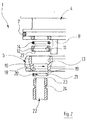
Figuren 2 bis 4- in Ausschnittvergrößerungen von
Figur 1 verschiedene Montageschritte bei der Befestigung des Wasserzufuhrschlauches am Boden.
- Figure 1
- an exploded view of the two-part bottom of a sanitary fitting and a water supply hose with the associated fasteners;
- Figures 2 to 4
- in enlarged sections of Figure 1 different assembly steps for attaching the water supply hose to the floor.
Die Hauptkomponenten der Explosionsansicht von Figur
1 sind ein aus zwei Teilen 4, 5 zusammensetzbarer Boden
1 einer sanitären Mischarmatur, wie dieser an und für
sich bekannt ist, sowie ein Wasserzufuhrschlauch 25,
der ohne Zuhilfenahme einer Lötung lösbar an dem Boden
1 befestigt werden soll.The main components of the exploded view of Figure
1 are a floor which can be assembled from two
Das obere Bodenteil 4 weist einen oberen flanschartigen
Bereich 2 und einen unteren flanschartigen Bereich 3
auf. In jeweils einer Umfangsnut dieser flanschartigen
Bereiche 2, 3 liegt eine O-Ring-Dichtung 6 bzw. 7, welche
bei der Anbringung des Bodens 1 in dem nur in Figur
4 teilweise dargestellte Armaturengehäuse 30 die Abdichtung
gegen dieses übernehmen.The
Das obere Bodenteil 4 weist zwei axiale Wasserdurchgangsbohrungen
28 auf, von denen in der Zeichnung nur eine
sichtbar ist. Diese Wasserdurchgangsbohrungen 28 erstrecken
sich bis zur oberen Stirnfläche des oberen Bodenteiles
4. Dort wird bei der fertig montierten Sanitärarmatur
eine Steuerkartusche 31 (Figur 4) so aufgesetzt, daß das
über die Bohrung 28 zufließende Wasser in die Steuerkartusche
gelangen kann.The
Das obere Bodenteil 4 läßt sich an dem unteren Bodenteil
5 mit Hilfe von Rastlaschen 8 befestigen, welche von
der Unterseite des oberen Bodenteiles 4 nach unten überstehen
und am unteren Bodenteil 5 so einrasten können,
daß die Bodenteile 4, 5 unter Bildung des Gesamtbodens 1
aneinander befestigt sind, wie dies in Figur 3 zum Ausdruck
gebracht ist.The
Auch das untere Bodenteil 5 weist, zu den Durchgangsbohrungen
28 des oberen Bodenteiles 4 fluchtend, zwei Durchgangsbohrungen
16 auf, die einen oberen im Durchmesser
erweiterten Bereich 13 und einen unteren im Durchmesser
kleineren Bereich 18 besitzt.The
Der Wasserzufuhrschlauch 25 ist an seinem dem Boden 1
der Sanitärarmatur zugewandten Ende mit einer starren
metallischen Steckhülse 22 versehen, die an ihrem freien
Ende mit einer Abschrägung 23 und in einem gewissen Abstand
von diesem Ende mit einer Umfangsringnut 24 versehen
ist. Am anderen Ende trägt der Wasserzufuhrschlauch 25
eine Verbindungsmutter 26, die in bekannter Weise dem
Anschluß des Wasserzufuhrschlauches 25 an der Hausleitung
dient.The
Zur wasserdichten, lösbaren Steckverbindung der Steckhülse
22 des Wasserzufuhrschlauches 25 werden zusätzlich
zu den bereits beschriebenen Hauptkomponenten ein O-Ring
14, ein Haltering 12 sowie ein mit einem Schlitz 21
versehener Sprengring 20 benötigt.For watertight, detachable plug connection of the
Die Montage der verschiedenen Elemente geschieht in folgender Weise:The various elements are assembled in in the following way:
Bereits werksseitig wird der Haltering 12 in den im
Durchmesser erweiterten Bereich 13 der Durchgangsbohrung
16 des unteren Bodenteiles 5 eingesetzt. Dieser im Durchmesser
erweiterte Bereich 13 besitzt eine solche Höhe,
daß oberhalb des Halteringes 12 in ihm der O-Ring 14
so weit Platz findet, daß er geringfügig übersteht.
Nun wird das obere Bodenteil 4, wie das der Figur 3
zu entnehmen ist, mit Hilfe der Rastlaschen 3 auf das
untere Bodenteil 5 aufgesteckt und an diesem befestigt.
Der O-Ring 14 wird dabei so weit komprimiert, daß der
Übergangsbereich zwischen den Durchgangsbohrungen 16
im unteren Bodenteil 5 und 28 im oberen Bodenteil 4
nach außen abgedichtet ist.The
Der untere Bereich 27 der Durchgangsbohrung des Halteringes
12 weist einen etwas größeren Durchmesser auf
als der nach unten benachbarte Bereich 18 kleineren
Durchmessers der Durchgangsbohrung 16 des unteren Bodenteiles
5. Der obere Bereich 11 dieser Durchgangsbohrung
dagegen weist denselben Durchmesser wie der untere Bereich
18 der Durchgangsbohrung 16 und die Durchgangsbohrung
28 im oberen Bodenteil 4 auf. Auf diese Weise entsteht
zwischen dem Haltering 12 und der Stufe der Durchgangsbohrung
16 des unteren Bodenteiles 5 ein Aufnahmeraum
40 für den zunächst sich noch außerhalb des Bodens 1
befindlichen Sprengring 20.The
Der fertigmontierte Boden 1 wird sodann werksseitig
in dem Armaturengehäuse 30 montiert. Der Sprengring
20 wird mit Hilfe seiner Schlitzung 21 aufgeweitet und
in die Umfangsnut 24 an der Steckhülse 22 des Wasserzufuhrschlauches
2 eingesetzt.The fully assembled
Außen- und Innendurchmesser des Sprengringes 20 sind dabei
folgendermaßen dimensioniert:The outer and inner diameters of the
In entspanntem Zustand, wie er in den Figuren 1, 2 und
3 dargestellt ist, weist der Sprengring 20 einen Außendurchmesser
auf, der etwa dem Durchmesser des unteren Bereiches
27 der Durchgangsbohrung des Halteringes 12 entspricht;
der Innendurchmesser im entspannten Zustand ist kleiner
als der Außendurchmesser der Steckhülse 22 des Wasserzufuhrschlauches
25. Die Tiefe der Nut 24 in der Steckhülse
22 ist dabei so groß, daß der Sprengring 20 bis auf
einen Außendurchmesser komprimiert werden kann, der
gleich dem Durchmesser des unteren Bereiches 18 der
Durchgangsbohrung 16 im unteren Bodenteil 5 ist.In a relaxed state, as shown in Figures 1, 2 and
3, the
Die soweit montierte Sanitärarmatur wird nunmehr zum Versand gebracht.The sanitary fitting installed so far is now the Shipping brought.
Vor Ort wird die beschriebene Sanitärarmatur vom Sanitärinstallateur
an der gewünschten Stelle, z.B. an einem
Waschtisch, befestigt. Zum ihrem Anschluß an die Hausleitung
geht er folgendermaßen vor: Die Steckhülse 22 mit
dem eingesetzten Sprengring 20 wird von unten her gegen
die Durchgangsbohrung 16 des unteren Bodenteiles 5 geführt.
Aufgrund einer Abschrägung 19 im Bereich der unteren
Mündung dieser Durchgangsbohrung 16 wird der Sprengring
20 innerhalb der Nut 24 der Steckhülse 22 so weit komprimiert,
bis er sein Außendurchmesser den Durchmesser des
unteren Bereiches 18 der Durchgangsbohrung 16 erreicht
hat. Nunmehr läßt sich die Steckhülse 22 mit dem Sprengring
20 durch diesen Bereich 18 der Durchgangsbohrung 16
hindurchschieben, bis der Sprengring 20 in dem Aufnahmeraum
40 angekommen ist. Dort kann er, wie der Figur 4 zu
entnehmen ist, auffedern und verriegelt die axiale Bewegung
der Steckhülse 22 innerhalb der Durchgangsbohrung 16 des
unteren Bodenteiles 5.The sanitary fitting described is installed on site by the sanitary fitter
at the desired location, e.g. on one
Vanity, attached. For your connection to the house management
he does the following: The
Abschließend wird der Wasserzufuhrschlauch 25 mit Hilfe der
Überwurfmutter 26 an der Hausleitung angeschlossen. Da sich
die Steckhülse 22 nach dem Auffedern im Aufnahmeraum
verdrehen kann, braucht der Installateur beim Aufschrauben
der Überwurfmutter 26 den Wasserzufuhrschlauch 25 nicht
festzuhalten; vielemehr kann eine Verdrehung dieses
Wasserzufuhrschlauches 25 zugelassen werden. Die Sanitärarmatur
ist nunmehr betriebsbereit.Finally, the
Claims (4)
wobei
dadurch gekennzeichnet, daß
in which
characterized in that
Applications Claiming Priority (2)
| Application Number | Priority Date | Filing Date | Title |
|---|---|---|---|
| DE19911574 | 1999-03-16 | ||
| DE19911574A DE19911574C2 (en) | 1999-03-16 | 1999-03-16 | plumbing fixture |
Publications (2)
| Publication Number | Publication Date |
|---|---|
| EP1036973A1 true EP1036973A1 (en) | 2000-09-20 |
| EP1036973B1 EP1036973B1 (en) | 2002-10-23 |
Family
ID=7901091
Family Applications (1)
| Application Number | Title | Priority Date | Filing Date |
|---|---|---|---|
| EP00102483A Revoked EP1036973B1 (en) | 1999-03-16 | 2000-02-05 | Sanitary fitting |
Country Status (5)
| Country | Link |
|---|---|
| EP (1) | EP1036973B1 (en) |
| AT (1) | ATE226700T1 (en) |
| DE (2) | DE19911574C2 (en) |
| ES (1) | ES2182741T3 (en) |
| PL (1) | PL195406B1 (en) |
Cited By (4)
| Publication number | Priority date | Publication date | Assignee | Title |
|---|---|---|---|---|
| FR2858374A1 (en) * | 2003-07-29 | 2005-02-04 | Delphi Tech Inc | ELECTROVALVE, METHOD FOR ASSEMBLING A SOLENOID ON SAID ELECTROVALVE, AND METHOD FOR DISASSEMBLING SOLENOID OF SAID ELECTROVALVE |
| WO2008120252A1 (en) * | 2007-03-30 | 2008-10-09 | Crs S.P.A. | Tap |
| WO2010062331A1 (en) * | 2008-10-28 | 2010-06-03 | Kohler Co. | Sprayer seating assembly |
| US9657874B2 (en) | 2014-04-25 | 2017-05-23 | Kohler Co. | Plumbing fitting adapter |
Families Citing this family (3)
| Publication number | Priority date | Publication date | Assignee | Title |
|---|---|---|---|---|
| DE10234206A1 (en) * | 2002-07-19 | 2004-01-29 | Hansgrohe Ag | Plug connection for sanitary fittings |
| DE10311801A1 (en) * | 2003-03-12 | 2004-09-23 | Hansgrohe Ag | Device for attaching a line |
| DE102019104774A1 (en) * | 2019-02-26 | 2020-08-27 | Grohe Ag | Securing element for securing lines in the sanitary area |
Citations (3)
| Publication number | Priority date | Publication date | Assignee | Title |
|---|---|---|---|---|
| US4645245A (en) * | 1985-10-07 | 1987-02-24 | General Motors Corporation | Quick connect tube coupling |
| EP0681127A1 (en) * | 1994-05-05 | 1995-11-08 | Friedrich Grohe Aktiengesellschaft | Water fitting |
| US5685341A (en) * | 1996-09-10 | 1997-11-11 | Amerikam, Inc. | Water faucet with quick-connect socket |
Family Cites Families (4)
| Publication number | Priority date | Publication date | Assignee | Title |
|---|---|---|---|---|
| DE3405229A1 (en) * | 1984-02-14 | 1985-09-05 | Hermann Ing.(grad.) 7210 Rottweil Breucha | Connecting piece for hose lines |
| DE19512721C1 (en) * | 1995-04-05 | 1996-10-10 | Cgs Analysen Mess Und Regeltec | Plug-in coupling, in particular for a heated hose line |
| DE29509041U1 (en) * | 1995-06-01 | 1995-08-24 | Kemper Gmbh & Co Metallwerke G | Device for connecting pipes or the like. tubular fitting parts with a fitting for fluid media |
| EP0898109B1 (en) * | 1997-08-19 | 2003-05-21 | Johannes Schäfer vormals Stettiner Schraubenwerke GmbH & Co. KG | Plug coupling for pipes |
-
1999
- 1999-03-16 DE DE19911574A patent/DE19911574C2/en not_active Expired - Fee Related
-
2000
- 2000-02-05 DE DE50000666T patent/DE50000666D1/en not_active Revoked
- 2000-02-05 ES ES00102483T patent/ES2182741T3/en not_active Expired - Lifetime
- 2000-02-05 AT AT00102483T patent/ATE226700T1/en not_active IP Right Cessation
- 2000-02-05 EP EP00102483A patent/EP1036973B1/en not_active Revoked
- 2000-03-09 PL PL338913A patent/PL195406B1/en not_active IP Right Cessation
Patent Citations (4)
| Publication number | Priority date | Publication date | Assignee | Title |
|---|---|---|---|---|
| US4645245A (en) * | 1985-10-07 | 1987-02-24 | General Motors Corporation | Quick connect tube coupling |
| EP0681127A1 (en) * | 1994-05-05 | 1995-11-08 | Friedrich Grohe Aktiengesellschaft | Water fitting |
| EP0681127B1 (en) | 1994-05-05 | 1998-07-15 | Friedrich Grohe Aktiengesellschaft | Water fitting |
| US5685341A (en) * | 1996-09-10 | 1997-11-11 | Amerikam, Inc. | Water faucet with quick-connect socket |
Cited By (7)
| Publication number | Priority date | Publication date | Assignee | Title |
|---|---|---|---|---|
| FR2858374A1 (en) * | 2003-07-29 | 2005-02-04 | Delphi Tech Inc | ELECTROVALVE, METHOD FOR ASSEMBLING A SOLENOID ON SAID ELECTROVALVE, AND METHOD FOR DISASSEMBLING SOLENOID OF SAID ELECTROVALVE |
| WO2005015582A1 (en) * | 2003-07-29 | 2005-02-17 | Delphi Technologies, Inc. | Electromagnetic valve, method for attaching a solenoid to said electromagnetic valve, and method for detaching the solenoid from this electromagnetic valve |
| US7618018B2 (en) | 2003-07-29 | 2009-11-17 | Delphi Technologies, Inc. | Assembly comprising electrically operated valve, and process for assembling a solenoid on a housing of the valve |
| WO2008120252A1 (en) * | 2007-03-30 | 2008-10-09 | Crs S.P.A. | Tap |
| WO2010062331A1 (en) * | 2008-10-28 | 2010-06-03 | Kohler Co. | Sprayer seating assembly |
| US8863769B2 (en) | 2008-10-28 | 2014-10-21 | Kohler Co. | Sprayer seating assembly |
| US9657874B2 (en) | 2014-04-25 | 2017-05-23 | Kohler Co. | Plumbing fitting adapter |
Also Published As
| Publication number | Publication date |
|---|---|
| ATE226700T1 (en) | 2002-11-15 |
| DE50000666D1 (en) | 2002-11-28 |
| ES2182741T3 (en) | 2003-03-16 |
| PL195406B1 (en) | 2007-09-28 |
| DE19911574A1 (en) | 2000-11-02 |
| DE19911574C2 (en) | 2003-05-08 |
| PL338913A1 (en) | 2000-09-25 |
| EP1036973B1 (en) | 2002-10-23 |
Similar Documents
| Publication | Publication Date | Title |
|---|---|---|
| EP1382757B1 (en) | Sanitary installation unit | |
| DE102011085346B4 (en) | plumbing fixture | |
| DE102004040084B4 (en) | Sanitary concealed fitting | |
| EP1036973B1 (en) | Sanitary fitting | |
| DE2527132C3 (en) | Connection device for a radiator | |
| EP1724523A1 (en) | Luminaire, in particular for cupboard, shelf or the like | |
| EP0217321A2 (en) | Shut-off valve | |
| EP1022500B1 (en) | Sanitary valve, especially for wash basins | |
| EP2853643B1 (en) | Connecting body system for a concealed mounted sanitary fixture | |
| DE102013205250A1 (en) | Pipe connection adapter and sanitary fitting | |
| DE3924795C2 (en) | Fluid connection device | |
| DE952307C (en) | Automatic pipe or hose coupling | |
| DE10057229B4 (en) | Wall connection fitting for fittings | |
| DE102004061225B3 (en) | Sanitary water outlet fitting with at least one water outlet pipe | |
| EP0780523B1 (en) | Mixing valve with inclined mounted supply conduit | |
| EP0669504A1 (en) | Hydraulic coupling | |
| EP1136629B1 (en) | Sanitary fitting for flushing | |
| EP0762037A1 (en) | Threaded tube connector | |
| EP0760444B1 (en) | Sanitary armature, particularly thermostatic valve | |
| EP1006241B1 (en) | Sanitary fitting with noise suppressor | |
| DE2036708A1 (en) | Protective device for pipe fitting | |
| WO2023174540A1 (en) | Adapter for a drainage device | |
| DE19961418A1 (en) | Installation set with detachable bell adapter | |
| DE202022101408U1 (en) | Drainage device with an adjustable support for a drain cover | |
| WO2023174541A1 (en) | Drainage device with an adjustable carrier for a drain cover |
Legal Events
| Date | Code | Title | Description |
|---|---|---|---|
| PUAI | Public reference made under article 153(3) epc to a published international application that has entered the european phase |
Free format text: ORIGINAL CODE: 0009012 |
|
| AK | Designated contracting states |
Kind code of ref document: A1 Designated state(s): AT BE CH CY DE DK ES FI FR GB GR IE IT LI LU MC NL PT SE |
|
| AX | Request for extension of the european patent |
Free format text: AL;LT;LV;MK;RO;SI |
|
| 17P | Request for examination filed |
Effective date: 20001230 |
|
| AKX | Designation fees paid |
Free format text: AT BE CH CY DE DK ES FI FR GB GR IE IT LI LU MC NL PT SE |
|
| GRAG | Despatch of communication of intention to grant |
Free format text: ORIGINAL CODE: EPIDOS AGRA |
|
| 17Q | First examination report despatched |
Effective date: 20020328 |
|
| GRAG | Despatch of communication of intention to grant |
Free format text: ORIGINAL CODE: EPIDOS AGRA |
|
| GRAH | Despatch of communication of intention to grant a patent |
Free format text: ORIGINAL CODE: EPIDOS IGRA |
|
| GRAH | Despatch of communication of intention to grant a patent |
Free format text: ORIGINAL CODE: EPIDOS IGRA |
|
| GRAA | (expected) grant |
Free format text: ORIGINAL CODE: 0009210 |
|
| AK | Designated contracting states |
Kind code of ref document: B1 Designated state(s): AT BE CH CY DE DK ES FI FR GB GR IE IT LI LU MC NL PT SE |
|
| PG25 | Lapsed in a contracting state [announced via postgrant information from national office to epo] |
Ref country code: FI Free format text: LAPSE BECAUSE OF FAILURE TO SUBMIT A TRANSLATION OF THE DESCRIPTION OR TO PAY THE FEE WITHIN THE PRESCRIBED TIME-LIMIT Effective date: 20021023 Ref country code: GB Free format text: LAPSE BECAUSE OF FAILURE TO SUBMIT A TRANSLATION OF THE DESCRIPTION OR TO PAY THE FEE WITHIN THE PRESCRIBED TIME-LIMIT Effective date: 20021023 Ref country code: GR Free format text: LAPSE BECAUSE OF FAILURE TO SUBMIT A TRANSLATION OF THE DESCRIPTION OR TO PAY THE FEE WITHIN THE PRESCRIBED TIME-LIMIT Effective date: 20021023 Ref country code: IE Free format text: LAPSE BECAUSE OF FAILURE TO SUBMIT A TRANSLATION OF THE DESCRIPTION OR TO PAY THE FEE WITHIN THE PRESCRIBED TIME-LIMIT Effective date: 20021023 |
|
| REF | Corresponds to: |
Ref document number: 226700 Country of ref document: AT Date of ref document: 20021115 Kind code of ref document: T |
|
| REG | Reference to a national code |
Ref country code: GB Ref legal event code: FG4D Free format text: NOT ENGLISH |
|
| REG | Reference to a national code |
Ref country code: CH Ref legal event code: EP |
|
| REG | Reference to a national code |
Ref country code: IE Ref legal event code: FG4D Free format text: GERMAN |
|
| REF | Corresponds to: |
Ref document number: 50000666 Country of ref document: DE Date of ref document: 20021128 |
|
| REG | Reference to a national code |
Ref country code: CH Ref legal event code: NV Representative=s name: FREI PATENTANWALTSBUERO |
|
| PG25 | Lapsed in a contracting state [announced via postgrant information from national office to epo] |
Ref country code: SE Free format text: LAPSE BECAUSE OF FAILURE TO SUBMIT A TRANSLATION OF THE DESCRIPTION OR TO PAY THE FEE WITHIN THE PRESCRIBED TIME-LIMIT Effective date: 20030123 Ref country code: PT Free format text: LAPSE BECAUSE OF FAILURE TO SUBMIT A TRANSLATION OF THE DESCRIPTION OR TO PAY THE FEE WITHIN THE PRESCRIBED TIME-LIMIT Effective date: 20030123 Ref country code: DK Free format text: LAPSE BECAUSE OF FAILURE TO SUBMIT A TRANSLATION OF THE DESCRIPTION OR TO PAY THE FEE WITHIN THE PRESCRIBED TIME-LIMIT Effective date: 20030123 |
|
| PG25 | Lapsed in a contracting state [announced via postgrant information from national office to epo] |
Ref country code: CY Free format text: LAPSE BECAUSE OF FAILURE TO SUBMIT A TRANSLATION OF THE DESCRIPTION OR TO PAY THE FEE WITHIN THE PRESCRIBED TIME-LIMIT Effective date: 20030205 Ref country code: LU Free format text: LAPSE BECAUSE OF NON-PAYMENT OF DUE FEES Effective date: 20030205 |
|
| PG25 | Lapsed in a contracting state [announced via postgrant information from national office to epo] |
Ref country code: MC Free format text: LAPSE BECAUSE OF NON-PAYMENT OF DUE FEES Effective date: 20030228 |
|
| REG | Reference to a national code |
Ref country code: ES Ref legal event code: FG2A Ref document number: 2182741 Country of ref document: ES Kind code of ref document: T3 |
|
| GBV | Gb: ep patent (uk) treated as always having been void in accordance with gb section 77(7)/1977 [no translation filed] |
Effective date: 20021023 |
|
| ET | Fr: translation filed | ||
| REG | Reference to a national code |
Ref country code: IE Ref legal event code: FD4D Ref document number: 1036973E Country of ref document: IE |
|
| PLBI | Opposition filed |
Free format text: ORIGINAL CODE: 0009260 |
|
| PLAX | Notice of opposition and request to file observation + time limit sent |
Free format text: ORIGINAL CODE: EPIDOSNOBS2 |
|
| 26 | Opposition filed |
Opponent name: FRIEDRICH GROHE AG & CO. KG Effective date: 20030710 |
|
| NLR1 | Nl: opposition has been filed with the epo |
Opponent name: FRIEDRICH GROHE AG & CO. KG |
|
| PLAB | Opposition data, opponent's data or that of the opponent's representative modified |
Free format text: ORIGINAL CODE: 0009299OPPO |
|
| PLBB | Reply of patent proprietor to notice(s) of opposition received |
Free format text: ORIGINAL CODE: EPIDOSNOBS3 |
|
| R26 | Opposition filed (corrected) |
Opponent name: GROHE WATER TECHNOLOGY AG & CO. KG Effective date: 20030710 |
|
| PLAY | Examination report in opposition despatched + time limit |
Free format text: ORIGINAL CODE: EPIDOSNORE2 |
|
| NLR1 | Nl: opposition has been filed with the epo |
Opponent name: GROHE WATER TECHNOLOGY AG & CO. KG |
|
| PLBC | Reply to examination report in opposition received |
Free format text: ORIGINAL CODE: EPIDOSNORE3 |
|
| PLAY | Examination report in opposition despatched + time limit |
Free format text: ORIGINAL CODE: EPIDOSNORE2 |
|
| PLBC | Reply to examination report in opposition received |
Free format text: ORIGINAL CODE: EPIDOSNORE3 |
|
| PLAB | Opposition data, opponent's data or that of the opponent's representative modified |
Free format text: ORIGINAL CODE: 0009299OPPO |
|
| R26 | Opposition filed (corrected) |
Opponent name: GROHE WATER TECHNOLOGY AG & CO. KG Effective date: 20030710 |
|
| PLCK | Communication despatched that opposition was rejected |
Free format text: ORIGINAL CODE: EPIDOSNREJ1 |
|
| NLR1 | Nl: opposition has been filed with the epo |
Opponent name: GROHE WATER TECHNOLOGY AG & CO. KG |
|
| APBP | Date of receipt of notice of appeal recorded |
Free format text: ORIGINAL CODE: EPIDOSNNOA2O |
|
| APAH | Appeal reference modified |
Free format text: ORIGINAL CODE: EPIDOSCREFNO |
|
| APBQ | Date of receipt of statement of grounds of appeal recorded |
Free format text: ORIGINAL CODE: EPIDOSNNOA3O |
|
| APAH | Appeal reference modified |
Free format text: ORIGINAL CODE: EPIDOSCREFNO |
|
| PGFP | Annual fee paid to national office [announced via postgrant information from national office to epo] |
Ref country code: CH Payment date: 20080229 Year of fee payment: 9 Ref country code: ES Payment date: 20080215 Year of fee payment: 9 |
|
| PGFP | Annual fee paid to national office [announced via postgrant information from national office to epo] |
Ref country code: IT Payment date: 20080228 Year of fee payment: 9 Ref country code: NL Payment date: 20080229 Year of fee payment: 9 |
|
| PGFP | Annual fee paid to national office [announced via postgrant information from national office to epo] |
Ref country code: AT Payment date: 20080229 Year of fee payment: 9 |
|
| PGFP | Annual fee paid to national office [announced via postgrant information from national office to epo] |
Ref country code: DE Payment date: 20080409 Year of fee payment: 9 Ref country code: FR Payment date: 20080229 Year of fee payment: 9 |
|
| PGFP | Annual fee paid to national office [announced via postgrant information from national office to epo] |
Ref country code: BE Payment date: 20080312 Year of fee payment: 9 |
|
| APBU | Appeal procedure closed |
Free format text: ORIGINAL CODE: EPIDOSNNOA9O |
|
| RDAF | Communication despatched that patent is revoked |
Free format text: ORIGINAL CODE: EPIDOSNREV1 |
|
| RDAG | Patent revoked |
Free format text: ORIGINAL CODE: 0009271 |
|
| STAA | Information on the status of an ep patent application or granted ep patent |
Free format text: STATUS: PATENT REVOKED |
|
| REG | Reference to a national code |
Ref country code: CH Ref legal event code: PL |
|
| 27W | Patent revoked |
Effective date: 20090109 |
|
| NLR2 | Nl: decision of opposition |
Effective date: 20090109 |
|
| PLAB | Opposition data, opponent's data or that of the opponent's representative modified |
Free format text: ORIGINAL CODE: 0009299OPPO |
|
| R26 | Opposition filed (corrected) |
Opponent name: GROHE WATER TECHNOLOGY AG & CO. KG Effective date: 20030710 |