EP1036959B1 - Dispositif de commande impulsionnelle de passage de vitesse - Google Patents
Dispositif de commande impulsionnelle de passage de vitesse Download PDFInfo
- Publication number
- EP1036959B1 EP1036959B1 EP20000400267 EP00400267A EP1036959B1 EP 1036959 B1 EP1036959 B1 EP 1036959B1 EP 20000400267 EP20000400267 EP 20000400267 EP 00400267 A EP00400267 A EP 00400267A EP 1036959 B1 EP1036959 B1 EP 1036959B1
- Authority
- EP
- European Patent Office
- Prior art keywords
- lever
- slide
- positions
- plate
- translation
- Prior art date
- Legal status (The legal status is an assumption and is not a legal conclusion. Google has not performed a legal analysis and makes no representation as to the accuracy of the status listed.)
- Expired - Lifetime
Links
- 230000005540 biological transmission Effects 0.000 title description 3
- 230000005032 impulse control Effects 0.000 claims description 14
- 230000004907 flux Effects 0.000 claims description 7
- 108091008695 photoreceptors Proteins 0.000 description 25
- 230000008901 benefit Effects 0.000 description 6
- 230000000694 effects Effects 0.000 description 3
- 240000008042 Zea mays Species 0.000 description 2
- 239000003795 chemical substances by application Substances 0.000 description 2
- 239000006185 dispersion Substances 0.000 description 2
- 230000005355 Hall effect Effects 0.000 description 1
- 238000006073 displacement reaction Methods 0.000 description 1
- 239000000428 dust Substances 0.000 description 1
- -1 humidity Substances 0.000 description 1
- 238000002513 implantation Methods 0.000 description 1
- 108091008702 infrared receptors Proteins 0.000 description 1
- 238000009434 installation Methods 0.000 description 1
- 238000004519 manufacturing process Methods 0.000 description 1
- 230000000873 masking effect Effects 0.000 description 1
- 230000007935 neutral effect Effects 0.000 description 1
- 230000005693 optoelectronics Effects 0.000 description 1
- 108020003175 receptors Proteins 0.000 description 1
- XLYOFNOQVPJJNP-UHFFFAOYSA-N water Substances O XLYOFNOQVPJJNP-UHFFFAOYSA-N 0.000 description 1
Images

Classifications
-
- F—MECHANICAL ENGINEERING; LIGHTING; HEATING; WEAPONS; BLASTING
- F16—ENGINEERING ELEMENTS AND UNITS; GENERAL MEASURES FOR PRODUCING AND MAINTAINING EFFECTIVE FUNCTIONING OF MACHINES OR INSTALLATIONS; THERMAL INSULATION IN GENERAL
- F16H—GEARING
- F16H59/00—Control inputs to control units of change-speed- or reversing-gearings for conveying rotary motion
- F16H59/02—Selector apparatus
- F16H59/0204—Selector apparatus for automatic transmissions with means for range selection and manual shifting, e.g. range selector with tiptronic
-
- F—MECHANICAL ENGINEERING; LIGHTING; HEATING; WEAPONS; BLASTING
- F16—ENGINEERING ELEMENTS AND UNITS; GENERAL MEASURES FOR PRODUCING AND MAINTAINING EFFECTIVE FUNCTIONING OF MACHINES OR INSTALLATIONS; THERMAL INSULATION IN GENERAL
- F16H—GEARING
- F16H59/00—Control inputs to control units of change-speed- or reversing-gearings for conveying rotary motion
- F16H59/02—Selector apparatus
- F16H2059/0239—Up- and down-shift or range or mode selection by repeated movement
Definitions
- the invention relates to a control device gear shift impulse, especially for a motor vehicle, this device comprising a control lever movable in directions perpendiculars between a first position of automatic control, a second position of manual control and two control positions pulse, controlled switching means by the lever being provided to generate signals electric in said lever positions, these signals being applied to processing means the information to control the change of gears.
- Return means are associated with the lever to move it to its second position from of its two impulse control positions.
- Such a device combines the advantages of a automatic gearbox and a gearbox manual gears, the driver of the vehicle benefiting from these two possibilities and going from one to the other as he wishes.
- EP-A-846 897 which corresponds to the closest state of the art, has already been proposed, from the same applicant, to use micro switches to two conduction states actuated by pushers moved by the lever, to produce signals of shift control.
- This known device is cost-effective, compared to other solutions in which we use Hall effect sensors or the like, but the association from microswitches to actuators does not allow you to control the dispersion of dimensions, which leads to inaccuracies in the order impulse speeds.
- the object of the invention is in particular to avoid disadvantages mentioned above in a simple, effective and economic to this problem while improving the reliability of the control.
- a system for impulse shift control comprising a control lever movable in perpendicular directions between at least one first automatic control position, one second manual control position and two impulse control positions, means of lever-controlled switching to produce electrical signals in said positions of the lever, and means for returning the lever to its second position from its two positions of impulse control, characterized in that said switching means comprise a source light associated with two photoreceptors, and in this that the lever is secured in its second position with screen means, which include a plate guided in translation on a slide parallel to the direction of movement of the lever between its first and its second position, the slide being itself guided in translation parallel to the direction of movement of the lever between its two positions impulse control, the light source and the the aforementioned photoreceptors being arranged on the side and other side of the wafer and its trajectory in translation, the lever being secured to the means forming a screen by moving its first position and separable from the screen means by moving from its second position in its first position.
- the lever is automatically separated from the means forming screen when moved from its control position manual to its automatic control position, and more likely then to accidentally move the screen means when in position automatic control, which avoids incidents of operation and improves reliability and security.
- the device according to the invention also has the advantage of using switching means without optoelectronic type contacts, which generate control signals as a result of the cut-off or reestablishing a light beam.
- This device includes few moving parts it is little subject to wear, it is easy to assemble and economical (the number of parts is reduced and the components are cheap) and it's practically insensitive to the environment. The dispersions of ratings in this device are much lower that in the prior art and the precision of the order is bigger.
- the light source is a light emitting diode emitting in the infrared and the photoreceptors are phototransistors operating in the infrared.
- Such a transmitter and the two associated receivers are particularly inexpensive.
- part of the lever comes to apply on the plate in the second lever position and move it in translation on the slide against the action of a means of reminder, this part of the lever engaging simultaneously in a slide notch and there remaining maintained by any appropriate means, by for example by friction, by snap-fastening, etc.
- the lever thus being integral with the slide, can move it between two positions opposite corresponding to the two control positions impulse, the plate carried by the slide being moved with the latter to unmask a photoreceptor by exposing it to the emitted light flux by the source, while leaving the other masked photoreceptor, and vice versa when the lever moves the slide in the opposite direction.
- the slide is associated with means forming a hard point, such as a ball or a pusher loaded by a spring and engaging in a notch of the slide when it is in a position intermediate located between the two positions of impulse speed control.
- the plate, the slide, their means of recall, the light source and the two associated photoreceptors, with means supply and connection of the source and photoreceptors are mounted in a housing which is itself attached to the lever lever mounting housing ordered.
- This case and the components it contains constitute a subset that can be prepared independently and then just fix it on the control lever mounting case by connecting to an appropriate electrical circuit, which significantly simplifies the assembly and installation of a device according to the invention.
- this subset forms a standard module that we can mount on a pre-existing speed control.
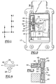
- the gearshift control device shown in the accompanying drawings comprises a lever control which is movable in a grid of speeds between a number of positions, such than those shown in Figure 1, including the positions P (parking), R (reverse), N (neutral) and D (drive or route), which are the classic control positions of a box of automatic gears, with an additional M position (manual control) located at position D and placed between two positions + and - (switch to higher speed and shift to speed lower, respectively).
- the device according to the invention comprises a housing 10 for fixing to a rigid part of the vehicle, this casing comprising means (not shown) mounting a control lever 12 in rotation around two perpendicular axes substantially contained in the drawing plane in Figure 2, this double articulation allowing move the lever successively to the positions P, R, N, D by rotation around a first axis, then in position M by rotation around a second axis, then in positions + and - by rotation around the first axis.
- the lever 12 comprises a cylindrical rod 14 extending outside the casing 10 and intended to be handled by the driver of the vehicle, and connected by a U-shaped piece 16 forming a clevis to the axes of articulation mentioned above.
- One 18 of the two branches part 16 is intended to cooperate with a slide 20 which is guided in translation in a housing 22 fixed to a side wall of the casing 10, the slide 20 being movable in the direction defined by the above positions + and -, this direction being here parallel to that defined by positions P, R, N and D.
- a notch 24 is formed in the middle part of the slide 20 for receive the edge of the branch 18 of the part 16, whose thickness is substantially equal to the corresponding dimension of the notch 24 of such so that the branch 18 engaged in the notch 24 y remains held by friction.
- Other ways could be used for this purpose, for example snap-in or billing means, or means magnetic.
- a longitudinal slot 26 which is perpendicular to the notch 24 and which opens into the latter, for guiding in translation of a plate 28 in a direction parallel to that defined by positions M and D, plate 28 being sought in the direction of branch 18 of lever by a return spring 30 mounted in a cylindrical housing formed in a side wall of the box 22.
- the plate 28 On the side of the branch 18 of the lever 12, the plate 28 includes a middle branch 32 extending inside the notch 24 and two lateral branches 34 received in housings blinds of the slide 20 and making it possible to define a position, shown in Figure 2, of the plate 28 when its lateral branches 34 are engaged completely in the abovementioned blind dwellings of the slide.
- the plate 28 unmasks two photoreceptors 36 which are then exposed to luminous flux emitted by a light source 38.
- this source of light 38 is located above the drawing plane.
- the plate 28 is interposed between the source 38 and the photoreceptors 36 it is displaced perpendicular to the plane of the drawing (in the slot 26 of slide 20) when the lever is brought from the position D in position M, and it is moved in translation in the drawing plane in the direction indicated by the arrows to unmask either of the photoreceptors 36 when the lever 12 is moved in one or other of the impulse control positions + and -.
- Photoreceptors 36 and light source 38 are mounted on a fixed printed circuit board on a side wall of the housing 22 and are connected to power supply means as well as control means and means of the signals emitted by the photoreceptors 36.
- the light source 38 is a light emitting diode emitting in infrared
- photoreceptors 36 are phototransistors operating in the infrared.
- lever 12 of the device according to the invention is found in the position D and its branch 18 is moved away from the slide 20 and the plate 28.
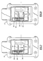
- lever 12 To be brought into position M from position D, lever 12 is moved in the direction indicated by the arrow F in FIG. 2, which has for effect of engaging its branch 18 in the slot 24 of the slide 20 and push the plate 28 to against the action of its return spring 30, the edge of the branch 18 of the lever coming to bear on the central tooth 32 of the insert, as shown in Figures 6 and 7, the plate 28 being thus moved by translation in the slot 26 of the slide 20, in the direction indicated by arrow F.
- the plate 28 masks the two photoreceptors 36 which no longer receive the luminous flux emitted by the source 38.
- lever 12 can be brought into one either of the + and - positions, by displacement by example in the direction indicated by the arrow in the figure 7 to be brought into position - shown in figure 8, which has the effect of moving the slide 20 in translation in the housing 22 in the same direction as lever 12, and to move the wafer 28 which unmasks one of the photoreceptors 36, the other photoreceptor remaining masked.
- Return means such as springs helical 40, are associated with the slide 20 in the housing 22 to constantly urge it towards its intermediate position shown in Figures 2 and 7 from either of its positions of impulse speed control.
- These springs 40 take for example support by one end on a wall of the housing 22, their other end being received in a blind cylindrical housing of the slide 20.
- Hard point means are associated with slide 20 and include for example a ball or a pusher 42 biased by a spring 44 towards a notch 46 of the slide.
- Pusher 42 and its spring 44 are housed and guided in a well cylindrical of the housing 22 and are oriented perpendicular to the direction of translation of the slide 20.
- the intermediate position of the slide which corresponds to position M of the lever 12
- the end of the pusher 42 is engaged in the notch 46 of the slide.
- the notch 46 of the slide has the shape of a V, the two branches of which constitute inclined ramps cooperating with the end of the pusher 42.
- the impulse control signals for passage of speed are provided by photoreceptors 36 when they are in turn unmasked by the plate 28.
- This allows the race to be precisely fixed necessary for the transmission of a pass signal from speed and make it substantially independent of manufacturing and mounting tolerances, since the photoreceptors 36 are always masked and unmasked for the same positions of the plate 28.
Landscapes
- Engineering & Computer Science (AREA)
- General Engineering & Computer Science (AREA)
- Mechanical Engineering (AREA)
- Arrangement Or Mounting Of Control Devices For Change-Speed Gearing (AREA)
- Control Of Transmission Device (AREA)
- Mechanical Control Devices (AREA)
Description
et les photorécepteurs sont des phototransistors fonctionnant dans l'infrarouge.
- la figure 1 représente schématiquement une grille de vitesses d'un dispositif de commande selon l'invention ;
- la figure 2 est une vue schématique en coupe transversale de ce dispositif, le levier étant dans la position D ;
- la figure 3 est une vue schématique partielle en coupe selon la ligne III-III de la figure 2 ;
- la figure 4 représente schématiquement l'implantation de la source lumineuse et des photorécepteurs ;
- la figure 5 est une vue schématique partielle en perspective du dispositif de commande selon l'invention, dans la position D ;
- la figure 6 est une vue schématique partielle en perspective de ce dispositif dans la position M ;
- la figure 7 est une vue en coupe transversale, semblable à la figure 2, mais représentant le dispositif dans la position M ;
- la figure 8 est une vue semblable à la figure 7, mais représentant le dispositif dans une position de commande impulsionnelle de passage à la vitesse inférieure.
- position D = 1 - 1
- position M = 0 - 0
- position + = 0 - 1
- position - = 1 - 0
- un très faible encombrement,
- une usure plus faible (nombre de pièces mobiles réduit),
- un sous-ensemble de commande formé par le boítier, le coulisseau, la plaquette, la source lumineuse, les photorécepteurs et un circuit imprimé associé,
- une possibilité de pose des composants en automatique,
- une insensibilité aux champs magnétiques et aux agents environnants,
- un seul coulisseau avec un rappel permettant de compenser le poids du levier, et un seul système de point dur,
- un prix de revient plus faible.
Claims (8)
- Dispositif de commande impulsionnelle de passage de vitesse, comprenant un levier de commande (12) déplaçable dans des directions perpendiculaires entre au moins une première position (D) de commande automatique, une deuxième position (M) de commande manuelle et deux positions de commande impulsionnelle, des moyens de commutation commandés par le levier (12) pour produire des signaux électriques dans lesdites positions du levier, lesdits moyens de commutation comprenant deux commutateurs de signal (44) et des moyens (30) de commutation de signal déplaçables par le levier (16) entre une première position où ils permettent la réception par les deux commutateurs de signal, une deuxième position où ils empêchent la réception de ce flux par les deux commutateurs de signal et deux autres positions où ils permettent la réception du flux par un commutateur de signal et interdisent sa réception par l'autre commutateur de signal, et des moyens de rappel du levier dans sa deuxième position à partir de ses deux positions de commande impulsionnelle, caractérisé en ce que lesdits moyens de commutation comprennent une source lumineuse (38) associée à deux photorécepteurs (36) et en ce que le levier (12) est solidarisé dans sa deuxième position (M) avec des moyens formant écran qui comprennent une plaquette (28) guidée en translation sur un coulisseau (20) parallèlement à la direction de déplacement du levier entre sa première position (D) et sa deuxième position (M), le coulisseau étant lui-même guidé en translation parallèlement à la direction de déplacement du levier entre ses deux positions (+, -) de commande impulsionnelle, ladite source lumineuse (38) et les photorécepteurs (36) étant agencés de part et d'autre de la plaquette (28) et de sa trajectoire en translation, le levier (12) étant solidarisable avec les moyens (20,28) formant écran par déplacement de sa première position (D) dans sa deuxième position (M) et désolidarisable des moyens (20,28) formant écran par déplacement de sa deuxième position (M) dans sa première position (D).
- Dispositif selon la revendication 1, caractérisé en ce que la source lumineuse (38) est une diode électroluminescente émettant dans l'infrarouge, et les photorécepteurs (36) sont des phototransistors fonctionnant dans l'infrarouge.
- Dispositif selon la revendication 1 ou 2, caractérisé en ce qu'une partie (18) du levier (12) vient s'appliquer sur la plaquette (28) dans la deuxième position (M) du levier et la déplace en translation sur le coulisseau à l'encontre de l'action d'un moyen de rappel (30), cette partie (18) du levier étant alors engagée dans une encoche (24) du coulisseau et y restant maintenue, par exemple par friction.
- Dispositif selon la revendication 1, 2 ou 3 caractérisé en ce que le coulisseau (20) est associé à des moyens de rappel (40) le sollicitant vers une position intermédiaire située entre les deux positions de commande impulsionnelle, ces moyens de rappel comprenant deux ressorts agissant sur les extrémités du coulisseau (20) dans des directions opposées.
- Dispositif selon la revendication 4, caractérisé en ce que les moyens (40) de rappel du coulisseau dans sa position intermédiaire constituent les moyens de rappel du levier (12) dans sa deuxième position (M), l'un de ces moyens de rappel étant dimensionné pour supporter le poids du levier (12) dans cette deuxième position.
- Dispositif selon l'une des revendications 1 à 5, caractérisé en ce que le coulisseau (20) est associé à des moyens formant point dur, tels qu'une bille ou un poussoir (42) chargé par un ressort (44) et s'engageant dans une encoche (46) du coulisseau lorsque celui-ci est dans sa position intermédiaire.
- Dispositif selon l'une des revendications 1 à 6, caractérisé en ce que la plaquette (28) est guidée en translation dans une fente ou lumière transversale (26) du coulisseau (20).
- Dispositif selon l'une des revendications 1 à 7, caractérisé en ce que la plaquette (28), le coulisseau (20), leurs moyens de rappel (30, 40), la source lumineuse (38) et les photorécepteurs (36) sont contenus dans un boítier (22) fixé sur le carter (10) de montage du levier (12).
Applications Claiming Priority (2)
| Application Number | Priority Date | Filing Date | Title |
|---|---|---|---|
| FR9903279 | 1999-03-15 | ||
| FR9903279A FR2791010B1 (fr) | 1999-03-15 | 1999-03-15 | Dispositif de commande impulsionnelle de passage de vitesse |
Publications (2)
| Publication Number | Publication Date |
|---|---|
| EP1036959A1 EP1036959A1 (fr) | 2000-09-20 |
| EP1036959B1 true EP1036959B1 (fr) | 2004-05-12 |
Family
ID=9543287
Family Applications (1)
| Application Number | Title | Priority Date | Filing Date |
|---|---|---|---|
| EP20000400267 Expired - Lifetime EP1036959B1 (fr) | 1999-03-15 | 2000-01-31 | Dispositif de commande impulsionnelle de passage de vitesse |
Country Status (4)
| Country | Link |
|---|---|
| EP (1) | EP1036959B1 (fr) |
| DE (1) | DE60010556T2 (fr) |
| ES (1) | ES2220352T3 (fr) |
| FR (1) | FR2791010B1 (fr) |
Cited By (1)
| Publication number | Priority date | Publication date | Assignee | Title |
|---|---|---|---|---|
| DE102004006150B3 (de) * | 2004-02-07 | 2005-09-15 | Teleflex Automotive Germany Gmbh | Steuereinrichtung zur elektronischen Schrittschaltsteuerung für Automatikgetriebe |
Families Citing this family (2)
| Publication number | Priority date | Publication date | Assignee | Title |
|---|---|---|---|---|
| DE102005058244B4 (de) * | 2005-12-06 | 2013-07-25 | FICO CABLES S.A. Technological Centre Pujol & Tarragó | Schaltmodul |
| DE102018205922A1 (de) * | 2018-04-18 | 2019-10-24 | Zf Friedrichshafen Ag | Eingabevorrichtung |
Family Cites Families (5)
| Publication number | Priority date | Publication date | Assignee | Title |
|---|---|---|---|---|
| US4215596A (en) * | 1978-12-18 | 1980-08-05 | Long Leonard C | Gear shift lever assembly having ignition system deenergizing means |
| DE3807881A1 (de) * | 1988-03-10 | 1989-09-21 | Porsche Ag | Schaltvorrichtung fuer ein automatikgetriebe eines kraftfahrzeugs |
| US4926172A (en) * | 1988-09-02 | 1990-05-15 | Dickey-John Corporation | Joystick controller |
| KR950011185A (ko) * | 1993-10-29 | 1995-05-15 | 전성원 | 공압작동식 변속기용 변속레버장치 |
| FR2756783A1 (fr) | 1996-12-06 | 1998-06-12 | Lcdv | Dispositif de commande impulsionnelle de boite de vitesses |
-
1999
- 1999-03-15 FR FR9903279A patent/FR2791010B1/fr not_active Expired - Fee Related
-
2000
- 2000-01-31 EP EP20000400267 patent/EP1036959B1/fr not_active Expired - Lifetime
- 2000-01-31 ES ES00400267T patent/ES2220352T3/es not_active Expired - Lifetime
- 2000-01-31 DE DE2000610556 patent/DE60010556T2/de not_active Expired - Lifetime
Cited By (1)
| Publication number | Priority date | Publication date | Assignee | Title |
|---|---|---|---|---|
| DE102004006150B3 (de) * | 2004-02-07 | 2005-09-15 | Teleflex Automotive Germany Gmbh | Steuereinrichtung zur elektronischen Schrittschaltsteuerung für Automatikgetriebe |
Also Published As
| Publication number | Publication date |
|---|---|
| DE60010556T2 (de) | 2004-09-23 |
| EP1036959A1 (fr) | 2000-09-20 |
| ES2220352T3 (es) | 2004-12-16 |
| FR2791010A1 (fr) | 2000-09-22 |
| FR2791010B1 (fr) | 2001-04-20 |
| DE60010556D1 (de) | 2004-06-17 |
Similar Documents
| Publication | Publication Date | Title |
|---|---|---|
| FR2688853A1 (fr) | Dispositif pour la detection de la vitesse engagee d'une boite de vitesse de vehicule a moteur. | |
| USRE41782E1 (en) | Electrically operated derailleur with power storing mechanism | |
| CN101497368B (zh) | 将分离的拨链器力过载离合器重新接合的电动拨链器 | |
| EP1112925A2 (fr) | Levier de commande et support de montage pour moyeu d'entraínement de bicyclette | |
| FR2817212A1 (fr) | Lampe de vehicule et appareil d'entrainement en rotation d'un dispositif optique | |
| FR2716430A1 (fr) | Dispositif de changement de vitesse pour les bicyclettes. | |
| FR2911172A1 (fr) | Dispositif de commande de boite de vitesses | |
| EP1036959A1 (fr) | Dispositif de commande impulsionnelle de passage de vitesse | |
| EP1106498B1 (fr) | Transmission à moteur pour bicyclette | |
| FR2482364A1 (fr) | Interrupteur de detection de position d'enclenchement d'une boite de vitesses | |
| EP3794191B1 (fr) | Dispositif de poignée de porte automobile à connectique optimisée | |
| EP1072826A1 (fr) | Fourchette de changement de vitesse pour boíte de vitesses d'un véhicule automobile | |
| EP2870383B1 (fr) | Dispositif de captation de la position linéaire d'un organe de transmission sous forme d'un câble, assujetti a un levier d'une boite de commande de vitesses d'un véhicule automobile. | |
| EP0560645A1 (fr) | Dispositif de commande d'une boîte de vitesses, en particulier pour véhicule automobile | |
| EP1772649B1 (fr) | Levier de commande de vitesses | |
| EP0990821A1 (fr) | Transmission comportant un capteur à effet hall | |
| FR2487773A1 (fr) | Selecteur de rapports de transmission pour un dispositif de changement de vitesse de bicyclettes | |
| FR2544894A1 (fr) | Dispositif de commande mecanique a distance avec liaison flexible | |
| EP1219866B1 (fr) | Dispositif permettant de déterminer le sens de roulage sélectionné d'un véhicule automobile | |
| FR2780475A1 (fr) | Dispositif de billage et de verrouillage de boite de vitesses mecanique | |
| EP0219373A1 (fr) | Dispositif de transmission pour véhicule motorisé à deux roues | |
| EP0881413B1 (fr) | Dispositif de commande d'une boíte de vitesses automatique à rapports etages | |
| EP0489654B1 (fr) | Ensemble de commutation pour véhicules automobiles | |
| FR2749907A1 (fr) | Dispositif de detection de la position lineaire et angulaire de l'arbre de commande d'une boite de vitesses | |
| FR2773119A1 (fr) | Appareil de reglage de sens d'un vehicule a moteur electrique |
Legal Events
| Date | Code | Title | Description |
|---|---|---|---|
| PUAI | Public reference made under article 153(3) epc to a published international application that has entered the european phase |
Free format text: ORIGINAL CODE: 0009012 |
|
| AK | Designated contracting states |
Kind code of ref document: A1 Designated state(s): DE ES GB IT |
|
| AX | Request for extension of the european patent |
Free format text: AL;LT;LV;MK;RO;SI |
|
| 17P | Request for examination filed |
Effective date: 20001117 |
|
| AKX | Designation fees paid |
Free format text: DE ES GB IT |
|
| 17Q | First examination report despatched |
Effective date: 20020315 |
|
| RAP1 | Party data changed (applicant data changed or rights of an application transferred) |
Owner name: TELEFLEX AUTOMOTIVE FRANCE SA |
|
| GRAP | Despatch of communication of intention to grant a patent |
Free format text: ORIGINAL CODE: EPIDOSNIGR1 |
|
| GRAS | Grant fee paid |
Free format text: ORIGINAL CODE: EPIDOSNIGR3 |
|
| GRAA | (expected) grant |
Free format text: ORIGINAL CODE: 0009210 |
|
| AK | Designated contracting states |
Kind code of ref document: B1 Designated state(s): DE ES GB IT |
|
| REG | Reference to a national code |
Ref country code: GB Ref legal event code: FG4D Free format text: NOT ENGLISH |
|
| REF | Corresponds to: |
Ref document number: 60010556 Country of ref document: DE Date of ref document: 20040617 Kind code of ref document: P |
|
| GBT | Gb: translation of ep patent filed (gb section 77(6)(a)/1977) |
Effective date: 20040805 |
|
| REG | Reference to a national code |
Ref country code: ES Ref legal event code: FG2A Ref document number: 2220352 Country of ref document: ES Kind code of ref document: T3 |
|
| PLBE | No opposition filed within time limit |
Free format text: ORIGINAL CODE: 0009261 |
|
| STAA | Information on the status of an ep patent application or granted ep patent |
Free format text: STATUS: NO OPPOSITION FILED WITHIN TIME LIMIT |
|
| 26N | No opposition filed |
Effective date: 20050215 |
|
| PGFP | Annual fee paid to national office [announced via postgrant information from national office to epo] |
Ref country code: GB Payment date: 20120125 Year of fee payment: 13 Ref country code: IT Payment date: 20111214 Year of fee payment: 13 |
|
| REG | Reference to a national code |
Ref country code: DE Ref legal event code: R081 Ref document number: 60010556 Country of ref document: DE Owner name: KONGSBERG DRIVELINE SYSTEMS SAS, FR Free format text: FORMER OWNER: TELEFLEX AUTOMOTIVE FRANCE S.A., CLUSES, FR Effective date: 20120712 Ref country code: DE Ref legal event code: R082 Ref document number: 60010556 Country of ref document: DE Representative=s name: RGTH RICHTER GERBAULET THIELEMANN HOFMANN PATE, DE Effective date: 20120712 Ref country code: DE Ref legal event code: R082 Ref document number: 60010556 Country of ref document: DE Representative=s name: RICHTER WERDERMANN GERBAULET HOFMANN, DE Effective date: 20120712 |
|
| REG | Reference to a national code |
Ref country code: ES Ref legal event code: PC2A Owner name: KONGSBERG DRIVELINE SYSTEMS SAS Effective date: 20120911 |
|
| PGFP | Annual fee paid to national office [announced via postgrant information from national office to epo] |
Ref country code: ES Payment date: 20120213 Year of fee payment: 13 |
|
| GBPC | Gb: european patent ceased through non-payment of renewal fee |
Effective date: 20130131 |
|
| PG25 | Lapsed in a contracting state [announced via postgrant information from national office to epo] |
Ref country code: GB Free format text: LAPSE BECAUSE OF NON-PAYMENT OF DUE FEES Effective date: 20130131 |
|
| PG25 | Lapsed in a contracting state [announced via postgrant information from national office to epo] |
Ref country code: IT Free format text: LAPSE BECAUSE OF NON-PAYMENT OF DUE FEES Effective date: 20130131 |
|
| REG | Reference to a national code |
Ref country code: ES Ref legal event code: FD2A Effective date: 20140324 |
|
| PGFP | Annual fee paid to national office [announced via postgrant information from national office to epo] |
Ref country code: DE Payment date: 20140129 Year of fee payment: 15 |
|
| PG25 | Lapsed in a contracting state [announced via postgrant information from national office to epo] |
Ref country code: ES Free format text: LAPSE BECAUSE OF NON-PAYMENT OF DUE FEES Effective date: 20130201 |
|
| REG | Reference to a national code |
Ref country code: DE Ref legal event code: R119 Ref document number: 60010556 Country of ref document: DE |
|
| PG25 | Lapsed in a contracting state [announced via postgrant information from national office to epo] |
Ref country code: DE Free format text: LAPSE BECAUSE OF NON-PAYMENT OF DUE FEES Effective date: 20150801 |