EP1036929A2 - Drive circuit - Google Patents
Drive circuit Download PDFInfo
- Publication number
- EP1036929A2 EP1036929A2 EP00302132A EP00302132A EP1036929A2 EP 1036929 A2 EP1036929 A2 EP 1036929A2 EP 00302132 A EP00302132 A EP 00302132A EP 00302132 A EP00302132 A EP 00302132A EP 1036929 A2 EP1036929 A2 EP 1036929A2
- Authority
- EP
- European Patent Office
- Prior art keywords
- drive circuit
- actuator
- current
- actuators
- controllable switch
- Prior art date
- Legal status (The legal status is an assumption and is not a legal conclusion. Google has not performed a legal analysis and makes no representation as to the accuracy of the status listed.)
- Withdrawn
Links
Images

Classifications
-
- F—MECHANICAL ENGINEERING; LIGHTING; HEATING; WEAPONS; BLASTING
- F02—COMBUSTION ENGINES; HOT-GAS OR COMBUSTION-PRODUCT ENGINE PLANTS
- F02D—CONTROLLING COMBUSTION ENGINES
- F02D41/00—Electrical control of supply of combustible mixture or its constituents
- F02D41/20—Output circuits, e.g. for controlling currents in command coils
Definitions
- the invention relates to a drive circuit for a device having two electromagnetically operable actuators.
- the invention relates to a drive circuit for a dual-valve fuel injector, forming part of the fuel system of a vehicle internal combustion engine, the fuel injector having two electromagnetically operable actuators, one for each of the two valves.
- a drive circuit for controlling a four cylinder internal combustion engine having four fuel injectors is described in PCT application W096/27198.
- the actuator for each fuel injector valve has a winding through which a current is passed to actuate the valve.
- a first controllable switch (commonly referred to as the high side switch) is connected in series between one end of the winding forming part of each actuator and a first terminal of the drive circuit connected to the positive terminal of a DC supply.
- the high side switch is therefore connected to one end of each of the four actuators.
- a diode is connected in the path between the DC supply and the high side switch.
- each winding is connected in series to a second controllable switch (commonly referred to the low side switch), which in turn is connected to the negative terminal of the DC supply via a resistor.
- the current flowing through each winding can be determined by means of this resistor.
- the anode connection of a second diode, one associated with each winding is in connection with the end of the winding connected to the respective low side switch.
- the cathode connection of each second diode is in connection with the negative terminal of the DC supply via a capacitor.
- the current in the associated winding is allowed to rise to a high value and is then allowed to fall to a lower value after which it is maintained for a period at a mean level by subjecting the high side switch to a modulated pulse, thereby serving to regulate the current flow through the windings, until such time as the current is turned off to de-actuate the valve.
- a drive circuit for controlling at least one device having first and second electromagnetically operable actuators, the drive circuit having first and second terminals for connection to voltage supply means and comprising a first controllable switch in connection with one side of the actuators and the first terminal, each actuator having an associated second controllable switch in connection with the other side of the respective actuator, whereby opening and closing of the first and second switches serves to control selection and actuation of the actuators,
- the drive circuit further comprising sensing means for providing independent sensing of the current flowing through each of the actuators, each actuator having an associated diode in connection with the respective second controllable switch to ensure current flows through the sensing means when the first controllable switch is opened and the second controllable switch is closed.
- the drive circuit provides the advantage that dual-actuator device can be powered with a more simplified circuit than is possible using a conventional means.
- the drive circuit limits the numbers of connection required to the actuators. This is particularly important when the drive circuit is used to implement control of valve actuators in a dual-valve fuel injector system.
- the drive circuit enables independent sensing of the current in each actuator. Therefore current glitch detection may be performed independently for each actuator during the period in which current flows through the sensing means. Current glitch detection is important in fuel injector control as it provides a means of determining when valve closure occurs.
- the sensing means may be provided by two resistors, one resistor being associated with a different one of the two actuators, each resistor being connected on one side to the second controllable switch associated with the respective actuator.
- the drive circuit may be controlled by an electronic control unit, providing switching pulses to the first and second controllable switches.
- the switching control pulses include current glitch detection pulses to initiate switching of the first and second controllable switches when current sensing is required.
- the drive circuit may further comprise a blocking diode connected between each actuator and the respective second controllable switch to prevent any unintentional short-circuit current flow through the respective actuator.
- the blocking diodes are located within the electronic control unit (ECU).
- the drive circuit controls a plurality of devices arranged in two banks, the drive circuit comprising separate first controllable switches for each of the two banks, the second controllable switches being arranged such that each second controllable switch is common to actuators of devices in both banks.
- the drive circuit may be powered by a DC supply voltage connected to the first and second terminals.
- the drive circuit may further comprise a third controllable switch to enable mixed-voltage operation, whereby selection of a higher voltage supply provides an initial higher current to an actuator to initiate actuation thereof and selection of a lower voltage supply provides a subsequent lower current to the actuator sufficient to hold the actuator in a desired position within the device, selection being effected by switching of the third controllable switch.
- a third controllable switch to enable mixed-voltage operation, whereby selection of a higher voltage supply provides an initial higher current to an actuator to initiate actuation thereof and selection of a lower voltage supply provides a subsequent lower current to the actuator sufficient to hold the actuator in a desired position within the device, selection being effected by switching of the third controllable switch.
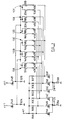
- FIG. 1 shows an assembly of six dual-valve fuel injectors 10A-10F, arranged in two banks, 10A-10C and 10D-10F.
- Each fuel injector has two actuators, one for controlling each of its two valves.
- the actuators are denoted by references 12A,12B, 14A,14B, 16A,16B, 18A,18B, 20A,20B and 22A,22B.
- One of the valves of each fuel injector is a spill valve, corresponding to actuators denoted with a reference sign 'A', and the other valve is a nozzle control valve, corresponding to actuators denoted with a reference sign 'B'.
- Each actuator comprises a winding through which a current may be passed to actuate the associated valve.
- the actuators 12A-22A and 12B-22B are controlled by means of two high side switches 24A,24B and six low side switches 26A-26F.
- the switches are field effect transistors (FETs).
- FETs field effect transistors
- the low side switches 26A-F are arranged such that each one controls two actuators of the same type i.e. each low side switch 26A-26F either controls two actuators for spill valves or two actuators for nozzle control valves.
- the low side switches 26A-26F and the high side switches 24A,24B are under the control of an electronic control unit (ECU) (not shown) which would be familiar to a person skilled in the art and will not be described in further detail.
- the high and low side switches may be located within the ECU.
- the low side switches are arranged in two banks, 26A-26C and 26D-26F, each bank having an associated resistor 28A,28B.
- Each bank of fuel injectors 10A-C and 10D-F is connected to a different one of the high side switches 24A,24B.
- the actuator connections to the high side switches 24A,24B are such that each of the two actuators sharing a common low side switch is connected to a different one of the high side switches 24A,24B.
- the actuators 12A and 18A are connected, on one side, to the low side switch 26A whereas the other side of actuator 12A is connected to the high side switch 24A, the other side of actuator 18A being connected to the high side switch 24B.
- each actuator 12A and 18A, sharing the common low side switch 26A are also connected to the anode of a diode 30A, the cathode of which is connected to a DC supply V1.
- Diodes 30A-30F connected in this way are included for each of the actuator pairs sharing a common low side switch 26A-26F.
- the high side switches 24A,24B are connected on one side to a DC supply V1, typically a 50V supply, and on the other side to the cathode of an associated diode, 32A and 32B respectively, the anode of each diode 32A,32B being connected to ground.
- V1 typically a 50V supply
- the arrangement is such that independent current sensing, by means of the resistors 28A,28B, is possible for each of the actuators 12A-22A, 12B-22B.
- Independent current sensing through each of the actuators is desirable as it enables current glitch detection to be performed, as will be described hereinafter.
- the fuel injectors 10A-10B can be operated sequentially without overlapping.
- each of the actuators 12A,14A, 16A, 12B,14B,16B of the first bank of fuel injectors 10A-10C is achieved by closing the appropriate low side switch 26A-26F.
- Actuator selection and current holding in a selected actuator is performed by each low-side switch with the corresponding high side switch turned on. Recirculation occurs through the high side switch 24A, and the corresponding diode 30A-30F, when the corresponding low side switch is turned off.
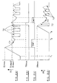
- FIG. 2(a) shows the current waveform, I S , through the winding of actuator 12A controlling the spill valve
- Figure 2(d) shows the current waveform, I B , through the winding of actuator 12B controlling the nozzle valve.
- the continuous lines shown in Figures 2(a) and 2(d) represent the current which is sensed by the sensing resistor, 28A or 28B, whereas the dashed line portions 70,72 represent the actual current flowing through the actuator winding.
- the current, I S through actuator 12A increases at a high rate, during which period both the high and low side switches 24A,26A are closed.
- the peak current value, I SMAX is reached the high side switch 24A is opened and the current decays at a slower rate through the resistor 28A, providing the low side switch 26A remains closed.
- the high side switch 24A is closed again, the current, I S , will start to increase.
- the low side switch 26A is opened, and with the high side switch closed, recirculation occurs through the high side switch 24A and diode 30A, causing the current through the winding of the actuator to decay.
- the current, I S , through the actuator 12A can be held about a mean holding value, as shown in Figure 2(a), with the current decaying when the low side switch 26A is open and the current increasing when the low side switch 26A is closed. Pulsing the low side switch 26A in this way thereby serves to regulate the current through the winding of the actuator 12A.
- the opening and closing of the low side switch 26A will be referred to as the "chopping mode".
- the actuator 12A In the chopping mode, the actuator 12A is supplied with the mean holding current such that it actuates upon the spill valve to hold it in the desired position within the fuel injector 10A.
- both the high side switch 24A and the low side switch 26A are opened to allow rapid decay of the current, I S , to zero.
- actuator 12B for controlling the nozzle control valve of the fuel injector 10A is also controlled by high side switch 24B and low side switch 26D.
- Figure 2(d) shows the current waveform, I N , in the actuator 12B controlling the nozzle control valve of fuel injector 10A.
- the current increase is initiated at time t3 by closing the low side switch 26D (the high side switch 24A already being closed).
- the current is increased to a maximum value at which time the low side switch 26D is opened so that the current recirculates back through the high side switch 24A and diode 30D.
- the current can be maintained at a mean holding value, using the chopping mode as described above, by opening and closing the low side switch 26D.
- glitch window pulse GW1
- Figure 2(b) which is used to open and close the high and low side switches 24A,26A.
- the glitch window pulse GW1 is provided by the ECU as for the other switch control pulses.
- glitch window GW2 can be used to open the high side switch 24A and to close the low side switch 26D to enable the recirculating current associated with actuator 12B to be sensed by means of resistor 28B.
- current glitch detection can be performed to determine when closure of the nozzle control valve occurs, at which time the chopping mode is initiated to provide the mean holding current required to hold the nozzle valve in the required position.
- An advantage of the drive circuit of the present invention is that, because the low side switch 26D is not on the same low side switch bank as switch 26A, the current through actuator 12B can be sensed independently from the current through corresponding actuator 12A as the recirculating current in each case is sensed by a different resistor 28A,28B. It will be appreciated that it is important to ensure that the current waveforms applied to the two actuators of a common fuel injector (e.g. actuators 12A and 12B) are chosen such that glitch windows can be introduced at the desired time on one of the actuators without substantially affecting the operation of the other.
- a common fuel injector e.g. actuators 12A and 12B
- an additional pulse, T RMAX may be used, as shown in Figure 2B.
- the pulse, T RMAX is initiated immediately before glitch window pulse GW2 is applied and serves to maintain the high side switch 24A in the closed position and the low side switch 26A in the closed position for a fractionally longer period than when in regular chopping mode, such that the current I S increases above the value of I SMAX1 to the slightly higher value I SMAX2 . In this way, the decay of current I S is prevented from decaying to too low a value during glitch window pulse GW2.
- Control of each of the actuators of the five other fuel injectors, 10B-10F can be implemented in the same way as described above for actuators 12A and 12B of fuel injector 10A. It will be appreciated that for any particular actuator, a relatively fast current decay occurs in recirculation mode when the corresponding low side switch and the corresponding high side switch are both open. If, at this time, the other low side switch associated with the same high side switch remains closed, the current decay in the actuator corresponding to this other low side switch will decay slowly.
- the drive circuit enables independent current sensing in each of the actuators of a dual-valve fuel injector, while requiring only marginally more complex sensing circuitry than is required for a single-valve fuel injector. It is possible to interchange the high side switches 24A,24B with the low side switches 26A-26F such that the current sensing resistor 28A,28B are located in connection with the high side switches 24A,24A. However, this does have the undesirable effect of there being a high, common voltage across the resistors 28A,28B.
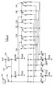
- Figure 3 shows a modification of the control circuit shown in Figure 1 which has an improved level of fault tolerance.
- series blocking diodes 40A,40B, 42A,42B, 44A,44B, 46A,46B,48A,48B, 50A,50B are included in the path between the actuators 12A,12B-22A-22B and their respective low side switches 26A-26F.
- the diodes 40A,40B-50A,50B ensure that no current can flow back through the shorted connection.
- the three fuel injectors of the other fuel injector bank, 10-10C or 10D-10F can still be kept running, providing a so-called "limp home capability".
- the diodes also provide the advantage that any small currents which may undesirably flow through a unpowered actuator during the time when a powered actuator is in recirculation mode, are blocked.
- the diodes 40A,40B-50A,50B should be arranged close to or inside the ECU providing the drive circuit control pulses to protect against the fuel injector return wires shorting to ground. Locating the diodes 40A,40B-50A,50B within the ECU does, however, require six additional connectors on the ECU. Alternatively, the diodes may be located with the ECU connector cover, although may give rise to manufacturing difficulties.
- the actuators of the fuel injectors 10A-10F shown in Figures 1 and 3 are powered by means of a DC supply, V1, typically supplying 50V.
- V1 typically supplying 50V.
- a high voltage regulated supply can be used to power the actuators by means of a battery voltage, such as a 12V car battery, in combination with a booster converter and by storing energy in a tank capacitor which is subsequently used to power the actuators.
- a battery voltage such as a 12V car battery
- booster converter such as a battery voltage
- the drive circuit of the present invention requires more power than an assembly of single-valve fuel injectors due to the increased number of actuators in the assembly. This requires the use of a booster converter of increased size.
- the control circuit shown in Figure 4 comprises two high side switches 24A and 24B connected to the cathode of a blocking diode 32A and 32B respectively, the anode of each blocking diode being connected to ground.
- High side switch 24B is connected to a further switch 60, referred to as a high boost switch, connecting the high side switch 24B to a high voltage supply, V2, typically 50V.
- the high boost switch 60 is connected to ground via a tank capacitor 62.
- a battery 66 such as a 12V car battery, also supplies power to the high side switches 24A,24B (i.e. in place of voltage supply V1 in Figures 1 and 3) through a diode 64 to prevent current flow back to the battery 66.
- the high boost switch 60 When the high boost switch 60 is closed, the high supply voltage supplies the current required for the fast current increase upon e.g. after time t1 in Figure 2(a). When the switch 60 is opened, the battery voltage 66 is available, via the diode 64, to provide the chopping mode holding current. Thus, by controlling the opening and closing of the high boost switch 60, either a higher supply voltage (V2) or a lower voltage (battery 66) can be supplied to the selected actuator.
- V2 higher supply voltage
- battery 66 battery 66
- a relatively fast current decay occurs in both actuators when both the corresponding low side switches and the corresponding high side switch are open.
- the inductive energy stored in the actuators is returned to the high voltage supply V2 via the "parasitic" diode between the source and the drain of the high boost switch 60. If one of the low side switches associated with the same high side switch remains closed, the current will decay more slowly in the actuator and the current in the other actuator of the fuel injector will decay at the faster rate, returning its energy to the high voltage supply V3.
- mixed-voltage operation provided by DC supply V3 and battery 66, is shown in Figure 4 in combination with the use of series blocking diodes 40A,40B-50A,50B, mixed voltage operation may also be employed in embodiments of the invention which do not include these diodes.
- the fuel injector assemblies shown in Figures 1,3 and 4 may be employed in an internal combustion engine having six cylinders, one fuel injector 10A-10F being associated with a different one of the six cylinders and each fuel injector having two valves. It will be appreciated, however, that the control circuit may be adapted to control an increased or reduced number of dual-valve fuel injectors.
Landscapes
- Engineering & Computer Science (AREA)
- Chemical & Material Sciences (AREA)
- Combustion & Propulsion (AREA)
- Mechanical Engineering (AREA)
- General Engineering & Computer Science (AREA)
- Electrical Control Of Air Or Fuel Supplied To Internal-Combustion Engine (AREA)
- Fuel-Injection Apparatus (AREA)
- Relay Circuits (AREA)
Abstract
Description
Claims (9)
- A drive circuit for controlling at least one device (10A) having first and second electromagnetically operable actuators (12A, 12B), the drive circuit having first and second terminals for connection to voltage supply means (V 1) and comprising a first controllable switch (24A) in connection with one side of the actuators (12A, 12B) and the first terminal, each actuator having an associated second controllable switch (26A, 26D) in connection with the other side of the respective actuator, whereby opening and closing of the first and second switches serves to control selection and actuation of the actuators (12A, 12B),
characterised in that the drive circuit further comprises sensing means (28A, 28B) for providing independent sensing of the current flowing through each of the actuators (12A, 12B), each actuator having an associated diode (30A, 30D) in connection with the respective second controllable switch (26A, 26D) to ensure current flows through the sensing means (28A, 28B) when the first controllable switch (24A) is opened and the second controllable switch (26A, 26D) is closed. - The drive circuit as claimed in Claim 1, wherein the sensing means takes the form of two resistors (28A, 28B), one resistor being associated with a different one of the two actuators (12A, 12B), each resistor (28A, 28B) being connected on one side to the second controllable switch (26A, 26D) associated with the respective actuator (12A, 12B).
- The drive circuit as claimed in Claim 1 or Claim 2, further comprising an electronic control unit arranged to provide switching pulses to the first and second controllable switches (24A; 26A, 26D).
- The drive circuit as claimed in Claim 3, wherein the electronic control unit is arranged to provide switching control pulses which include current glitch detection pulses to initiate switching of the first and second controllable switches (24A; 26A, 26D) when current sensing is required.
- The drive circuit as claimed in any of the preceding claims, further comprising a blocking diode (40A, 40B) connected between each actuator (12A, 12B) and the respective second controllable switch (26A, 26D) to prevent any unintentional short-circuit current flow through the respective actuator.
- The drive circuit as claimed in Claim 5, wherein the blocking diodes (40A, 40B) are located within an electronic control unit.
- The drive circuit as claimed in any of the preceding claims, the drive circuit being arranged to control a plurality of devices (10A-10F) arranged in two banks and comprising separate first controllable switches (24A, 24B) for each of the two banks, the second controllable switches being arranged such that each second controllable switch (26A-26F) is common to actuators of devices in both banks.
- The drive circuit as claimed in any of the preceding claims, wherein the circuit is arranged to be powered by a DC supply voltage (66) connected to the first and second terminals.
- The drive circuit as claimed in any of Claim 1 to 8, further comprising a third controllable switch (60) to enable mixed-voltage operation, whereby selection of a higher voltage supply provides an initial higher current to an actuator to initiate actuation thereof and selection of a lower voltage supply provides a subsequent lower current to the actuator sufficient to hold the actuator (12A, 12B) in a desired position within the device (10A), selection being effected by switching of the third controllable switch (60).
Applications Claiming Priority (2)
| Application Number | Priority Date | Filing Date | Title |
|---|---|---|---|
| GB9905897 | 1999-03-16 | ||
| GBGB9905897.6A GB9905897D0 (en) | 1999-03-16 | 1999-03-16 | Drive circuit |
Publications (2)
| Publication Number | Publication Date |
|---|---|
| EP1036929A2 true EP1036929A2 (en) | 2000-09-20 |
| EP1036929A3 EP1036929A3 (en) | 2001-09-05 |
Family
ID=10849633
Family Applications (1)
| Application Number | Title | Priority Date | Filing Date |
|---|---|---|---|
| EP00302132A Withdrawn EP1036929A3 (en) | 1999-03-16 | 2000-03-16 | Drive circuit |
Country Status (3)
| Country | Link |
|---|---|
| US (1) | US6292036B1 (en) |
| EP (1) | EP1036929A3 (en) |
| GB (1) | GB9905897D0 (en) |
Cited By (1)
| Publication number | Priority date | Publication date | Assignee | Title |
|---|---|---|---|---|
| WO2007125356A1 (en) * | 2006-04-24 | 2007-11-08 | Edwards Limited | Method of actuating solenoid valves |
Families Citing this family (3)
| Publication number | Priority date | Publication date | Assignee | Title |
|---|---|---|---|---|
| GB0216347D0 (en) * | 2002-07-13 | 2002-08-21 | Delphi Tech Inc | Control method |
| US7485984B2 (en) * | 2006-05-12 | 2009-02-03 | Delphi Technologies, Inc. | Control module |
| US9611797B2 (en) * | 2012-10-30 | 2017-04-04 | National Instruments Corporation | Direct injection flexible multiplexing scheme |
Family Cites Families (5)
| Publication number | Priority date | Publication date | Assignee | Title |
|---|---|---|---|---|
| US4961006A (en) * | 1989-06-22 | 1990-10-02 | Motorola, Inc. | Inductively loaded switching transistor circuit |
| US5264736A (en) * | 1992-04-28 | 1993-11-23 | Raytheon Company | High frequency resonant gate drive for a power MOSFET |
| US5499157A (en) * | 1994-11-09 | 1996-03-12 | Woodward Governor Company | Multiplexed electronic fuel injection control system |
| JP2809147B2 (en) * | 1995-08-30 | 1998-10-08 | 日本電気株式会社 | Piezo transformer drive circuit |
| US5729164A (en) * | 1996-01-11 | 1998-03-17 | Alliedsignal Truck Brake Systems Co. | Solenoid driver interface custom integrated circuit |
-
1999
- 1999-03-16 GB GBGB9905897.6A patent/GB9905897D0/en not_active Ceased
-
2000
- 2000-03-15 US US09/525,351 patent/US6292036B1/en not_active Expired - Fee Related
- 2000-03-16 EP EP00302132A patent/EP1036929A3/en not_active Withdrawn
Cited By (1)
| Publication number | Priority date | Publication date | Assignee | Title |
|---|---|---|---|---|
| WO2007125356A1 (en) * | 2006-04-24 | 2007-11-08 | Edwards Limited | Method of actuating solenoid valves |
Also Published As
| Publication number | Publication date |
|---|---|
| US6292036B1 (en) | 2001-09-18 |
| GB9905897D0 (en) | 1999-05-05 |
| EP1036929A3 (en) | 2001-09-05 |
Similar Documents
| Publication | Publication Date | Title |
|---|---|---|
| US7057870B2 (en) | Inductive load driver circuit and system | |
| US4905120A (en) | Driver circuit for solenoid operated fuel injectors | |
| US5701870A (en) | Programmable fuel injector current waveform control and method of operating same | |
| US9062624B2 (en) | Fuel injector communication system | |
| JPH059626B2 (en) | ||
| US4862866A (en) | Circuit for the piloting of inductive loads, particularly for operating the electro-injectors of a diesel-cycle internal combustion engine | |
| EP1903201B1 (en) | Valve control strategy and controller | |
| US5936827A (en) | Device for controlling at least one electromagnetic load | |
| US5499157A (en) | Multiplexed electronic fuel injection control system | |
| US5752482A (en) | System for integrally controlling current flow through number of inductive loads | |
| US6526945B2 (en) | Control circuit for controlling at least one solenoid valve for fuel metering in an internal combustion engine | |
| US4933805A (en) | Circuit for controlling inductive loads, particularly for the operation of the electro-injectors of a diesel-engine | |
| DE19734895A1 (en) | Device and method for controlling at least one capacitive actuator/final control element e.g. for motor vehicle fuel injection system | |
| US6292036B1 (en) | Drive circuit | |
| US7349193B2 (en) | Solenoid driver with high-voltage boost and reverse current capability | |
| EP2635784A1 (en) | Method for operating a switching element | |
| EP0305344B1 (en) | A circuit for the piloting of inductive loads, particularly for operating the electro-injectors of a diesel-cycle internal combustion engine | |
| US6973920B2 (en) | Method and device for storing and/or reading out data of a fuel metering system | |
| DE69804801T2 (en) | POWER CONTROL CIRCUIT FOR AN ELECTROMAGNETIC ACTUATOR, SUCH AS INJECTION VALVE OR ELECTROMAGNETIC VALVE | |
| US5150687A (en) | Supply circuit for operation of an electromagnetic load | |
| US6591813B1 (en) | Matrix injector driver circuit | |
| US5877931A (en) | Device for controlling inductive loads, in particular of injectors of an internal combustion engine injection system | |
| JP2001032740A (en) | Injector drive method | |
| EP1669577B1 (en) | Inductive load driver with overcurrent detection | |
| CA1335901C (en) | Driver circuit for solenoid operated fuel injectors |
Legal Events
| Date | Code | Title | Description |
|---|---|---|---|
| PUAI | Public reference made under article 153(3) epc to a published international application that has entered the european phase |
Free format text: ORIGINAL CODE: 0009012 |
|
| AK | Designated contracting states |
Kind code of ref document: A2 Designated state(s): AT BE CH CY DE DK ES FI FR GB GR IE IT LI LU MC NL PT SE |
|
| AX | Request for extension of the european patent |
Free format text: AL;LT;LV;MK;RO;SI |
|
| PUAL | Search report despatched |
Free format text: ORIGINAL CODE: 0009013 |
|
| AK | Designated contracting states |
Kind code of ref document: A3 Designated state(s): AT BE CH CY DE DK ES FI FR GB GR IE IT LI LU MC NL PT SE |
|
| AX | Request for extension of the european patent |
Free format text: AL;LT;LV;MK;RO;SI |
|
| STAA | Information on the status of an ep patent application or granted ep patent |
Free format text: STATUS: THE APPLICATION HAS BEEN WITHDRAWN |
|
| 17P | Request for examination filed |
Effective date: 20011102 |
|
| 18W | Application withdrawn |
Withdrawal date: 20011205 |