EP1036922A2 - Direct fuel injection-type spark-ignition internal combustion engine - Google Patents
Direct fuel injection-type spark-ignition internal combustion engine Download PDFInfo
- Publication number
- EP1036922A2 EP1036922A2 EP00105475A EP00105475A EP1036922A2 EP 1036922 A2 EP1036922 A2 EP 1036922A2 EP 00105475 A EP00105475 A EP 00105475A EP 00105475 A EP00105475 A EP 00105475A EP 1036922 A2 EP1036922 A2 EP 1036922A2
- Authority
- EP
- European Patent Office
- Prior art keywords
- fuel
- fuel injection
- internal combustion
- combustion engine
- spark plug
- Prior art date
- Legal status (The legal status is an assumption and is not a legal conclusion. Google has not performed a legal analysis and makes no representation as to the accuracy of the status listed.)
- Granted
Links
Images


Classifications
-
- F—MECHANICAL ENGINEERING; LIGHTING; HEATING; WEAPONS; BLASTING
- F02—COMBUSTION ENGINES; HOT-GAS OR COMBUSTION-PRODUCT ENGINE PLANTS
- F02B—INTERNAL-COMBUSTION PISTON ENGINES; COMBUSTION ENGINES IN GENERAL
- F02B23/00—Other engines characterised by special shape or construction of combustion chambers to improve operation
- F02B23/08—Other engines characterised by special shape or construction of combustion chambers to improve operation with positive ignition
- F02B23/10—Other engines characterised by special shape or construction of combustion chambers to improve operation with positive ignition with separate admission of air and fuel into cylinder
- F02B23/104—Other engines characterised by special shape or construction of combustion chambers to improve operation with positive ignition with separate admission of air and fuel into cylinder the injector being placed on a side position of the cylinder
-
- F—MECHANICAL ENGINEERING; LIGHTING; HEATING; WEAPONS; BLASTING
- F02—COMBUSTION ENGINES; HOT-GAS OR COMBUSTION-PRODUCT ENGINE PLANTS
- F02B—INTERNAL-COMBUSTION PISTON ENGINES; COMBUSTION ENGINES IN GENERAL
- F02B75/00—Other engines
- F02B75/12—Other methods of operation
- F02B2075/125—Direct injection in the combustion chamber for spark ignition engines, i.e. not in pre-combustion chamber
-
- F—MECHANICAL ENGINEERING; LIGHTING; HEATING; WEAPONS; BLASTING
- F02—COMBUSTION ENGINES; HOT-GAS OR COMBUSTION-PRODUCT ENGINE PLANTS
- F02F—CYLINDERS, PISTONS OR CASINGS, FOR COMBUSTION ENGINES; ARRANGEMENTS OF SEALINGS IN COMBUSTION ENGINES
- F02F1/00—Cylinders; Cylinder heads
- F02F1/24—Cylinder heads
- F02F2001/244—Arrangement of valve stems in cylinder heads
- F02F2001/245—Arrangement of valve stems in cylinder heads the valve stems being orientated at an angle with the cylinder axis
-
- Y—GENERAL TAGGING OF NEW TECHNOLOGICAL DEVELOPMENTS; GENERAL TAGGING OF CROSS-SECTIONAL TECHNOLOGIES SPANNING OVER SEVERAL SECTIONS OF THE IPC; TECHNICAL SUBJECTS COVERED BY FORMER USPC CROSS-REFERENCE ART COLLECTIONS [XRACs] AND DIGESTS
- Y02—TECHNOLOGIES OR APPLICATIONS FOR MITIGATION OR ADAPTATION AGAINST CLIMATE CHANGE
- Y02T—CLIMATE CHANGE MITIGATION TECHNOLOGIES RELATED TO TRANSPORTATION
- Y02T10/00—Road transport of goods or passengers
- Y02T10/10—Internal combustion engine [ICE] based vehicles
- Y02T10/12—Improving ICE efficiencies
Definitions
- the fuel injection valve injects fuel in a shape that is conically concentrated. Therefore, a relatively long period is required while the fuel injected in the last stage of fuel injection becomes a combustible mixture utilizing the heat from the wall surfaces of the combustion chamber. To ensure this period, therefore, the fuel injection end timing must be advanced. An amount of fuel which can be injected in the latter half of the compression stroke, therefore, inevitably decreases, and stratified charge combustion must be abandoned in high engine load operations in which a relatively large amount of fuel is required. It has therefore been desired to carry out the stratified charge combustion, which is effective in decreasing the consumption of fuel, over a wider range of engine operations.
- the velocity vector of each part of fuel in the direction of width thereof is converted into a synthesized velocity vector of the upward velocity vector and the horizontal velocity vector directed to the center of the opposing side wall. It is thus intended to direct all parts of fuel toward the spark plug.
- a direct fuel injection-type spark-ignition internal combustion engine comprising a spark plug, a cavity formed on the top surface of the piston, and a fuel injection valve for injecting fuel into the cavity in nearly a flat fan shape having a relatively small thickness, wherein an opposing side wall of the cavity opposed to the fuel injection valve, for leading the fuel to the vicinity of the spark plug, has an arcuate portion having a plurality of arcuate shapes in a plan view, the radius of the arcuate shape at both side parts of the arcuate portion in a plan view is smaller than the radius of arcuate shape at the center part of the arcuate portion in a plan view, and the opposing side wall has a deflecting portion to deflect the fuel toward the inside of the cavity.
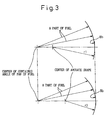
- the opposing side wall 8b of the cavity 8 has an arcuate portion having a plurality of arcuate shapes in a plan view.
- the radius R2 of the arcuate shape at both side parts in a plan view is smaller than the radius R1 of the arcuate shape at the central part in a plan view.
- the connection portions between different radii of arcuate shapes are made smooth.
- the centers of radii R1 and R2 of the arcuate shapes are separately positioned on the center line of the contained angle of the fan of fuel, establishing such a relationship that the center of the contained angle of the fan of fuel is separated more, than these centers of radii R1 and R2, from the opposing side wall 8b.
- the horizontal distance to the spark plug 6 differs depending on the central portion and both side portions of the opposing side wall 8b, and thus, though all parts of fuel can arrive at near one point in the horizontal direction at the ignition timing, the height differs depending upon the parts of fuel.
- all parts of fuel can be concentrated nearly in a cylindrical form about a vertical line MC shown in Fig. 2. The thus formed mixture is not so lean as to deteriorate the ignition performance, and comes in contact with the ignition gap of the ignition plug 6, realizing favorable stratified charge combustion without a misfire.
- the vertical line MC for concentrating the fuel is separated away from the center line PC of the spark plug toward the fuel injection valve 7, and thus the burned combustible mixture is allowed to freely expand in a wide space in the cavity 8 on the side of the fuel injection valve 7, making it possible to reliably prevent the unburned combustible mixture from being dispersed.
Landscapes
- Engineering & Computer Science (AREA)
- Chemical & Material Sciences (AREA)
- Combustion & Propulsion (AREA)
- Mechanical Engineering (AREA)
- General Engineering & Computer Science (AREA)
- Combustion Methods Of Internal-Combustion Engines (AREA)
Abstract
Description
Claims (9)
- A direct fuel injection-type spark-ignition internal combustion engine comprising a spark plug, a cavity formed on the top surface of the piston, and a fuel injection valve for injecting fuel into said cavity in nearly the flat fan shape having a relatively small thickness, wherein an opposing side wall of said cavity opposite to said fuel injection valve, for leading said fuel to the vicinity of said spark plug, has an arcuate portion having a plurality of arcuate shapes in a plan view, the radius of arcuate shape at the both side parts of said arcuate portion in a plan view is smaller than the radius of arcuate shape at the center part of said arcuate portion in a plan view and said opposing side wall has a deflecting portion to deflect said fuel toward the inside of said cavity.
- A direct fuel injection-type spark-ignition internal combustion engine according to claim 1, wherein said deflecting portion has acute angles with respect to a horizontal plane and an acute angle of said deflecting portion positioned on the center part of said opposing side wall is larger than an acute angle of said deflecting portion positioned on the both side parts of said opposing side wall.
- A direct fuel injection-type spark ignition internal combustion engine according to claim 2, wherein the acute angle of said deflecting portion is gradually changed.
- A direct fuel injection-type spark ignition internal combustion engine according to claim 1, wherein the center vertical line for concentrating said fuel is separated away from the center line of said spark plug.
- A direct fuel injection-type spark ignition internal combustion engine according to claim 2, wherein the center vertical line for concentrating said fuel is separated away from the center line of said spark plug.
- A direct fuel injection-type spark ignition internal combustion engine according to claim 3, wherein the center vertical line for concentrating said fuel is separated away from the center line of said spark plug.
- A direct fuel injection-type spark ignition internal combustion engine according to claim 4, wherein said center vertical line for concentrating said fuel is separated away from said center line of said spark plug toward said fuel injection valve.
- A direct fuel injection-type spark ignition internal combustion engine according to claim 5, wherein said center vertical line for concentrating said fuel is separated away from said center line of said spark plug toward said fuel injection valve.
- A direct fuel injection-type spark ignition internal combustion engine according to claim 6, wherein said center vertical line for concentrating said fuel is separated away from said center line of said spark plug toward said fuel injection valve.
Applications Claiming Priority (2)
| Application Number | Priority Date | Filing Date | Title |
|---|---|---|---|
| JP07003599A JP3401206B2 (en) | 1999-03-16 | 1999-03-16 | In-cylinder injection spark ignition internal combustion engine |
| JP7003599 | 1999-03-16 |
Publications (3)
| Publication Number | Publication Date |
|---|---|
| EP1036922A2 true EP1036922A2 (en) | 2000-09-20 |
| EP1036922A3 EP1036922A3 (en) | 2001-03-21 |
| EP1036922B1 EP1036922B1 (en) | 2004-12-01 |
Family
ID=13419948
Family Applications (1)
| Application Number | Title | Priority Date | Filing Date |
|---|---|---|---|
| EP00105475A Expired - Lifetime EP1036922B1 (en) | 1999-03-16 | 2000-03-15 | Direct fuel injection-type spark-ignition internal combustion engine |
Country Status (4)
| Country | Link |
|---|---|
| US (1) | US6334426B1 (en) |
| EP (1) | EP1036922B1 (en) |
| JP (1) | JP3401206B2 (en) |
| DE (1) | DE60016298T2 (en) |
Cited By (1)
| Publication number | Priority date | Publication date | Assignee | Title |
|---|---|---|---|---|
| EP1371829A3 (en) * | 2002-06-12 | 2008-03-26 | Fuji Jukogyo Kabushiki Kaisha | In-cylinder fuel injection engine and the method of controlling the engine |
Families Citing this family (7)
| Publication number | Priority date | Publication date | Assignee | Title |
|---|---|---|---|---|
| JP3405261B2 (en) | 1999-03-30 | 2003-05-12 | トヨタ自動車株式会社 | In-cylinder injection spark ignition internal combustion engine |
| DE10026323A1 (en) * | 2000-05-26 | 2001-11-29 | Bosch Gmbh Robert | Fuel injection system |
| US6588396B1 (en) * | 2002-02-01 | 2003-07-08 | General Motors Corporation | Spark ignition direct injection engine with oval fuel spray into oblong piston bowl |
| US6892693B2 (en) * | 2003-02-12 | 2005-05-17 | Bombardier Recreational Products, Inc. | Piston for spark-ignited direct fuel injection engine |
| US6945219B2 (en) * | 2004-02-09 | 2005-09-20 | Bombardier Recreational Products Inc. | Dual zone combustion chamber |
| US7318406B2 (en) * | 2006-04-10 | 2008-01-15 | Ford Global Technologies Llc | Bowl-in-piston of a cylinder in a direct injection engine |
| US8671908B2 (en) * | 2009-07-31 | 2014-03-18 | Ford Global Technologies, Llc | Glow plug placement in a diesel engine |
Citations (1)
| Publication number | Priority date | Publication date | Assignee | Title |
|---|---|---|---|---|
| JPH09158736A (en) | 1995-12-06 | 1997-06-17 | Toyota Central Res & Dev Lab Inc | Spark ignition combustion method and spark ignition internal combustion engine |
Family Cites Families (7)
| Publication number | Priority date | Publication date | Assignee | Title |
|---|---|---|---|---|
| JPS5912120A (en) * | 1982-07-13 | 1984-01-21 | Toyota Central Res & Dev Lab Inc | Direct injection type internal combustion engine |
| JPH04237822A (en) | 1991-01-18 | 1992-08-26 | Toyota Motor Corp | Cylinder injection type internal combustion engine |
| US5259348A (en) | 1991-06-20 | 1993-11-09 | Toyota Jidosha Kabushiki Kaisha | Direct injection type engine |
| US5806482A (en) * | 1995-03-28 | 1998-09-15 | Mitsubishi Jidosha Kogyo Kabushiki Kaisha | In-cylinder injection internal combustion engine |
| EP0778403B1 (en) | 1995-03-28 | 2000-11-08 | Mitsubishi Jidosha Kogyo Kabushiki Kaisha | Cylinder injection type internal combustion engine |
| US6223715B1 (en) | 1998-03-23 | 2001-05-01 | Yamaha Hatsudoki Kabushiki Kaisha | Combustion chamber for direct injected engine |
| JP3548688B2 (en) * | 1998-07-08 | 2004-07-28 | トヨタ自動車株式会社 | In-cylinder injection spark ignition internal combustion engine |
-
1999
- 1999-03-16 JP JP07003599A patent/JP3401206B2/en not_active Expired - Fee Related
-
2000
- 2000-03-13 US US09/524,273 patent/US6334426B1/en not_active Expired - Lifetime
- 2000-03-15 EP EP00105475A patent/EP1036922B1/en not_active Expired - Lifetime
- 2000-03-15 DE DE60016298T patent/DE60016298T2/en not_active Expired - Lifetime
Patent Citations (1)
| Publication number | Priority date | Publication date | Assignee | Title |
|---|---|---|---|---|
| JPH09158736A (en) | 1995-12-06 | 1997-06-17 | Toyota Central Res & Dev Lab Inc | Spark ignition combustion method and spark ignition internal combustion engine |
Cited By (1)
| Publication number | Priority date | Publication date | Assignee | Title |
|---|---|---|---|---|
| EP1371829A3 (en) * | 2002-06-12 | 2008-03-26 | Fuji Jukogyo Kabushiki Kaisha | In-cylinder fuel injection engine and the method of controlling the engine |
Also Published As
| Publication number | Publication date |
|---|---|
| US6334426B1 (en) | 2002-01-01 |
| JP2000265842A (en) | 2000-09-26 |
| EP1036922B1 (en) | 2004-12-01 |
| DE60016298T2 (en) | 2005-11-24 |
| DE60016298D1 (en) | 2005-01-05 |
| JP3401206B2 (en) | 2003-04-28 |
| EP1036922A3 (en) | 2001-03-21 |
Similar Documents
| Publication | Publication Date | Title |
|---|---|---|
| US5335635A (en) | Combustion chamber for an internal combustion engine | |
| EP1026377B1 (en) | Direct-fuel-injection-type spark-ignition internal combustion engine | |
| JP4501832B2 (en) | Spark ignition direct injection engine | |
| EP1036922B1 (en) | Direct fuel injection-type spark-ignition internal combustion engine | |
| US6269789B1 (en) | Direct fuel injection-type spark-ignition internal combustion engine | |
| JP2000104551A (en) | Direct injection gasoline engine | |
| EP0879943B1 (en) | Cylinder direct injection spark-ignition engine | |
| US6651612B2 (en) | In-cylinder injection type spark-ignition internal combustion engine | |
| US6257199B1 (en) | Direct fuel injection-type spark-ignition internal combustion engine | |
| US6186113B1 (en) | Direct cylinder injection-type spark ignition internal combustion engine | |
| US6263855B1 (en) | Direct fuel injection-type spark-ignition internal combustion engine | |
| EP1275831B1 (en) | Direct fuel injection-type spark-ignition internal combustion engine | |
| JPH0645626Y2 (en) | Combustion chamber structure of diesel engine | |
| JP2002004864A (en) | In-cylinder injection spark ignition internal combustion engine | |
| JP2524920Y2 (en) | Direct injection internal combustion engine | |
| JPS62291425A (en) | Laminar combustion engine | |
| JP3644230B2 (en) | Piston for in-cylinder internal combustion engine | |
| JPS62291424A (en) | Laminar combustion engine | |
| JP3651467B2 (en) | In-cylinder injection spark ignition internal combustion engine | |
| WO2024201932A1 (en) | Internal combustion engine with auxiliary combustion chamber | |
| JPH09217626A (en) | Direct injection four valve diesel engine | |
| JP2000282864A (en) | Combustion chamber structure of in-cylinder injection engine | |
| JP2004324563A (en) | In-cylinder direct injection internal combustion engine | |
| JP2000303844A (en) | In-cylinder injection spark ignition internal combustion engine | |
| JPH11200863A (en) | Combustion chamber of internal combustion engine |
Legal Events
| Date | Code | Title | Description |
|---|---|---|---|
| PUAI | Public reference made under article 153(3) epc to a published international application that has entered the european phase |
Free format text: ORIGINAL CODE: 0009012 |
|
| 17P | Request for examination filed |
Effective date: 20000315 |
|
| AK | Designated contracting states |
Kind code of ref document: A2 Designated state(s): AT BE CH CY DE DK ES FI FR GB GR IE IT LI LU MC NL PT SE |
|
| AX | Request for extension of the european patent |
Free format text: AL;LT;LV;MK;RO;SI |
|
| PUAL | Search report despatched |
Free format text: ORIGINAL CODE: 0009013 |
|
| AK | Designated contracting states |
Kind code of ref document: A3 Designated state(s): AT BE CH CY DE DK ES FI FR GB GR IE IT LI LU MC NL PT SE |
|
| AX | Request for extension of the european patent |
Free format text: AL;LT;LV;MK;RO;SI |
|
| AKX | Designation fees paid |
Free format text: DE FR GB |
|
| 17Q | First examination report despatched |
Effective date: 20031114 |
|
| GRAP | Despatch of communication of intention to grant a patent |
Free format text: ORIGINAL CODE: EPIDOSNIGR1 |
|
| GRAS | Grant fee paid |
Free format text: ORIGINAL CODE: EPIDOSNIGR3 |
|
| GRAA | (expected) grant |
Free format text: ORIGINAL CODE: 0009210 |
|
| AK | Designated contracting states |
Kind code of ref document: B1 Designated state(s): DE FR GB |
|
| REG | Reference to a national code |
Ref country code: GB Ref legal event code: FG4D |
|
| RIN1 | Information on inventor provided before grant (corrected) |
Inventor name: ABE, SHIZUO Inventor name: SASAKI, KOUICHI Inventor name: SATOU, FUMIKAZU Inventor name: NOMURA, YOSHIHIRO,C/O K.K.TOYOTA CHUO KENKYUSHO Inventor name: IISAKA, SIGEMITU Inventor name: KOIKE, MAKOTO,C/O K.K.TOYOTA CHUO KENKYUSHO |
|
| REF | Corresponds to: |
Ref document number: 60016298 Country of ref document: DE Date of ref document: 20050105 Kind code of ref document: P |
|
| ET | Fr: translation filed | ||
| PLBE | No opposition filed within time limit |
Free format text: ORIGINAL CODE: 0009261 |
|
| STAA | Information on the status of an ep patent application or granted ep patent |
Free format text: STATUS: NO OPPOSITION FILED WITHIN TIME LIMIT |
|
| 26N | No opposition filed |
Effective date: 20050902 |
|
| REG | Reference to a national code |
Ref country code: GB Ref legal event code: 746 Effective date: 20081024 |
|
| PGFP | Annual fee paid to national office [announced via postgrant information from national office to epo] |
Ref country code: DE Payment date: 20130314 Year of fee payment: 14 Ref country code: FR Payment date: 20130325 Year of fee payment: 14 Ref country code: GB Payment date: 20130313 Year of fee payment: 14 |
|
| REG | Reference to a national code |
Ref country code: DE Ref legal event code: R119 Ref document number: 60016298 Country of ref document: DE |
|
| GBPC | Gb: european patent ceased through non-payment of renewal fee |
Effective date: 20140315 |
|
| REG | Reference to a national code |
Ref country code: FR Ref legal event code: ST Effective date: 20141128 |
|
| REG | Reference to a national code |
Ref country code: DE Ref legal event code: R119 Ref document number: 60016298 Country of ref document: DE Effective date: 20141001 |
|
| PG25 | Lapsed in a contracting state [announced via postgrant information from national office to epo] |
Ref country code: DE Free format text: LAPSE BECAUSE OF NON-PAYMENT OF DUE FEES Effective date: 20141001 Ref country code: FR Free format text: LAPSE BECAUSE OF NON-PAYMENT OF DUE FEES Effective date: 20140331 Ref country code: GB Free format text: LAPSE BECAUSE OF NON-PAYMENT OF DUE FEES Effective date: 20140315 |