EP1036537A2 - Vacuum cleaner - Google Patents
Vacuum cleaner Download PDFInfo
- Publication number
- EP1036537A2 EP1036537A2 EP00105411A EP00105411A EP1036537A2 EP 1036537 A2 EP1036537 A2 EP 1036537A2 EP 00105411 A EP00105411 A EP 00105411A EP 00105411 A EP00105411 A EP 00105411A EP 1036537 A2 EP1036537 A2 EP 1036537A2
- Authority
- EP
- European Patent Office
- Prior art keywords
- hose
- air passage
- vacuum cleaner
- pipe
- suction
- Prior art date
- Legal status (The legal status is an assumption and is not a legal conclusion. Google has not performed a legal analysis and makes no representation as to the accuracy of the status listed.)
- Granted
Links
- 238000005192 partition Methods 0.000 claims description 14
- 239000000428 dust Substances 0.000 abstract description 31
- 238000004140 cleaning Methods 0.000 description 9
- 238000000034 method Methods 0.000 description 9
- 230000000694 effects Effects 0.000 description 5
- 230000005856 abnormality Effects 0.000 description 4
- 238000009434 installation Methods 0.000 description 4
- 230000002093 peripheral effect Effects 0.000 description 3
- 229920005989 resin Polymers 0.000 description 3
- 239000011347 resin Substances 0.000 description 3
- 238000007664 blowing Methods 0.000 description 2
- 210000000078 claw Anatomy 0.000 description 2
- 238000001816 cooling Methods 0.000 description 2
- 238000001125 extrusion Methods 0.000 description 2
- 208000031872 Body Remains Diseases 0.000 description 1
- 230000002411 adverse Effects 0.000 description 1
- 230000003749 cleanliness Effects 0.000 description 1
- 238000004891 communication Methods 0.000 description 1
- 230000010485 coping Effects 0.000 description 1
- 230000003247 decreasing effect Effects 0.000 description 1
- 238000007599 discharging Methods 0.000 description 1
- 230000001747 exhibiting effect Effects 0.000 description 1
- 238000001914 filtration Methods 0.000 description 1
- 239000000463 material Substances 0.000 description 1
- 239000002184 metal Substances 0.000 description 1
- 229910052751 metal Inorganic materials 0.000 description 1
- 238000000465 moulding Methods 0.000 description 1
- 238000000746 purification Methods 0.000 description 1
- 229920003002 synthetic resin Polymers 0.000 description 1
- 239000000057 synthetic resin Substances 0.000 description 1
- 238000005406 washing Methods 0.000 description 1
Images





Classifications
-
- A—HUMAN NECESSITIES
- A47—FURNITURE; DOMESTIC ARTICLES OR APPLIANCES; COFFEE MILLS; SPICE MILLS; SUCTION CLEANERS IN GENERAL
- A47L—DOMESTIC WASHING OR CLEANING; SUCTION CLEANERS IN GENERAL
- A47L9/00—Details or accessories of suction cleaners, e.g. mechanical means for controlling the suction or for effecting pulsating action; Storing devices specially adapted to suction cleaners or parts thereof; Carrying-vehicles specially adapted for suction cleaners
- A47L9/24—Hoses or pipes; Hose or pipe couplings
-
- A—HUMAN NECESSITIES
- A47—FURNITURE; DOMESTIC ARTICLES OR APPLIANCES; COFFEE MILLS; SPICE MILLS; SUCTION CLEANERS IN GENERAL
- A47L—DOMESTIC WASHING OR CLEANING; SUCTION CLEANERS IN GENERAL
- A47L5/00—Structural features of suction cleaners
- A47L5/12—Structural features of suction cleaners with power-driven air-pumps or air-compressors, e.g. driven by motor vehicle engine vacuum
- A47L5/14—Structural features of suction cleaners with power-driven air-pumps or air-compressors, e.g. driven by motor vehicle engine vacuum cleaning by blowing-off, also combined with suction cleaning
Definitions
- the present invention relates to a vacuum cleaner, and particularly to a vacuum cleaner of exhaust circumfluently flowing (circulation) type for making air exhausted from a motor fan incorporated in a vacuum cleaner main body circumfluently flow into, for instance, a suction nozzle for floors through a hose and a pipe.
- vacuum cleaners which are provided for the purpose of reducing exhaust air blown out to the exterior in this manner or of improving dust-collecting effects wherein hoses, pipes and suction nozzle which are connected to vacuum cleaner main bodies are formed with suction air passages as well as exhaust air passages for making a part of or the entire air exhausted from motor fans circumfluently flow.
- hoses as well as pipes are arranged to be of concentric circular double structures wherein suction air passages are formed at inner sides while exhaust air passages are formed at outer sides.
- suction air passage While there might be considered to separate an interior of a general pipe used for suction of air only by means of a plate-like partition to form an suction air passage and an exhaust air passage, the suction air passage will accordingly assume a semicircular section so that dust is more likely to be plugged when compared to general passages of circular shapes.
- the hose needs to be of a double structure type in such exhaust circumfluently flowing type vacuum cleaners.
- vacuum cleaners there are generally employed hoses which are called one-layer and two-wiring hoses and are relatively heavy hoses incorporating therein coil wiring exhibiting conductive (so that they can be used as signal wiring) and shape-retaining characteristics. Therefore, in case of employing a double structure with such a hose, the weight of the entire hose will become excessive and results in inferior operatability and difficulty in practical use.
- a hose like an one-layer and two-wiring hose, which incorporates therein coil wiring needs to be attached and fixed to an hose-installing end of the connecting pipe in a screwing manner, and performing this operation at both ends of the double structured hose twice each, that is, four times, is quite troublesome.
- attaching and fixing needs to be performed while taking torsions in the hose into consideration. Thus, assembling processes of the hose become quite complicated.
- the present invention has been made for solving such problems, and it is an object of a first invention to achieve for a light-weighted and slim-sized pipe of an exhaust circumfluently flowing type vacuum cleaner through which a suction air passage and an exhaust air passage extend.
- a first invention relates to a vacuum cleaner wherein a hose, a pipe and a suction nozzle, which are connected to a vacuum cleaner main body incorporating therein a motor fan, are formed with a suction air passage as well as an exhaust air passage for making air exhausted from the motor fan circumfluently flow, characterized in that the pipe is composed of an inner cylindrical portion having a substantially circular section and forming the suction air passage, and an outer cylindrical portion a part of which is uniformly formed with the inner cylindrical portion and which covers the inner cylindrical portion to form the exhaust air passage.
- the invention is further characterized in that the exhaust air passage of the pipe is formed to assume a substantially crescent section and in that the outer cylindrical portion of the pipe is formed to assume a substantially circular section.
- the invention is further characterized in that a wall thickness of a partition portion for separating the air suction air passage and the exhaust air passage of the pipe is formed to be smaller than an outer wall portion of the pipe.
- the invention is further characterized in that a partition portion for separating the suction air passage and the exhaust air passage at at least one of a suction inlet side of the pipe and a suction inlet of a grip portion of the hose is indented in a depth direction by a specified distance.
- a second invention relates to a vacuum cleaner wherein a hose, a pipe and a suction nozzle, which are connected to a vacuum cleaner main body incorporating therein a motor fan, are formed with a suction air passage as well as an exhaust air passage for making air exhausted from the motor fan circumfluently flow, characterized in that the hose is arranged to be of a double structure, and in that a flexible hose incorporating therein conductive wiring is used as an outer hose for forming the exhaust air passage, while a flexible hose incorporating no conductive wiring is used as an inner hose for forming the suction air passage.
- the invention relates to a vacuum cleaner wherein a hose, a pipe and a suction nozzle, which are connected to a vacuum cleaner main body incorporating therein a motor fan, are formed with a suction air passage as well as an exhaust air passage for making air exhausted from the motor fan circumfluently flow, characterized in that the hose is arranged to be of a double structure and, in that a flexible hose incorporating therein a shape-retaining means is used as an outer hose for forming the exhaust air passage, while a flexible hose incorporating no shape-retaining means is used as an inner hose for forming the suction air passage.
- the invention is further characterized in that an inner hose-installing end of a connecting pipe of double structure, which is used for attaching one end of the hose of double structure to a hose-inserting inlet of the vacuum cleaner main body and the other end thereof to a hose grip portion, is made to extrude outwardly than an outer hose-installing end.
- the vacuum cleaner includes, in addition to a connecting pipe of double structure, which is used for attaching one end of the hose of double structure to a hose-inserting inlet of the vacuum cleaner main body and the other end thereof to a hose grip portion, an auxiliary pipe which is installed to at least one end of the inner hose and which is tightly fitted to a corresponding inner hose-installing end of the connecting pipe, and a slip off-preventing mechanism for the tightly fitted auxiliary pipe.
- the invention is further characterized in that the vacuum cleaner includes, as the slip off-preventing mechanism, an annular groove formed at an outer periphery of a fitting portion of the auxiliary pipe and an engaging member attached to the inner hose-installing end of the connecting pipe for engaging with the annular groove, wherein the auxiliary pipe attached to the inner hose and the inner hose-installing end of the connecting pipe are connected in a slidable manner in a peripheral direction.
- the invention is further characterized in that the inner hose is made to be opaque while the outer hose is made to be transparent.
- the invention is further characterized in that the pipe according to the second invention is composed of an inner cylindrical portion having a substantially circular section and forming the suction air passage and of an outer cylindrical portion a part of which is uniformly formed with the inner cylindrical portion and which covers the inner cylindrical portion to form the exhaust air passage.
- the invention is further characterized in that the exhaust air passage of the pipe according to the second invention is formed to assume a substantially crescent section and in that the outer cylindrical portion of the pipe is formed to assume a substantially circular section.
- the vacuum cleaner of floor moving type to which the present invention is applied is composed of, as shown in Fig. 1, a vacuum cleaner main body 1, a hose 2, connecting pipes 3 and a suction nozzle for floors 4 and others.
- the vacuum cleaner main body 1 incorporates therein a motor chamber 6 accumulating a motor fan 5 for suction purposes, and a dust-collecting chamber 9 using a paper pack 7 and a minute dust filter 8.
- an exhaust outlet 11 for discharging a part of air exhausted from the motor fan 5 to the exterior via an exhaust filter 10.
- passages of a part of the vacuum cleaner main body 1, the hose 2, the connecting pipes 3 and the suction nozzle for floors 4 are arranged to be of double structure.
- the passages of the above members are separated into a suction air passage A and an exhaust air passage B, and the members are in communication with each other.
- the exhaust air passage B is formed at a lower portion side of the dust-collecting chamber 9 and the motor chamber 6 of the vacuum cleaner main body 1 for making a part of air exhausted from the motor fan 5 circumfluently flow wherein this exhaust air passage B is communicated to an exhaust air passage B of a hose joint portion 20 which is attached to a hose inserting inlet 12 of the vacuum cleaner main body 1.
- the hose joint portion 20 has a double structure in which connecting pipes 20a, 20b are arranged concentrically, and both ends of the inner connecting pipe 20a forming the suction air passage A are arranged in an extruding manner wherein one end thereof is inserted into an installing portion 7a of a paper pack 7 and the exhaust air passage B formed by the outer connecting pipe 20b is communicated to the exhaust air passage B in the main body 1.
- a flexible hose 2a which is denoted as a conduit hose and is similar to a drain hose for a washing machine, is used at its inner side and that a flexible hose 2b, which is denoted as an one-layer and two wiring hose incorporating therein coil wiring 21 for providing conductive (e.g. signal wiring) and shape-retaining characteristics as generally used in a vacuum cleaner, is used at its outer side.
- a flexible hose 2a which is denoted as a conduit hose and is similar to a drain hose for a washing machine
- a flexible hose 2b which is denoted as an one-layer and two wiring hose incorporating therein coil wiring 21 for providing conductive (e.g. signal wiring) and shape-retaining characteristics as generally used in a vacuum cleaner
- conduit hose 2a does not incorporate therein coil wiring 21 unlike the one-layer and two-wiring hose 2b, it is light-weighted and is restorable without leaving deformations even if it is erroneously treaded on unlike the one-layer and two-wiring hose 2b.
- the hose 2 is attached and fixed in such a manner that the inner conduit hose 2a is first attached and adhered to an extruding end of the inner connecting pipe 20a of the joint portion 20 whereupon the outer one-layer and two-wiring hose 2b is screwed into a rib 22 which is formed at an outer surface of the outer connecting pipe 20b in a threaded manner as shown in Fig. 5.
- An installing portion of the hose 2 is covered by a cylindrical protecting cover 23.
- the other end of the hose 2 is attached and fixed to a grip portion 24 for performing operations at hand in a similar manner as above-described via connecting pipes 24a, 24b. That is, the inner conduit hose 2a is first attached and adhered to an extruding end of the inner connecting pipe 24a whereupon the outer one-layer and two-wiring hose 2b is screwed into a rib 25 that is formed at an outer surface of the outer connecting pipe 24b in a threaded manner as shown in Fig. 7. An installing portion of this hose 2 is similarly covered by a cylindrical protecting cover 26.
- the grip portion 24 so arranged that a partition portion 28 for separating the suction air passage A and the exhaust air passage B at a suction inlet 27 to which the connecting pipe 3 is attached is indented in a depth direction by a specified distance.
- a clamp 29 for attaching and fixing the connecting pipe 3.
- inner and outer connecting pipes 20a, 20b at the hose joint portion 20 and the inner and outer connecting pipes 24a, 24b at the grip portion 24 are respectively partially connected by means of a rib (not shown) to assume a concentric circular double structure.
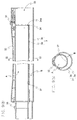
- the connecting pipes 3,3 are respectively composed, as shown in Fig. 2, of an inner cylindrical portion 3a having a substantially circular section for forming a suction A and an outer cylindrical portion 3b an upper portion of which is uniformly formed with the inner cylindrical portion 3a and which covers the inner cylindrical portion 3a to form an exhaust air passage B.
- Exhaust air which passes through the exhaust air passage B is clean air of which dust has been eliminated via the paper pack 7 and the minute dust filter 8 of the vacuum cleaner main body 1, and in view of the point that the exhaust air passage does not need to assume a substantially circular section for coping with plugging of dust as it is the case with the inner cylindrical portion 3a, the exhaust air passage B of the present embodiment assumes a substantially crescent section and the outer cylindrical portion 3b is formed to assume a substantially circular section.
- the connecting pipe 3 is capable of achieving a substantially identical shape and operatability with no sense of incompatibility even when compared with a conventional type for air suction purposes only.
- a cover 32 for covering cables or a connecting clamp 31 is attached to an upper portion of the connecting pipe 3, similarly to the prior art.
- a side of suction inlet 33 of the connecting pipe 3 for connecting the other connecting pipe 3 or the suction nozzle for floors 4 is so arranged that its partition portion (inner wall portion of inner cylindrical portion 3a) 34 for separating the suction air passage A and the exhaust air passage B is indented in a depth direction by a specified distance.
- the other end of the connecting pipe 3 is formed to assume a somewhat smaller diameter than compared to the corresponding side of the suction inlet 27 of the grip portion 24 or the suction inlet 33 of the connecting pipe 3 such that the outer cylindrical portion 3b fits to an inner periphery on the side of the suction inlets 27, 33, while an extrusion 35 is further formed at an upper portion for engaging with clamps 29, 31.
- joint tubes 4a, 4b of the suction nozzle for floors 4 are arranged to assume a concentric circular double structure, fitting portions with the connecting pipes 3 are formed similar to the above arrangement.
- a part of the air exhausted from the motor fan 5 is discharged to the exterior through the exhaust outlet 11 of the main body 1, and the rest circumfluently flows from the exhaust air passage B of the main body 1 to the suction nozzle for floors 4 by passing through the exhaust air passage B of the hose 2 and the exhaust air passage B of the connecting pipe 3. Further, together with dust which has been whirled up by this exhaust air, it is again circulated to the suction air passage A of the connecting pipe 3.
- the partition portion 34 of the suction air passage A and the exhaust air passage B between the distance L which is required for fitting the pipes be concave blowing off of dust owing to exhaust air can be eliminated.
- the distance L is approximately 40 mm in the present embodiment in view of pipe fitting and velocity of sucked and exhausted air, the present invention is not limited to this value.
- exhaust air blown out to the exterior is decreased and weakened so that there can be effectively restricted that dust within a room is whirled up while performing cleaning.
- the exhaust air to be discharged to the exterior is further purified by using the paper pack 7, minute dust filter 8 or the like. Further, since the flow velocity of exhaust air blown out from the exhaust outlet 11 becomes also smaller, filtering efficiencies of the exhaust filter 10 can be improved and purification of exhaust air can be performed in a more effective manner. This also is in line with the tendency towards cleanliness in these years.
- Fig. 9 is a structural view showing a connecting pipe 3 according to another embodiment of the first invention wherein identical references numerals are used for portions which are identical or equivalent to those of the previous embodiment.
- the wall thickness of partition portion 37 for separating exhaust air passage B and suction air passage A of the inner cylindrical portion 3a which is located inside of the outer cylindrical portion 3b and does not play a large role in terms of strength is made thinner than an outer wall portion of the outer cylindrical portion 3b from the two-dot broken like to the solid line as shown in the drawing so as to make heat of the exhaust air in the exhaust air passage B easier transmissible to the air passage air suction air passage A.
- the reason for employing the conduit hose 2a on the inner side in the embodiment shown in Figs. 1 to 8 is based on the idea that no coil wiring is necessary at the inner side owing to the outer one-layer and two-wiring hose 2b incorporating coil wiring 21. Since the conduit hose 2a does not incorporate therein coil wiring 21 unlike the one-layer and two-wiring hose 2b, there are presented advantages that it is light-weighted and restorable even if it is erroneously treaded on, leaving no deformations as it is the case with the one-layer and two-wiring hose 2b.
- the one-layer and two-wiring hose 2b wherein the coil wiring 21 is incorporated in a tube made of, for instance, PVC resin is superior than the conduit hose 2a which is formed by molding resin in a bellow-like manner.
- the one-layer and two-wiring hose 2b is formed of semitransparent PVC resin or the like.
- the one-layer and two-wiring hose 2b which is similar to those of the prior art for suction purposes only though being formed to be semitransparent, on the outer side and the light-weighted conduit hose 2a on the inner side, so that a light-weighted arrangement of the double hose 2 can be achieved while wiring arrangements to the hose grip portion 24 for performing operations at hand as will be described later and to the vacuum cleaner main body 1 remain as conventional.
- the inner conduit hose 2a will restore without leaving any deformations so that the inner conduit hose 2a will be in order as long as the outer one-layer and two-wiring hose 2b is not deformed, while in case the outer one-layer and two-wiring hose 2b is deformed, the inner conduit hose 2b will be cracked, either. In this manner, the condition of the inner hose can be recognized from the external appearance of the double hose 2 so that there can be prevented for drawbacks that the plugging of dust occurs without noticing abnormalities of the inner hose.
- the one-layer and two-wiring hose 2b which is superior in expansion characteristic is arranged at the outer side, pliability of the double hose 2 can be maintained even when being bent.
- the inner conduit hose 2a to be opaque and the outer one-layer and two-wiring hose 2b to be semitransparent, it can be achieved for improvements in external appearance owing to demanding effects of design, and despite the thicker structure of the double hose 2 than compared to an ordinary hose, the semitransparent outer one-layer and two-wiring hose 2b makes the inner conduit hose 2a visible so that the entire hose appears to be relatively thin.
- the inner conduit hose 2a through which dust passes is made to be opaque and the outer one-layer and two-wiring hose 2b through which air containing no dust after dust-collection passes to be semitransparent, dust which adheres to the inner surface of the inner conduit hose 2a cannot be seen and the inner surface of the outer one-layer and two-wiring hose 2b will not be stained, so that the external appearance of the double hose 2 will not be harmed. Further, since the condition of the inner conduit hose 2a can be observed from the exterior, there can similarly prevented for drawbacks that the plugging of dust occurs without noticing abnormalities of the inner hose.
- the only hose which is screwed into the rib 22 is the one-layer and two-wiring hose 2b which is located outside and is relative easy to be installed, and the conduit hose 2a which is located inside and is hard to be installed just needs to be inserted in a straight manner and adhered so that this can be easily performed.
- the hose-installing end therefor is extruding more outside than the hose-installing end of the outer connecting pipe 20b so that the outer connecting pipe 20b will be of no hindrance and installation can be easily performed. Therefore, assembling processes of the double hose 2 can be further simplified.
- the only hose which is screwed into the rib 25 is the one-layer and two-wiring hose 2b which is located outside and is relative easy to be installed, and the inner conduit hose 2a just needs to be inserted in a straight manner and adhered so that this can be easily performed.
- the hose-installing end therefor is extruding more outside than the hose-installing end of the outer connecting pipe 24b so that the outer connecting pipe 24b will be of no hindrance and installation can be easily performed. Therefore, assembling processes of the double hose 2 can be further simplified.
- Figs. 10 to 12 are structural views for showing another embodiment of the second invention wherein identical references numerals are used for portions which are identical or equivalent to those of the previous embodiment.
- the illustrated embodiment as shown in Fig. 10 or Fig. 11, comprises an auxiliary pipe 200 that is attached to one end (grip portion 24 side) of the conduit hose 2a which is the inner hose and that is tightly fitted to the inner hose-installing end of the connecting pipe 24a on the grip portion 24 side, and a slip off-preventing mechanism 201 for the tightly fitted auxiliary pipe 200.
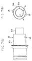
- the slip off-preventing mechanism 201 is composed of an annular grove 203 formed at an outer periphery of a fitting portion 202 of the auxiliary pipe 200 and a C ring member 205 which is attached through an installing hole 204 formed at the inner hose-installing end of the connecting pipe 24a for engaging with the annular groove 203 of the auxiliary pipe fitting portion 202.
- the slip off-preventing mechanism serves as not only performing slip off-preventing function but also connecting the auxiliary pipe 200 installed at the conduit hose 2a and the inner hose-installing end of the connecting pipe 24a in a slidable manner in a peripheral direction.
- the C ring member 205 is installed in such a manner that a side of one long piece 206 shown in Fig. 12(b) is inserted from the installing hole 204 to the fitting groove 203 while a claw 208 which is formed at the other side to be elastic through a notch 207 is pushed into the installing hole 204, thereby the claw 208 is caught at the end edge of the installing hole 204 so that it does not come off.
- numeral 24d denotes a rib which connects the inner and outer connecting pipes 24a, 24b for forming a concentric circular double structure.
- the auxiliary pipe 200 is attached and adhered to one end of the inner conduit hose 2a while the other end of the conduit hose 2a is attached and adhered to an extruding end of the inner connecting pipe 20a of the joint portion 20 which is inserted to the side of the vacuum cleaner main body 1, similarly to the previous embodiments, and the outer one-layer and two-wiring hose 2b is further attached and fixed by screwing it to the rib 22 formed at the outer surface of the outer connecting pipe 20b. In this manner, assembly of the joint portion 20 at the main body side is completed.
- the auxiliary pipe 200 which is installed to one end of the conduit hose 2a as explained above is tightly fitted to the inner hose-installing end of the connecting pipes 24a, 24b which are attached to the hose grip portion 24, and the C ring member 205 is fitted to the installing hole 204 formed at the inner hose-installing end in the above-described manner.
- the conduit hose 2a is installed at the inner connecting pipe 24a in a slidable manner.
- the one-layer and two-wiring hose 2b is attached and fixed by being screwed to the rib 25 formed at the outer surface of the outer connecting pipe 24b.
- the present embodiment makes it possible to perform installing of the inner conduit hose 2a to the connecting pipe 24a in quite an easy manner while eliminating torsions, and there can be omitted for measures such as twisting the conduit hose 2a in an opposite direction in view of torsion, so that assembling processes for the double hose 2 can be extremely simplified.
- the present invention is not limited to this arrangement, and the invention is also applicable to a hose referred to as a two-layer and four-wiring hose incorporating therein signal wiring and electric power wiring (for power brushes); a hose incorporating conductive wiring (e.g. copper wiring) which do not present shape-retaining characteristics so much while the hose itself is made to assume shape-retaining characteristics; or a hose incorporating a coil-like member (shape-retaining means) made of metal or synthetic resin and having shape-retaining characteristics.
- a hose referred to as a two-layer and four-wiring hose incorporating therein signal wiring and electric power wiring (for power brushes) for power brushes
- a hose incorporating conductive wiring e.g. copper wiring
- shape-retaining means made of metal or synthetic resin and having shape-retaining characteristics.
- outer hose one-layer and two-wiring hose 2b
- outer hose one-layer and two-wiring hose 2b
- effects similar to the above-described ones can be achieved if it exhibits transparent characteristics, regardless of whether it is semitransparent or transparent.
- the first invention is so arranged that the pipe is composed of an inner cylindrical portion having a substantially circular section and forming the suction air passage and an outer cylindrical portion a part of which is uniformly formed with the inner cylindrical portion and which covers the inner cylindrical portion to form the exhaust air passage.
- a wall thickness of a partition portion for separating the suction air passage and the exhaust air passage of the pipe is formed to be smaller than an outer wall portion.
- the partition portion for separating the suction air passage and the exhaust air passage at a suction inlet side of the pipe or at a suction inlet of a grip portion of the hose is indented in a depth direction by a specified distance.
- the hose is arranged to be of a double structure, and a flexible hose incorporating therein conductive wiring is used as an outer hose for forming the exhaust air passage while a flexible hose incorporating no conductive wiring is used as an inner hose for forming the suction air passage.
- a light-weighted arrangement of the double hose through which the suction air passage and the exhaust air passage extend can be achieved while wiring arrangements to the hose grip portion for performing operations at hand or to the vacuum cleaner main body remain as conventional owing to the omission of conductive wiring for the inner hose.
- the hose by making the hose to be of a double structure, by employing a flexible hose incorporating therein a shape-retaining means as an outer hose for forming the exhaust air passage, and by employing a flexible hose incorporating no shape-retaining means as an inner hose for forming the suction air passage, there can be achieved for a light-weighted structure for the double hose through which the suction air passage and the exhaust air passage extend since no shape-retaining means are incorporated in the inner hose, and a vacuum cleaner of exhaust circumfluently flowing type can be easily put into practice.
- the inner hose-installing end of a connecting pipe of double structure which is used for attaching one end of the hose of double structure to a hose-inserting inlet of the vacuum cleaner main body and the other end thereof to a hose grip portion, is made to extrude outwardly than an outer hose-installing end.
- a connecting pipe of double structure which is used for attaching one end of the hose of double structure to a hose-inserting inlet of the vacuum cleaner main body and the other end thereof to a hose grip portion, an auxiliary pipe which is installed to at least one end of the inner hose and which is tightly fitted to a corresponding inner hose-installing end of the connecting pipe; and a slip off-preventing mechanism for the tightly fitted auxiliary pipe.
- an annular groove which is formed at an outer periphery of a fitting portion of the auxiliary pipe, and an engaging member which is attached to the inner hose-installing end of the connecting pipe for engaging with the annular groove, wherein the auxiliary pipe attached to the inner hose and the inner hose-installing end of the connecting pipe are connected in a slidable manner in a peripheral direction.
- the outer hose makes the inner hose visible owing to the transparent characteristics thereof so that the entire hose appears to be relatively thin. Further, since the inner conduit hose through which dust passes is made to be opaque and the outer one-layer and two-wiring hose through which air containing no dust after dust-collection passes to be semitransparent, dust which adheres to the inner surface of the inner conduit hose cannot be seen and the inner surface of the outer one-layer and two-wiring hose will not be stained, and the external appearance of the double hose will not be harmed. Further, since the condition of the inner conduit hose can be observed from the exterior, there can similarly prevented for drawbacks that the plugging of dust occurs without noticing abnormalities of the inner hose.
- a vacuum cleaner wherein a hose, a pipe and a suction nozzle, which are connected to a vacuum cleaner main body incorporating therein a motor fan, are formed with a suction air passage as well as an exhaust air passage for making air exhausted from the motor fan circumfluently flow.
- the pipe is composed of an inner cylindrical portion having a substantially circular section and forming the suction air passage, and an outer cylindrical portion a part of which is uniformly formed with the inner cylindrical portion and which covers the inner cylindrical portion to form the exhaust air passage.
Landscapes
- Engineering & Computer Science (AREA)
- Mechanical Engineering (AREA)
- Electric Vacuum Cleaner (AREA)
- Electric Suction Cleaners (AREA)
- Filters For Electric Vacuum Cleaners (AREA)
- Addition Polymer Or Copolymer, Post-Treatments, Or Chemical Modifications (AREA)
Abstract
Description
Claims (10)
- A vacuum cleaner wherein a hose, a pipe and a suction nozzle, which are connected to a vacuum cleaner main body incorporating therein a motor fan, are formed with a suction air passage as well as an exhaust air passage for making air exhausted from the motor fan circumfluently flow, characterized in that the pipe is composed of an inner cylindrical portion having a substantially circular section and forming the suction air passage, and an outer cylindrical portion a part of which is uniformly formed with the inner cylindrical portion and which covers the inner cylindrical portion to form the exhaust air passage.
- The vacuum cleaner of claim 1, wherein the exhaust air passage of the pipe is formed to assume a substantially crescent section and the outer cylindrical portion of the pipe is formed to assume a substantially circular section.
- The vacuum cleaner of Claim 1, wherein a wall thickness of a partition portion for separating the air suction air passage and the exhaust air passage of the pipe is formed to be smaller than an outer wall portion of the pipe.
- The vacuum cleaner of Claim 1, wherein a partition portion for separating the suction air passage and the exhaust air passage at at least one of a suction inlet side of the pipe and a suction inlet of a grip portion of the hose is indented in a depth direction by a specified distance.
- A vacuum cleaner wherein a hose, a pipe and a suction nozzle, which are connected to a vacuum cleaner main body incorporating therein a motor fan, are formed with a suction air passage as well as an exhaust air passage for making air exhausted from the motor fan circumfluently flow, characterized in that the hose is arranged to be of a double structure, and in that a flexible hose incorporating therein conductive wiring is used as an outer hose for forming the exhaust air passage, while a flexible hose incorporating no conductive wiring is used as an inner hose for forming the suction air passage.
- A vacuum cleaner wherein a hose, a pipe and a suction nozzle, which are connected to a vacuum cleaner main body incorporating therein a motor fan, are formed with a suction air passage as well as an exhaust air passage for making air exhausted from the motor fan circumfluently flow, characterized in that the hose is arranged to be of double structure, and in that a flexible hose incorporating therein a shape-retaining means is used as an outer hose for forming the exhaust air passage, while a flexible hose incorporating no shape-retaining means is used as an inner hose for forming the suction air passage.
- The vacuum cleaner of Claim 5, wherein an inner hose-installing end of a connecting pipe of double structure, which is used for attaching one end of the hose of double structure to a hose-inserting inlet of the vacuum cleaner main body and the other end thereof to a hose grip portion, is made to extrude outwardly than an outer hose-installing end.
- The vacuum cleaner of Claim 5, wherein the inner hose is made to be opaque while the outer hose is made to be transparent.
- The vacuum cleaner of Claim 6, wherein an inner hose-installing end of a connecting pipe of double structure, which is used for attaching one end of the hose of double structure to a hose-inserting inlet of the vacuum cleaner main body and the other end thereof to a hose grip portion, is made to extrude outwardly than an outer hose-installing end.
- The vacuum cleaner of Claim 6, wherein the inner hose is made to be opaque while the outer hose is made to be transparent.
Applications Claiming Priority (4)
| Application Number | Priority Date | Filing Date | Title |
|---|---|---|---|
| JP6786399 | 1999-03-15 | ||
| JP11067863A JP2000262437A (en) | 1999-03-15 | 1999-03-15 | Electric vacuum cleaner |
| JP07158599A JP3229863B2 (en) | 1999-03-17 | 1999-03-17 | Electric vacuum cleaner |
| JP7158599 | 1999-03-17 |
Publications (3)
| Publication Number | Publication Date |
|---|---|
| EP1036537A2 true EP1036537A2 (en) | 2000-09-20 |
| EP1036537A3 EP1036537A3 (en) | 2001-09-19 |
| EP1036537B1 EP1036537B1 (en) | 2005-09-21 |
Family
ID=26409070
Family Applications (1)
| Application Number | Title | Priority Date | Filing Date |
|---|---|---|---|
| EP00105411A Expired - Lifetime EP1036537B1 (en) | 1999-03-15 | 2000-03-14 | Vacuum cleaner |
Country Status (4)
| Country | Link |
|---|---|
| US (1) | US6243915B1 (en) |
| EP (1) | EP1036537B1 (en) |
| AT (1) | ATE304808T1 (en) |
| DE (1) | DE60022698D1 (en) |
Families Citing this family (20)
| Publication number | Priority date | Publication date | Assignee | Title |
|---|---|---|---|---|
| DE10131175B4 (en) * | 2001-06-29 | 2008-06-19 | BSH Bosch und Siemens Hausgeräte GmbH | vacuum cleaner |
| CN1124417C (en) * | 1999-04-20 | 2003-10-15 | 三洋电机株式会社 | Motor wind blower and motor dust cleaner thereof |
| US6957472B2 (en) * | 1999-05-21 | 2005-10-25 | Vortex Hc, Llc | Cannister and upright vortex vacuum cleaners |
| JP2001169980A (en) * | 1999-12-15 | 2001-06-26 | Sanyo Electric Co Ltd | Electric vacuum cleaner |
| US6616722B1 (en) | 2000-05-09 | 2003-09-09 | Hmi Industries, Inc. | Room air cleaner |
| US6511531B1 (en) | 2001-01-26 | 2003-01-28 | Hmi Industries, Inc. | Room air filtering and freshening device |
| US6488744B2 (en) | 2001-03-19 | 2002-12-03 | Hmi Industries, Inc. | Filter system |
| US6725500B2 (en) | 2001-05-03 | 2004-04-27 | Vortex, L.L.C. | Air recirculating surface cleaning device |
| US20050217065A1 (en) * | 2001-05-03 | 2005-10-06 | Allen Donavan J | Air recirculating surface cleaning device |
| US20040134024A1 (en) * | 2001-05-03 | 2004-07-15 | Allen Donavan J. | Air recirculating surface cleaning device |
| DK174937B1 (en) * | 2001-09-26 | 2004-03-08 | Slagteriernes Forskningsinst | Suction head for cleaning the surface of carcass parts |
| US6687952B1 (en) | 2002-01-07 | 2004-02-10 | Hmi Industries, Inc. | Wet vacuum cleaner attachment for vacuum cleaners |
| US7018438B2 (en) * | 2002-03-29 | 2006-03-28 | Hmi Industries, Inc. | Filtering system |
| RU2250745C2 (en) * | 2003-06-03 | 2005-04-27 | Закрытое акционерное общество "Завод экспериментального машиностроения Ракетно-космический корпорации "Энергия" имени С.П. Королева" | Vacuum cleaner (variants) |
| JP4049729B2 (en) * | 2003-10-29 | 2008-02-20 | 三洋電機株式会社 | Hose for vacuum cleaner |
| JP2006034537A (en) * | 2004-07-26 | 2006-02-09 | Sanyo Electric Co Ltd | Electric vacuum cleaner and swirling type dust collecting device |
| US20070039123A1 (en) * | 2005-08-16 | 2007-02-22 | Jared Bird | Vacuum cleaner |
| US20100263162A1 (en) * | 2009-04-15 | 2010-10-21 | Song Alan A | Vacuum cleaning system |
| DE102009021596B4 (en) * | 2009-05-15 | 2011-04-28 | Fischer Rohrtechnik Gmbh | Telescopic pipe system for a vacuum cleaner |
| CN103989442B (en) * | 2014-05-04 | 2016-03-30 | 苏州市宏伟电器有限公司 | A kind of electricity conductive hose of dust collector |
Family Cites Families (18)
| Publication number | Priority date | Publication date | Assignee | Title |
|---|---|---|---|---|
| US2012640A (en) * | 1931-11-25 | 1935-08-27 | Shipman Bennet Carroll | Suction cleaner |
| US2064344A (en) * | 1933-08-25 | 1936-12-15 | Charles A Good | Combination blower and suction sweeper |
| BE638323A (en) * | 1963-10-04 | 1900-01-01 | ||
| US3461478A (en) * | 1966-05-02 | 1969-08-19 | Bernard Taylor | Apparatus for cleaning surfaces |
| FR1542802A (en) * | 1967-09-22 | 1968-10-18 | Pneumatic vacuum cleaner particularly intended for dust removal | |
| DE2218351A1 (en) * | 1972-04-15 | 1973-11-15 | Emil M Leidinger | DUST PRESSURE AND SUCTION SYSTEM |
| CA972510A (en) * | 1973-03-16 | 1975-08-12 | Henry Loetkeman | Hygienic vacuum cleaner with a circulating air flow |
| US4277640A (en) * | 1979-04-26 | 1981-07-07 | Automation Industries, Inc. | Electric current-carrying hose assembly having end fittings enclosing an electrical switch and/or a circuit-breaking device |
| US4316304A (en) * | 1980-09-04 | 1982-02-23 | Parise & Sons, Inc. | Double disconnect, waterproof electrical connector assembly for electrified vacuum hose for wet/dry vacuum cleaner |
| ES2108157T3 (en) * | 1992-04-23 | 1997-12-16 | T P A Impex Spa | MULTI-PURPOSE HOUSEHOLD APPARATUS. |
| US5647092A (en) * | 1992-10-26 | 1997-07-15 | Miwa Science Laboratory Inc. | Recirculating type cleaner |
| DE9312607U1 (en) * | 1993-08-23 | 1993-10-28 | Electrostar Schöttle GmbH & Co, 73262 Reichenbach | Suction and blowing device |
| US5459901A (en) * | 1994-01-14 | 1995-10-24 | Bissell Inc. | Hose and wand assembly for water extraction machine |
| FR2725609A3 (en) * | 1994-10-18 | 1996-04-19 | Jacqueline Patrick | Suction head with integral compressed air jet for cleaning dust and sand from textile floor coverings in buildings or vehicles |
| JPH09135795A (en) * | 1995-11-14 | 1997-05-27 | Kazuichi Tsukamoto | Electric vacuum cleaner |
| JPH09285426A (en) * | 1996-04-24 | 1997-11-04 | Yasuo Abe | Vacuum cleaner |
| JPH1043102A (en) * | 1996-08-06 | 1998-02-17 | Hitachi Ltd | Electric vacuum cleaner |
| TW475414U (en) * | 1997-12-24 | 2002-02-01 | Toshiba Tec Kk | Vacuum cleaner |
-
2000
- 2000-03-13 US US09/524,788 patent/US6243915B1/en not_active Expired - Fee Related
- 2000-03-14 AT AT00105411T patent/ATE304808T1/en not_active IP Right Cessation
- 2000-03-14 DE DE60022698T patent/DE60022698D1/en not_active Expired - Lifetime
- 2000-03-14 EP EP00105411A patent/EP1036537B1/en not_active Expired - Lifetime
Also Published As
| Publication number | Publication date |
|---|---|
| EP1036537A3 (en) | 2001-09-19 |
| ATE304808T1 (en) | 2005-10-15 |
| EP1036537B1 (en) | 2005-09-21 |
| DE60022698D1 (en) | 2006-02-02 |
| US6243915B1 (en) | 2001-06-12 |
Similar Documents
| Publication | Publication Date | Title |
|---|---|---|
| US6243915B1 (en) | Vacuum cleaner | |
| US7485164B2 (en) | Dust collection unit for vacuum cleaner | |
| US7556661B2 (en) | Dust collection unit and vacuum cleaner with same | |
| EP0985372B1 (en) | Vacuum-cleaner | |
| KR100809741B1 (en) | Flexible hose and vacuum cleaner with same | |
| KR100359066B1 (en) | Electric cleaner | |
| KR100414799B1 (en) | Electric cleaner and it's hose | |
| JP3831635B2 (en) | Vacuum cleaner and vacuum cleaner hose | |
| JP2000262445A (en) | Electric vacuum cleaner | |
| KR100369409B1 (en) | Electric cleaner | |
| CN113876264A (en) | Cleaning device | |
| JP2002000521A (en) | Vacuum cleaner and hose for vacuum cleaner | |
| JP3129485B2 (en) | Hose connection pipe for vacuum cleaner | |
| KR100359069B1 (en) | Hoses for an Electric Cleaner and an Electric Cleaner | |
| JP2001299653A (en) | Vacuum cleaner, pipe for vacuum cleaner and hose for vacuum cleaner | |
| JP3229879B2 (en) | Hose for vacuum cleaner and vacuum cleaner | |
| JP2000350686A (en) | Vacuum cleaner | |
| KR100346655B1 (en) | Hoses for an Electric Cleaner and an Electric Cleaner | |
| CN218943198U (en) | Dust cup assembly and dust collector | |
| JP2000300482A (en) | Electric vacuum cleaner | |
| KR20010049847A (en) | An Electric Cleaner and Hoses for it | |
| JP2001120478A (en) | Electric vacuum cleaner | |
| HK1027731B (en) | Vacuum-cleaner | |
| KR100403504B1 (en) | A handle for vacuum-cleaner | |
| JP2003174984A (en) | Vacuum cleaner and hose for vacuum cleaner |
Legal Events
| Date | Code | Title | Description |
|---|---|---|---|
| PUAI | Public reference made under article 153(3) epc to a published international application that has entered the european phase |
Free format text: ORIGINAL CODE: 0009012 |
|
| AK | Designated contracting states |
Kind code of ref document: A2 Designated state(s): AT BE CH CY DE DK ES FI FR GB GR IE IT LI LU MC NL PT SE |
|
| AX | Request for extension of the european patent |
Free format text: AL;LT;LV;MK;RO;SI |
|
| PUAL | Search report despatched |
Free format text: ORIGINAL CODE: 0009013 |
|
| AK | Designated contracting states |
Kind code of ref document: A3 Designated state(s): AT BE CH CY DE DK ES FI FR GB GR IE IT LI LU MC NL PT SE |
|
| AX | Request for extension of the european patent |
Free format text: AL;LT;LV;MK;RO;SI |
|
| RIC1 | Information provided on ipc code assigned before grant |
Free format text: 7A 47L 9/24 A, 7A 47L 5/14 B, 7A 47L 9/08 B |
|
| 17P | Request for examination filed |
Effective date: 20020204 |
|
| AKX | Designation fees paid |
Free format text: AT BE CH CY DE DK ES FI FR GB GR IE IT LI LU MC NL PT SE |
|
| 17Q | First examination report despatched |
Effective date: 20040105 |
|
| GRAP | Despatch of communication of intention to grant a patent |
Free format text: ORIGINAL CODE: EPIDOSNIGR1 |
|
| GRAS | Grant fee paid |
Free format text: ORIGINAL CODE: EPIDOSNIGR3 |
|
| GRAA | (expected) grant |
Free format text: ORIGINAL CODE: 0009210 |
|
| AK | Designated contracting states |
Kind code of ref document: B1 Designated state(s): AT BE CH CY DE DK ES FI FR GB GR IE IT LI LU MC NL PT SE |
|
| PG25 | Lapsed in a contracting state [announced via postgrant information from national office to epo] |
Ref country code: LI Free format text: LAPSE BECAUSE OF FAILURE TO SUBMIT A TRANSLATION OF THE DESCRIPTION OR TO PAY THE FEE WITHIN THE PRESCRIBED TIME-LIMIT Effective date: 20050921 Ref country code: IT Free format text: LAPSE BECAUSE OF FAILURE TO SUBMIT A TRANSLATION OF THE DESCRIPTION OR TO PAY THE FEE WITHIN THE PRESCRIBED TIME-LIMIT;WARNING: LAPSES OF ITALIAN PATENTS WITH EFFECTIVE DATE BEFORE 2007 MAY HAVE OCCURRED AT ANY TIME BEFORE 2007. THE CORRECT EFFECTIVE DATE MAY BE DIFFERENT FROM THE ONE RECORDED. Effective date: 20050921 Ref country code: BE Free format text: LAPSE BECAUSE OF FAILURE TO SUBMIT A TRANSLATION OF THE DESCRIPTION OR TO PAY THE FEE WITHIN THE PRESCRIBED TIME-LIMIT Effective date: 20050921 Ref country code: FI Free format text: LAPSE BECAUSE OF FAILURE TO SUBMIT A TRANSLATION OF THE DESCRIPTION OR TO PAY THE FEE WITHIN THE PRESCRIBED TIME-LIMIT Effective date: 20050921 Ref country code: AT Free format text: LAPSE BECAUSE OF FAILURE TO SUBMIT A TRANSLATION OF THE DESCRIPTION OR TO PAY THE FEE WITHIN THE PRESCRIBED TIME-LIMIT Effective date: 20050921 Ref country code: NL Free format text: LAPSE BECAUSE OF FAILURE TO SUBMIT A TRANSLATION OF THE DESCRIPTION OR TO PAY THE FEE WITHIN THE PRESCRIBED TIME-LIMIT Effective date: 20050921 Ref country code: CH Free format text: LAPSE BECAUSE OF FAILURE TO SUBMIT A TRANSLATION OF THE DESCRIPTION OR TO PAY THE FEE WITHIN THE PRESCRIBED TIME-LIMIT Effective date: 20050921 |
|
| REG | Reference to a national code |
Ref country code: GB Ref legal event code: FG4D |
|
| REG | Reference to a national code |
Ref country code: CH Ref legal event code: EP |
|
| REG | Reference to a national code |
Ref country code: IE Ref legal event code: FG4D |
|
| REF | Corresponds to: |
Ref document number: 60022698 Country of ref document: DE Date of ref document: 20051027 Kind code of ref document: P |
|
| PG25 | Lapsed in a contracting state [announced via postgrant information from national office to epo] |
Ref country code: SE Free format text: LAPSE BECAUSE OF FAILURE TO SUBMIT A TRANSLATION OF THE DESCRIPTION OR TO PAY THE FEE WITHIN THE PRESCRIBED TIME-LIMIT Effective date: 20051221 Ref country code: DK Free format text: LAPSE BECAUSE OF FAILURE TO SUBMIT A TRANSLATION OF THE DESCRIPTION OR TO PAY THE FEE WITHIN THE PRESCRIBED TIME-LIMIT Effective date: 20051221 Ref country code: GR Free format text: LAPSE BECAUSE OF FAILURE TO SUBMIT A TRANSLATION OF THE DESCRIPTION OR TO PAY THE FEE WITHIN THE PRESCRIBED TIME-LIMIT Effective date: 20051221 |
|
| PG25 | Lapsed in a contracting state [announced via postgrant information from national office to epo] |
Ref country code: DE Free format text: LAPSE BECAUSE OF FAILURE TO SUBMIT A TRANSLATION OF THE DESCRIPTION OR TO PAY THE FEE WITHIN THE PRESCRIBED TIME-LIMIT Effective date: 20051222 |
|
| PG25 | Lapsed in a contracting state [announced via postgrant information from national office to epo] |
Ref country code: ES Free format text: LAPSE BECAUSE OF FAILURE TO SUBMIT A TRANSLATION OF THE DESCRIPTION OR TO PAY THE FEE WITHIN THE PRESCRIBED TIME-LIMIT Effective date: 20060101 |
|
| REF | Corresponds to: |
Ref document number: 60022698 Country of ref document: DE Date of ref document: 20060202 Kind code of ref document: P |
|
| PG25 | Lapsed in a contracting state [announced via postgrant information from national office to epo] |
Ref country code: PT Free format text: LAPSE BECAUSE OF FAILURE TO SUBMIT A TRANSLATION OF THE DESCRIPTION OR TO PAY THE FEE WITHIN THE PRESCRIBED TIME-LIMIT Effective date: 20060221 |
|
| NLV1 | Nl: lapsed or annulled due to failure to fulfill the requirements of art. 29p and 29m of the patents act | ||
| PG25 | Lapsed in a contracting state [announced via postgrant information from national office to epo] |
Ref country code: IE Free format text: LAPSE BECAUSE OF NON-PAYMENT OF DUE FEES Effective date: 20060314 |
|
| PG25 | Lapsed in a contracting state [announced via postgrant information from national office to epo] |
Ref country code: LU Free format text: LAPSE BECAUSE OF NON-PAYMENT OF DUE FEES Effective date: 20060331 Ref country code: MC Free format text: LAPSE BECAUSE OF NON-PAYMENT OF DUE FEES Effective date: 20060331 |
|
| REG | Reference to a national code |
Ref country code: CH Ref legal event code: PL |
|
| PLBE | No opposition filed within time limit |
Free format text: ORIGINAL CODE: 0009261 |
|
| STAA | Information on the status of an ep patent application or granted ep patent |
Free format text: STATUS: NO OPPOSITION FILED WITHIN TIME LIMIT |
|
| 26N | No opposition filed |
Effective date: 20060622 |
|
| PG25 | Lapsed in a contracting state [announced via postgrant information from national office to epo] |
Ref country code: FR Free format text: LAPSE BECAUSE OF FAILURE TO SUBMIT A TRANSLATION OF THE DESCRIPTION OR TO PAY THE FEE WITHIN THE PRESCRIBED TIME-LIMIT Effective date: 20061020 |
|
| EN | Fr: translation not filed | ||
| REG | Reference to a national code |
Ref country code: IE Ref legal event code: MM4A |
|
| PGFP | Annual fee paid to national office [announced via postgrant information from national office to epo] |
Ref country code: GB Payment date: 20070314 Year of fee payment: 8 |
|
| GBPC | Gb: european patent ceased through non-payment of renewal fee |
Effective date: 20080314 |
|
| PG25 | Lapsed in a contracting state [announced via postgrant information from national office to epo] |
Ref country code: FR Free format text: LAPSE BECAUSE OF FAILURE TO SUBMIT A TRANSLATION OF THE DESCRIPTION OR TO PAY THE FEE WITHIN THE PRESCRIBED TIME-LIMIT Effective date: 20050921 Ref country code: CY Free format text: LAPSE BECAUSE OF FAILURE TO SUBMIT A TRANSLATION OF THE DESCRIPTION OR TO PAY THE FEE WITHIN THE PRESCRIBED TIME-LIMIT Effective date: 20050921 |
|
| PG25 | Lapsed in a contracting state [announced via postgrant information from national office to epo] |
Ref country code: GB Free format text: LAPSE BECAUSE OF NON-PAYMENT OF DUE FEES Effective date: 20080314 |