EP1035756A2 - Method and system for driving high pressure mercury discharge lamp and image projector - Google Patents
Method and system for driving high pressure mercury discharge lamp and image projector Download PDFInfo
- Publication number
- EP1035756A2 EP1035756A2 EP00104635A EP00104635A EP1035756A2 EP 1035756 A2 EP1035756 A2 EP 1035756A2 EP 00104635 A EP00104635 A EP 00104635A EP 00104635 A EP00104635 A EP 00104635A EP 1035756 A2 EP1035756 A2 EP 1035756A2
- Authority
- EP
- European Patent Office
- Prior art keywords
- pressure mercury
- discharge lamp
- high pressure
- mercury vapour
- frequency
- Prior art date
- Legal status (The legal status is an assumption and is not a legal conclusion. Google has not performed a legal analysis and makes no representation as to the accuracy of the status listed.)
- Withdrawn
Links
Images





Classifications
-
- H—ELECTRICITY
- H05—ELECTRIC TECHNIQUES NOT OTHERWISE PROVIDED FOR
- H05B—ELECTRIC HEATING; ELECTRIC LIGHT SOURCES NOT OTHERWISE PROVIDED FOR; CIRCUIT ARRANGEMENTS FOR ELECTRIC LIGHT SOURCES, IN GENERAL
- H05B41/00—Circuit arrangements or apparatus for igniting or operating discharge lamps
- H05B41/14—Circuit arrangements
- H05B41/26—Circuit arrangements in which the lamp is fed by power derived from DC by means of a converter, e.g. by high-voltage DC
- H05B41/28—Circuit arrangements in which the lamp is fed by power derived from DC by means of a converter, e.g. by high-voltage DC using static converters
- H05B41/288—Circuit arrangements in which the lamp is fed by power derived from DC by means of a converter, e.g. by high-voltage DC using static converters with semiconductor devices and specially adapted for lamps without preheating electrodes, e.g. for high-intensity discharge lamps, high-pressure mercury or sodium lamps or low-pressure sodium lamps
- H05B41/292—Arrangements for protecting lamps or circuits against abnormal operating conditions
- H05B41/2928—Arrangements for protecting lamps or circuits against abnormal operating conditions for protecting the lamp against abnormal operating conditions
-
- Y—GENERAL TAGGING OF NEW TECHNOLOGICAL DEVELOPMENTS; GENERAL TAGGING OF CROSS-SECTIONAL TECHNOLOGIES SPANNING OVER SEVERAL SECTIONS OF THE IPC; TECHNICAL SUBJECTS COVERED BY FORMER USPC CROSS-REFERENCE ART COLLECTIONS [XRACs] AND DIGESTS
- Y02—TECHNOLOGIES OR APPLICATIONS FOR MITIGATION OR ADAPTATION AGAINST CLIMATE CHANGE
- Y02B—CLIMATE CHANGE MITIGATION TECHNOLOGIES RELATED TO BUILDINGS, e.g. HOUSING, HOUSE APPLIANCES OR RELATED END-USER APPLICATIONS
- Y02B20/00—Energy efficient lighting technologies, e.g. halogen lamps or gas discharge lamps
Definitions
- the present invention relates to a method and system for driving a high-pressure mercury vapor discharge lamp having a pair of discharge electrodes in an arc tube in which mercury and a rare gas are enclosed.
- the invention further relates to an image projector employing the lamp.
- High-pressure mercury vapor discharge lamps are known to have a high luminance and therefore utilized for a light source of such optical devices as a liquid crystal projector and the like, with the lamp being positioned so that the light emitting region (arc) is located at the focal point of a reflector mirror such as a parabolic mirror.
- a high-pressure mercury vapor discharge lamp is used as a component in such optical devices, it is necessary that loss of the light emitted from the lamp be minimized so that a high illuminance on the screen is achieved.
- a lamp used for such a light source of liquid crystal projectors have a light emitting region as close as possible to a point source. More specifically, so-called short arc lamps, which have a short light emitting region, are preferable, and in addition, high-pressure mercury vapor discharge lamps are more preferable than metal halide lamps.
- the metals enclosed therein as metal halides have a low average excitation energy, and therefore the lamps operate at a relatively low arc temperature.
- the light emitting region is not restricted in a region between the electrodes but is spread over a wide region from the center of the arc tube towards the arc tube wall, and accordingly, a point source light is difficult to be achieved by using a metal halide lamp.
- mercury which has a high average excitation energy
- the light emitting region is restricted in a small region, and thus, a light emitting region close to a point source is readily achieved.
- a mercury vapor pressure during lamp operation is made to be 200 atm. or higher, and continuous radiation components in the visible light range are thus generated by mercury molecule emission.
- the lamp has a lamp power of 50 W, and exhibits a high luminance and improved color rendering property, and is therefore suitable for the light source of liquid crystal projectors.
- a cathode luminescent spot refers to a spot at which the highest luminance is observed (the reference numerals 11a and 12a in Fig. 1) in the vicinity of a point at which electrons are emitted when each of the electrodes 11 and 12 is turned to be a cathode.
- the wandering of a cathode luminescent spot occurs.
- a minute region 11a adjacent to the tip of the electrode 11 is heated to a high temperature and thus turned to be a cathode luminescent spot at which arc is generated by thermionic emission effect.
- emission of electrons such a state of the minute region 11a being a high temperature is further maintained.
- Fig. 2B when the polarity of the applied voltage is reversed, the electrons emitted from the electrode 12 enters a wide region in the tip of the electrode 11. By the entry of the electrons, the energy from the electrons is transferred to the electrode 11, and the wide region of the tip of the electrode 11 is heated as well as the minute region 11a.
- the minute region 11a is not necessarily in the state of a higher temperature than that of the rest of the region.
- any spot in the wide region adjacent to the tip of the electrode 11 can become a temperature that can result in a cathode luminescent spot. Consequently, it can occur that, when the polarity of the applied voltage is again reversed, another minute region 11c, not the minute region 11a, is turned to be a cathode luminescent spot.
- a position of a cathode luminescent spot tends to frequently wander in the vicinity of the tip of the electrode 11. Such wandering of the cathode luminescent spot occurs either periodically or non-periodically. In addition, such wandering of the cathode luminescent spot can occur in the electrode 12 as well.
- Such wandering of the cathode luminescent spot induces a variation of a luminance distribution in the light emitting region between the electrodes 11 and 12.
- a liquid crystal projector and the like is generally configured such that light rays from the various spots in the light emitting region with a certain size are reached and superposed on the projected screen. For this reason, when a luminance distribution of the light emitting region is varied, an illuminance on the projected image is accordingly varied. Such an illuminance variation particularly raises a serious problem in the case of using a short arc lamp.
- the shape and position of the arc is regulated by the arc tube wall, and therefore wandering of a cathode luminescent spot is not easily caused. Even if the wandering is caused, undesirable effects on the illuminance variation is not considerable since the area of wandering is small relative to the arc length.
- the present inventors have also carried out a study about in what cases a viewer recognizes the illuminance variation as described above as flicker. As a result of the study, it has been found that when a variation of illuminance exceeds ⁇ 5 % of the immediately preceding illuminance and occurs approximately 60 times/second or less, the variation of illuminance is recognized as flicker, which causes a poor image quality.
- the present inventors sought a method for suppressing wandering of a cathode luminescent spot in order to prevent flicker in the projected image, and thus have accomplished the present invention.
- the above-described method for driving a high-pressure mercury vapor discharge lamp may be such that:
- the present invention also provides a driving system for a high-pressure mercury vapor discharge lamp comprising in an arc tube a pair of electrodes opposed to each other, the lamp wherein at least mercury and a rare gas are enclosed in the arc tube, the driving system operating the lamp by applying an alternating voltage between the discharge electrodes, wherein:
- the above-described driving system for a high-pressure mercury vapor discharge lamp may be such that:
- the above-described driving system for a high-pressure mercury vapor discharge lamp may further comprise:
- the present invention further provides an image projector comprising:
- the image projector of the above-described configuration it is made possible to suppress wandering of a cathode luminescent spot and thereby to prevent flicker in the projected image, and thus high quality image can be achieved.
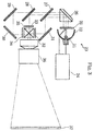
- the description details an image projector comprising a high-pressure mercury vapor discharge lamp.
- the image projector comprises a lamp unit 23 that comprises a high-pressure mercury vapor discharge lamp 21 and a parabolic mirror 22.
- a driving system 24 having a function as a ballast.
- the discussion concerning the alternating voltage having a predetermined frequency will be detailed later.
- a UV filter 25 for compensating a color temperature of the light emitted from the high-pressure mercury vapor discharge lamp 21, and a reflecting mirror 26.
- the light coming out from the reflecting mirror 26 is separated by dichroic mirrors 27 and 28 into three monochromatic light rays with the three primary colors RGB. Thereafter, with the aid of reflecting mirrors 29-31, the light rays enter liquid crystal panels 32-34 so as to be intensity-modulated.
- the intensity-modulated light rays are synthesized by a dichroic prism 35, and projected on to a screen 37 through a projection lens 36.
- other intensity-modulating devices such as DMD may be employed.
- the high pressure mercury vapor discharge lamp 21 in the lamp unit 23 comprises in an arc tube 21a a pair of discharge electrodes 21b and 21c that are composed of tungsten and shaped in a coil-like shape or a rod-like shape.
- fill materials such as mercury and a rare gas (not shown in the figure) are enclosed. It is noted that other fill materials, for example such materials as halogen gases, non-metal halides such as methyl bromide, and metal halides such as mercury bromide, may also be enclosed as a fill material.
- the high-pressure mercury vapor discharge lamp 21 is so disposed that a light emitting region 21d formed between the discharge electrodes 21b and 21c is located at the focal point of the parabolic mirror 23, and that most of the emitted light results in such a light that is approximately parallel to the optical axis of the parabolic mirror 23. More specifically, if the light emitting region 21d is an ideal point source, the light coming out from the parabolic mirror results in a perfect collimated light. However, the light emitting region 21d has a certain size (finite volume), and therefore a light coming out around the focal point of the parabolic mirror 23 results in a light slightly different from a collimated light. In view of this, the projection optical system including the projection lens 36 is so designed that the light emitted from the light emitting region 21d is projected on the screen 37 as much as possible, even when the light is a light slightly different from a collimated light.
- the description details wandering of a cathode luminescent spot and variation of a screen illuminance in the high-pressure mercury vapor discharge lamp 21, in relation to a frequency of a power source for driving the high-pressure mercury vapor discharge lamp 21.
- an apparatus as shown in Fig. 5 was prepared in order to measure a variation of a screen illuminance.
- the discharge electrodes 21b and 21c and the light emitting region 21d are enlarged, and an illuminometer 42 is placed at a position at which images 21b', 21c', and 21d', each being an image of the discharge electrodes 21b and 21c and the light emitting region 21d respectively, are formed.
- the illuminometer 42 has a light receiving part having a diameter of 10 mm, which is approximately the same size as the enlarged image of the cathode luminescent spot. In this apparatus, when a cathode luminescent spot moves, an indicated value on the illuminometer changes accordingly. Thus, by observing the change of the indicated value, a degree of wandering of a cathode luminescent spot can be measured. It is noted that, although an illuminance at a position of the illuminometer 42 is measured here, this is in effect the same as the measurement of a luminance in the vicinity of the discharge electrodes 21b and 21c.
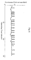
- an illuminance of the high-pressure mercury vapor discharge lamp 21 was measured with operating the lamp by applying a rectangular wave voltage with a frequency of 270 Hz. The result is shown in Fig. 6.
- an illuminance variation a state in which an illuminance is varied with reference to an immediately preceding illuminance, occurred about 40 times within approximately 30 minutes (the occurrences of the illuminance increase and decrease were each counted). These illuminance variations were caused by the wandering of a cathode luminescent spot.
- ⁇ denotes that no wandering of a cathode luminescent spot occurred (either a size of the illuminance variation was ⁇ 5 % or less, or a frequency of occurrence of the illuminance variation was 60 times/second or more)
- X denotes that the wandering of a cathode luminescent spot occurred (both a size of the illuminance variation was more than ⁇ 5 % or more, and a frequency of occurrence of the illuminance variation was less than 60 times/second). From the above Table 1, it is seen that there is a frequency band in which substantially no wandering of a cathode luminescent spot occurs in the range of a power source frequency being 20 kHz to 42 kHz.
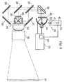
- the image projector has the same construction as the foregoing image projector of Fig. 3 except that it comprises a detector 51 for detecting wandering of a cathode luminescent spot, and that the driving system 24 comprises a frequency controller 52 for controlling (adjusting) a frequency of an applied voltage to the high-pressure mercury vapor discharge lamp 21.
- the detector 51 comprises a focusing lens 41 and an illuminometer 42, as in the apparatus of Fig. 5, and measures an illuminance of a light coming through a reflection plane of the parabolic mirror 22.
- the frequency controller 52 controls a frequency of the voltage outputted from the driving system 24 in response to the result of the measurement by the detector 51, so that wandering of a cathode luminescent spot is suppressed. Specifically, for example, the frequency controller 52 successively changes the frequency within the range of 20 kHz to 42 kHz to search a frequency at which no or little illuminance variation is caused. Having such a configuration, the image projector can suppress wandering of a cathode luminescent spot and thereby prevent flicker in the projected image, even if the high-pressure mercury vapor discharge lamp 21 has a variation in the characteristics or produce a variation due to aging.
- the illuminometer 42 is not limited to the above-described example in which the illuminance of a leaked light coning through the reflection plane of the parabolic minor 22 is measured, but may be such an illuminometer that an illuminance of an emitted light coming out of the parabolic mirror 22 is measured, or may be such an illuminometer that an illuminance on the screen 37 is measured.
Landscapes
- Projection Apparatus (AREA)
- Circuit Arrangements For Discharge Lamps (AREA)
Abstract
Description
| Lamp No. | 1 | 2 | 3 | |
| Rated Power (W) | 150 | 150 | 150 | |
| Arc Length (mm) | 1.5 | 1.7 | 1.8 | |
| Rated Power/Arc Length (W/mm) | 100 | 88.2 | 83.3 | |
| Frequency (kHz) | 20 | |||
| 21 | ||||
| 22 | ||||
| 23 | ||||
| 24 | ||||
| 25 | ||||
| 26 | ||||
| 27 | ||||
| 28 | ||||
| 29 | ||||
| 30 | ||||
| 31 | ||||
| 32 | ||||
| 33 | ||||
| 34 | ||||
| 35 | ||||
| 36 | ||||
| 37 | ||||
| 38 | ||||
| 39 | ||||
| 40 | ||||
| 41 | ||||
| 42 |
Claims (14)
- A driving system for a high pressure mercury vapour discharge lamp comprising an arc tube with a pair of electrodes opposed to each other, said lamp wherein at least mercury and a rare gas are enclosed in the arc tube, said driving system operating said lamp by applying an alternating voltage between the discharge electrodes, wherein:a frequency of said alternating voltage is such that wandering of a cathode luminescent spot generated in the vicinity of a tip of each of the discharge electrodes is suppressed.
- A driving system for a high pressure mercury vapour discharge lamp according to Claim 1, wherein:said high pressure mercury vapour discharge lamp has an arc length and a rated power such that
- A driving system for a high pressure mercury vapour discharge lamp according to any preceding claim, wherein:said frequency of the alternating voltage is within the range of 20 kHz to 42 kHz.
- A driving system for a high pressure mercury vapour discharge lamp according to any preceding claim, wherein:said frequency of the alternating voltage is such that, when an image of an arc adjacent to a tip of at least one of the discharge electrodes is projected onto a predetermined projection plane, a variation of an illuminance on said projection plane is ± 5% or smaller.
- A driving system for a high pressure mercury vapour discharge lamp according to any preceding claim, wherein:said high pressure mercury vapour discharge lamp has an arc length of 3mm or less.
- A driving system for a high pressure mercury vapour discharge lamp according to any preceding claim, wherein:a temperature of a tip of each of the discharge electrodes is 3000K or higher in said high pressure mercury vapour discharge lamp being operated.
- A driving system for a high pressure mercury vapour discharge lamp according to any preceding claim, further comprising:means for adjusting said frequency of the alternating voltage.
- A driving system for a high pressure mercury vapour discharge lamp according to any preceding claim, further comprising:means for detecting a luminance in the vicinity of a tip of at least one ofthe discharge electrodes, wherein:said means for adjusting said frequency of the alternating voltage controls said frequency of the alternating voltage to be a frequency such that wandering of a cathode luminescent spot generated in the vicinity of a tip of each of the discharge electrodes is suppressed, in response to a result detected by said means for detecting.
- A method for driving a high pressure mercury vapour discharge lamp comprising an arc tube with a pair of discharge electrodes opposed to each other, said lamp wherein at least mercury and a rare gas is enclosed in the arc tube, comprising a step of:applying an alternating voltage between the discharge electrodes, said alternating voltage having a frequency such that wandering of a cathode luminenscent spot generated in the vicinity of a tip of each of the discharge electrodes is suppressed.
- A method for driving a high pressure mercury vapour discharge lamp according to claim 9, wherein:said high pressure mercury vapour discharge lamp has an arc length and a rated power such that
- A method for driving a high pressure mercury vapour discharge lamp according to claim 9 or 10, whereinsaid high pressure mercury vapour discharge lamp has an arc length of 3mm or less
- A method for driving a high pressure mercury vapour discharge lamp according to claim 9, 10 or 11, wherein:said frequency of the alternating voltage is within the range of 20 kHz to 42 kHz.
- An image projector comprising:a high pressure mercury vapour discharge lamp comprising an arc tube with a pair of discharge electrodes opposed to each other, said lamp wherein at least mercury and a rare gas is enclosed in the arc tube,a driving system for operating said high pressure mercury vapour discharge lamp by applying an alternating voltage between the discharge electrodes, anda projection optical system using a light emitted from said high pressure mercury vapour discharge lamp as a source light to project an image onto a projection screen.
said image projector wherein:a frequency of said alternating voltage applied to the high pressure mercury vapour discharge lamp by the driving system is such that wandering of a cathode luminescent spot generated in the vicinity of a tip of each of the discharge electrodes is suppressed. - An image projector comprising a high pressure mercury vapour discharge lamp having an arc tube with a pair of discharge electrodes opposed to each other, said lamp wherein at least mercury and a rare gas is enclosed in the arc tube, a driving system according to any of Claims 1 to 8, and a projection optical system using a light emitted from said high pressure mercury vapour discharge lamp as a source light to project an image onto a projection screen.
Applications Claiming Priority (2)
| Application Number | Priority Date | Filing Date | Title |
|---|---|---|---|
| JP5820099 | 1999-03-05 | ||
| JP5820099 | 1999-03-05 |
Publications (2)
| Publication Number | Publication Date |
|---|---|
| EP1035756A2 true EP1035756A2 (en) | 2000-09-13 |
| EP1035756A3 EP1035756A3 (en) | 2003-01-22 |
Family
ID=13077402
Family Applications (1)
| Application Number | Title | Priority Date | Filing Date |
|---|---|---|---|
| EP00104635A Withdrawn EP1035756A3 (en) | 1999-03-05 | 2000-03-03 | Method and system for driving high pressure mercury discharge lamp and image projector |
Country Status (4)
| Country | Link |
|---|---|
| US (1) | US6479946B2 (en) |
| EP (1) | EP1035756A3 (en) |
| KR (1) | KR20000062743A (en) |
| TW (1) | TW472504B (en) |
Cited By (2)
| Publication number | Priority date | Publication date | Assignee | Title |
|---|---|---|---|---|
| WO2003098979A1 (en) * | 2002-05-17 | 2003-11-27 | Koninklijke Philips Electronics N.V. | Projection system |
| EP1148768A3 (en) * | 2000-04-14 | 2004-01-28 | Patent-Treuhand-Gesellschaft für elektrische Glühlampen mbH | Stabilization of gas dicharge lamps operation |
Families Citing this family (4)
| Publication number | Priority date | Publication date | Assignee | Title |
|---|---|---|---|---|
| US6715498B1 (en) * | 2002-09-06 | 2004-04-06 | Novellus Systems, Inc. | Method and apparatus for radiation enhanced supercritical fluid processing |
| JP4902528B2 (en) | 2004-05-05 | 2012-03-21 | アイマックス コーポレイション | Multi-light source high-performance stereoscopic projection system |
| CN101952775B (en) * | 2008-01-31 | 2012-02-15 | 奥斯兰姆有限公司 | lamp housing unit |
| JP4788719B2 (en) * | 2008-02-01 | 2011-10-05 | パナソニック株式会社 | High pressure discharge lamp system and projector using the same |
Family Cites Families (21)
| Publication number | Priority date | Publication date | Assignee | Title |
|---|---|---|---|---|
| US4170746A (en) * | 1977-12-27 | 1979-10-09 | General Electric Company | High frequency operation of miniature metal vapor discharge lamps |
| US4605301A (en) * | 1984-07-07 | 1986-08-12 | Ushio Denki Kabushiki Kaisha | Exposure method of semiconductor wafer by mercury-vapor lamp |
| DE3813421A1 (en) * | 1988-04-21 | 1989-11-02 | Philips Patentverwaltung | HIGH PRESSURE MERCURY VAPOR DISCHARGE LAMP |
| US4988918A (en) * | 1988-06-23 | 1991-01-29 | Toshiba Lighting And Technology Corporation | Short arc discharge lamp |
| US5057747A (en) * | 1988-11-21 | 1991-10-15 | Hughes Aircraft Company | Arc lamp stabilization |
| US5497049A (en) * | 1992-06-23 | 1996-03-05 | U.S. Philips Corporation | High pressure mercury discharge lamp |
| US5742123A (en) * | 1992-07-09 | 1998-04-21 | Toto Ltd. | Sealing structure for light-emitting bulb assembly and method of manufacturing same |
| JP3244859B2 (en) * | 1993-04-12 | 2002-01-07 | 池田デンソー株式会社 | Discharge lamp lighting device |
| DE4322115A1 (en) * | 1993-07-02 | 1995-01-12 | Patent Treuhand Ges Fuer Elektrische Gluehlampen Mbh | Metal halide high-jerk discharge lamp |
| EP0713352B1 (en) * | 1994-11-18 | 2001-10-17 | Matsushita Electric Industrial Co., Ltd. | Discharge lamp-lighting apparatus |
| US5569984A (en) * | 1994-12-28 | 1996-10-29 | Philips Electronics North America Corporation | Method and controller for detecting arc instabilities in gas discharge lamps |
| DE19534864A1 (en) * | 1995-09-20 | 1997-03-27 | Bosch Gmbh Robert | Control unit for the rapid start-up of a high-pressure gas discharge lamp |
| TW339447B (en) * | 1995-10-20 | 1998-09-01 | Matsushita Electric Industrial Co Ltd | Metal halide lamp |
| JP2915362B2 (en) * | 1996-09-27 | 1999-07-05 | ウシオ電機株式会社 | Short arc mercury lamp |
| JPH10134775A (en) * | 1996-10-31 | 1998-05-22 | Ushio Inc | Metal halide lamp |
| DE19645959A1 (en) * | 1996-11-07 | 1998-05-14 | Patent Treuhand Ges Fuer Elektrische Gluehlampen Mbh | Metal halide high pressure discharge lamp |
| DE69822058D1 (en) * | 1997-09-19 | 2004-04-08 | Matsushita Electric Industrial Co Ltd | High-pressure discharge lamp and method for producing the same |
| JP2948200B1 (en) * | 1998-04-08 | 1999-09-13 | ウシオ電機株式会社 | High pressure mercury lamp |
| JP2980882B2 (en) * | 1998-04-08 | 1999-11-22 | ウシオ電機株式会社 | High pressure mercury lamp |
| EP0964432B1 (en) * | 1998-05-12 | 2005-08-03 | Ushiodenki Kabushiki Kaisha | High pressure discharge lamp |
| DE19829600A1 (en) * | 1998-07-02 | 1999-09-23 | Seufert Gmbh Dr | Operating method and electronic ballast for high pressure ac discharge lamps |
-
2000
- 2000-03-01 US US09/517,070 patent/US6479946B2/en not_active Expired - Lifetime
- 2000-03-03 EP EP00104635A patent/EP1035756A3/en not_active Withdrawn
- 2000-03-04 TW TW089103898A patent/TW472504B/en not_active IP Right Cessation
- 2000-03-04 KR KR1020000010848A patent/KR20000062743A/en not_active Withdrawn
Cited By (2)
| Publication number | Priority date | Publication date | Assignee | Title |
|---|---|---|---|---|
| EP1148768A3 (en) * | 2000-04-14 | 2004-01-28 | Patent-Treuhand-Gesellschaft für elektrische Glühlampen mbH | Stabilization of gas dicharge lamps operation |
| WO2003098979A1 (en) * | 2002-05-17 | 2003-11-27 | Koninklijke Philips Electronics N.V. | Projection system |
Also Published As
| Publication number | Publication date |
|---|---|
| US6479946B2 (en) | 2002-11-12 |
| TW472504B (en) | 2002-01-11 |
| KR20000062743A (en) | 2000-10-25 |
| EP1035756A3 (en) | 2003-01-22 |
| US20020101163A1 (en) | 2002-08-01 |
Similar Documents
| Publication | Publication Date | Title |
|---|---|---|
| JP3971717B2 (en) | Projector including a narrow-band spectral light source to supplement a broadband spectral light source | |
| US6294870B1 (en) | High-pressure discharge lamp, high-pressure discharge lamp apparatus, and light source | |
| US20050151937A1 (en) | Light source apparatus | |
| US7138769B2 (en) | Device for operation of a high pressure discharge lamp and a projector device | |
| EP1465238A2 (en) | High-pressure mercury lamp, lamp unit, and image display device | |
| US6984943B2 (en) | Method and apparatus for lighting high pressure discharge lamp, high pressure discharge lamp apparatus, and projection-type image display apparatus | |
| EP1310984B1 (en) | High pressure mercury lamp, illumination device using the high-pressure mercury lamp, and image display apparatus using the illumination device | |
| US7830098B2 (en) | Projector and light source device thereof | |
| CN101526726B (en) | Driving method of light source apparatus for projector | |
| US5583396A (en) | Optical device with metal halide discharge lamp having enhanced starting property | |
| US20070132403A1 (en) | Light source device | |
| US6479946B2 (en) | Method and system for driving high pressure mercury discharge lamp, and image projector | |
| EP0973187B1 (en) | High pressure mercury lamp and emission device for a high pressure mercury lamp | |
| EP0901151B1 (en) | High-pressure mercury vapor discharge lamp | |
| US6570303B2 (en) | Light unit with improved heat dissipation | |
| US7400100B2 (en) | Discharge-lamp lighting apparatus and projector | |
| JP3226519B2 (en) | Driving method for high-pressure mercury vapor discharge lamp, driving apparatus for high-pressure mercury vapor discharge lamp, and image projector | |
| US8547038B2 (en) | High pressure discharge lamp lighting device | |
| US7588352B2 (en) | Optical apparatus | |
| EP0908926B1 (en) | Metal halide lamp | |
| JP3295517B2 (en) | Image display device | |
| US7744249B2 (en) | High-pressure discharge lamp, lamp unit and image display device | |
| JP4048376B2 (en) | Discharge lamp and projector | |
| JP2000311657A (en) | High pressure discharge lamp and driving method thereof | |
| JPH10247595A (en) | Light source device, light projecting device, and projector device |
Legal Events
| Date | Code | Title | Description |
|---|---|---|---|
| PUAI | Public reference made under article 153(3) epc to a published international application that has entered the european phase |
Free format text: ORIGINAL CODE: 0009012 |
|
| AK | Designated contracting states |
Kind code of ref document: A2 Designated state(s): AT BE CH CY DE DK ES FI FR GB GR IE IT LI LU MC NL PT SE |
|
| AX | Request for extension of the european patent |
Free format text: AL;LT;LV;MK;RO;SI |
|
| PUAL | Search report despatched |
Free format text: ORIGINAL CODE: 0009013 |
|
| AK | Designated contracting states |
Kind code of ref document: A3 Designated state(s): AT BE CH CY DE DK ES FI FR GB GR IE IT LI LU MC NL PT SE |
|
| AX | Request for extension of the european patent |
Free format text: AL;LT;LV;MK;RO;SI |
|
| 17P | Request for examination filed |
Effective date: 20030314 |
|
| AKX | Designation fees paid |
Designated state(s): DE FR GB |
|
| 17Q | First examination report despatched |
Effective date: 20031009 |
|
| STAA | Information on the status of an ep patent application or granted ep patent |
Free format text: STATUS: THE APPLICATION IS DEEMED TO BE WITHDRAWN |
|
| 18D | Application deemed to be withdrawn |
Effective date: 20040817 |