EP1035417A1 - Magnetic resonance apparatus and method - Google Patents
Magnetic resonance apparatus and method Download PDFInfo
- Publication number
- EP1035417A1 EP1035417A1 EP00301811A EP00301811A EP1035417A1 EP 1035417 A1 EP1035417 A1 EP 1035417A1 EP 00301811 A EP00301811 A EP 00301811A EP 00301811 A EP00301811 A EP 00301811A EP 1035417 A1 EP1035417 A1 EP 1035417A1
- Authority
- EP
- European Patent Office
- Prior art keywords
- mri
- echo
- bandwidth
- data
- sample rate
- Prior art date
- Legal status (The legal status is an assumption and is not a legal conclusion. Google has not performed a legal analysis and makes no representation as to the accuracy of the status listed.)
- Withdrawn
Links
- 238000000034 method Methods 0.000 title claims description 12
- 238000002592 echocardiography Methods 0.000 claims abstract description 25
- 238000001208 nuclear magnetic resonance pulse sequence Methods 0.000 claims abstract description 13
- 230000005540 biological transmission Effects 0.000 claims abstract description 6
- 238000009877 rendering Methods 0.000 claims abstract description 4
- 238000002595 magnetic resonance imaging Methods 0.000 claims description 36
- 238000013480 data collection Methods 0.000 claims description 4
- 230000000977 initiatory effect Effects 0.000 claims description 2
- 230000001939 inductive effect Effects 0.000 claims 1
- 238000005070 sampling Methods 0.000 description 11
- 229910052739 hydrogen Inorganic materials 0.000 description 3
- 239000001257 hydrogen Substances 0.000 description 3
- 238000003384 imaging method Methods 0.000 description 3
- UFHFLCQGNIYNRP-UHFFFAOYSA-N Hydrogen Chemical compound [H][H] UFHFLCQGNIYNRP-UHFFFAOYSA-N 0.000 description 2
- 230000005284 excitation Effects 0.000 description 2
- CWYNVVGOOAEACU-UHFFFAOYSA-N Fe2+ Chemical compound [Fe+2] CWYNVVGOOAEACU-UHFFFAOYSA-N 0.000 description 1
- 230000000712 assembly Effects 0.000 description 1
- 238000000429 assembly Methods 0.000 description 1
- 230000015556 catabolic process Effects 0.000 description 1
- 238000006731 degradation reaction Methods 0.000 description 1
- 238000002059 diagnostic imaging Methods 0.000 description 1
- 230000004907 flux Effects 0.000 description 1
- 150000002431 hydrogen Chemical class 0.000 description 1
- 239000011159 matrix material Substances 0.000 description 1
- 230000000750 progressive effect Effects 0.000 description 1
- 230000001105 regulatory effect Effects 0.000 description 1
- 238000004904 shortening Methods 0.000 description 1
- 241000894007 species Species 0.000 description 1
- 238000000264 spin echo pulse sequence Methods 0.000 description 1
- 238000009966 trimming Methods 0.000 description 1
Images


Classifications
-
- G—PHYSICS
- G01—MEASURING; TESTING
- G01R—MEASURING ELECTRIC VARIABLES; MEASURING MAGNETIC VARIABLES
- G01R33/00—Arrangements or instruments for measuring magnetic variables
- G01R33/20—Arrangements or instruments for measuring magnetic variables involving magnetic resonance
- G01R33/28—Details of apparatus provided for in groups G01R33/44 - G01R33/64
- G01R33/32—Excitation or detection systems, e.g. using radio frequency signals
- G01R33/36—Electrical details, e.g. matching or coupling of the coil to the receiver
- G01R33/3621—NMR receivers or demodulators, e.g. preamplifiers, means for frequency modulation of the MR signal using a digital down converter, means for analog to digital conversion [ADC] or for filtering or processing of the MR signal such as bandpass filtering, resampling, decimation or interpolation
Definitions
- the present invention relates to the field of magnetic resonance imaging (MRI), and finds particular application in medical diagnostic imaging. However, it is to be appreciated that the present invention is also amenable to other like applications.
- MRI magnetic resonance imaging
- a substantially uniform temporally constant main magnetic field,B 0 is generated within an examination region.
- the main magnetic field polarises the nuclear spin system of a subject being imaged within the examination region.
- Magnetic resonance is excited in dipoles which align with the magnetic field by transmitting radio frequency (RF) excitation signals into the examination region.
- RF radio frequency
- RF pulses transmitted via an RF coil assembly tip the dipoles out of alignment with the main magnetic field and cause a macroscopic magnetic moment vector to precess around an axis parallel to the main magnetic field.
- the precessing magnetic moment in turn, generates a corresponding RF magnetic resonance signal as it relaxes and returns to its former state of alignment with the main magnetic field.
- the RF magnetic resonance signal is received by the RF coil assembly, and from received signals, an image representation is reconstructed for display on a human viewable display.
- the appropriate frequency for exciting resonance in selected dipoles is governed by the Larmor equation. That is to say, the precession frequency of a dipole in a magnetic field, and hence the appropriate frequency for exciting resonance in that dipole, is a product of the gyromagnetic ratio ⁇ of the dipole and the strength of the magnetic field.
- hydrogen ( 1 H) dipoles In a 1.5 T magnetic field, hydrogen ( 1 H) dipoles have a resonance frequency of approximately 64 MHz.
- the hydrogen species is excited because of its abundance and because it yields a strong MR signal.
- typical MRI apparatus are equipped with built-in whole-body RF coils tuned to the resonant frequency for hydrogen.
- One obstacle to overcome in MRI is potential degradation in the image reconstruction due a low signal to noise ratio (SNR) in the acquired MR signals or echoes.
- SNR signal to noise ratio
- Some multi-echo sequences decrease the bandwidth of data collection for each echo in succession such that the later echoes, which are of a lower amplitude due to MR signal decay, are collected at a lower bandwidth to preserve SNR as best as possible.
- One example is multi-echo spin echo sequences which provide different contrasts in a set of images built each in turn from one of the echoes.
- these techniques do not vary the bandwidth of data collection within a single image.
- the SNR remains degraded by the noise accompanying data from the corners of k-space which are not fully visualised in the image.
- variable encoding time Recognising that central lines of k-space generally employ less phase encoding as compared to the outer lines, the VET method shortens the inter-echo spacing of a sequence while varying the data sampling window. By shortening the data sampling window time and preserving the same sampling bandwidth, time is made available for larger phase encode lobes, or the time is made available for more data samples when the desired phase encode amounts are low. This allows for the trimming of k-space corners.
- VET variable encoding time
- a method of MRI data collection with multiple data acquisitions for a single image reconstruction includes initiating an MRI pulse sequence and collecting MRI data from a first resulting echo at a first sample rate and bandwidth. Thereafter, the sample rate and bandwidth are varied such that they are set to a new sample rate and bandwidth. MRI data is then collected from a next resulting echo at the new sample rate and bandwidth. The steps of varying the bandwidth and sample rate and collection of resulting echoes are repeated for consecutive echoes until a desired amount of MRI data is collected. Ultimately, an image representation is reconstructed from the collected MRI data.
- an MRI apparatus in accordance with another aspect of the present invention, includes a main magnet that generates a substantially uniform temporally constant main magnetic field through an examination region wherein an object being imaged is positioned.
- a magnetic gradient generator produces magnetic gradients in the main magnetic field across the examination region.
- a transmission system includes an RF transmitter that drives an RF coil which is proximate to the examination region.
- a sequence control manipulates the magnetic gradient generator and the transmission system to produce an MRI pulse sequence.
- the MRI pulse sequence induces magnetic resonance echoes from the object.
- a reception system includes a receiver that receives and demodulates the echoes at varying sample rates and varying bandwidths.
- a reconstruction processor reconstructs a single image from data collected via the reception system, and an output device produces a human viewable rendering of the image.
- the present invention enables the SNR in MRI to be improved, and efficient use to be made of scan times.
- a main magnetic field control 10 controls superconducting or resistive magnets 12 such that a substantially uniform temporally constant main magnetic field, B 0 , is created along a z axis through an examination region 14 .
- a couch (not illustrated) suspends and/or positions an object to be examined, such as a patient or phantom, within the examination region 14 .
- a magnetic resonance echo means applies a series of RF and magnetic field gradient pulses to invert or excite magnetic spins, induce magnetic resonance, refocus magnetic resonance, manipulate magnetic resonance, spatially and otherwise encode the magnetic resonance, to saturate spins, and the like to generate magnetic resonance imaging sequences.
- gradient pulse amplifiers 20 apply current pulses to selected ones or pairs of gradient coil assemblies 22 to create magnetic field gradients along x, y, and z axes of the examination region 14 .
- a digital RF transmitter 24 drives a whole-body RF coil 26 to transmit RF pulses or pulse packets into the examination region 14 .
- a typical RF pulse is composed of a packet of immediately contiguous pulse segments of short duration, which taken together with each other and any applied gradients, achieve a selected magnetic resonance manipulation. For whole-body applications, the resonance signals or echoes are commonly picked up by the whole-body RFcoil 26 .
- specialised RF coils are placed contiguous to the selected region of interest.
- an insertable RF coil may be inserted surrounding a selected region at the isocentre of the bore.
- the insertable RF coil is used to excite magnetic resonance and receive magnetic resonance signals emitting from the patient in the region being examined.
- the insertable RF coil can be used to only receive resonance signals introduced by the whole-body RF coil 26 .
- the resultant RF signals are picked up by the whole-body RF coil 26 , the insertable RF coil, or other specialised RF coil and demodulated by a receiver 30 , preferably a digital receiver.
- a sequence control circuit 40 controls the gradient pulse amplifiers 20 and the transmitter 24 to generate any of a plurality of multiple echo sequences such as gradient and spin echo (GSE) imaging, fast spin echo (FSE) imaging, single shot FSE imaging, and the like.
- GSE gradient and spin echo
- FSE fast spin echo
- the receiver 30 receives a plurality of data lines in rapid succession following each RF excitation pulse.
- the RF signals are received, demodulated, and reconstructed into an image representation by a reconstruction processor 50 which applies a two-dimensional (2D) Fourier transform or other appropriate reconstruction algorithm.
- the image may represent a planar slice through the patient, an array of parallel planar slices, a three-dimensional volume, or the like.
- the image is then stored in an image memory 52 where it is accessed by a display, such as a video monitor 54 or other human viewable display or output device that provides a rendering of the resultant image.
- the invention herein is described with reference to the MRI apparatus detailed above, it is appreciated that the invention is applicable to other MRI apparatus.
- the invention is equally amenable to open geometry magnets wherein opposing pole pieces, joined by a ferrous flux return path, define an examination region therebetween.
- the sequence control 40 initiates and directs an MRI pulse sequence that generates the signal received by the receiver 30 .
- the MRI pulse sequence is assumed to be a FSE sequence. However, a single shot FSE sequence, a GSE sequence, or the like may also be employed.
- a series of RF pulses are applied to the RF coil 26 via the RF transmitter 24.
- the RF pulses include an initial 90° flip angle resonance exciting RF pulse 62 followed by a series of 180° flip angle refocusing RF pulses 64 .
- each refocusing pulse 64 results in an echo 66 .
- the echoes 66 make up the echo train of the signal.
- Each echo 66 is phase encoded by applying, to the gradient coil assembly 22 , a phase encode gradient pulse 68 preceding and following each echo 66 .
- the individual echoes 66 are separately phase encoded by varying the amplitude and/or duration of the phase encoding gradient pulse 68 .
- Each echo 66 is then collected under a readout gradient pulse 70 applied to the gradient coil assembly 22 .
- the profile of the readout gradient pulses 70 includes a central amplitude that varies between echoes 66 , and extra lobes at either end.
- This profile is constructed so that the echoes 66 are collected under readout gradients of different amplitudes while the total area under each readout gradient pulse 70 is kept the same between each refocusing RF pulse 64 .
- the receiver 30 collects and/or samples the echoes 66 under a fix duration sampling window 72 .
- each echo 66 is collected and/or sampled by the receiver 30 , the raw MR data is loaded into a memory matrix otherwise known as k-space 80 . It is this raw data in k-space 80 that is the object of the 2D Fourier transform or other appropriate reconstruction algorithm carried out by the reconstruction processor 50 .
- Each of the collected echoes 66 is mapped into its own corresponding row or horizontal line of k-space 80 such that each successively sampled data value occupies successive columns.
- the row each echo 66 is assigned to is based on the particular phase encoding imparted thereto via the phase encoding gradient pulses 68 .
- a first collected echo 66 is mapped to a central line of k-space 80 while successively collected echoes 66 are mapped to further out neighbouring lines of k-space 80 in a progressive manner.
- the collected echoes 66 have variable bandwidths and are sampled at a variable sampling rate.
- the variable bandwidths are achieved by regulating the amplitude of the readout gradient pulses 70 applied to the gradient coil assembly 22 such that a desired field of view (FOV) is maintained for each echo 66 .
- FOV field of view
- the echoes 66 are sampled at progressively narrower bandwidths under readout gradient pulses 70 having progressively smaller amplitudes during echo collection. In this manner, the later echoes 70 in the echo train which typically have lower signal strengths are sampled at the lower bandwidths thereby improving their SNR.
- the echoes 66 are collected at variable sampling rates. Being that the sampling window 72 has a fixed duration, the result is a variable number of data samples for each of the echoes 66 .
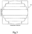
- the sampling rate (and hence the number of data points sampled) is varied such that as successive lines of k-space 80 are filled, the filled area of k-space 80 takes a circular shape. That is to say, the relationship between the phase encoding imparted by the phase encoding gradient pulses 68 and the sampling rate is such that a circular area of k-space 80 is filled with sampled data values.
- phase encoded lines assigned more toward a centre of k-space 80 have a relatively higher sampling rate such that more data points are collected within the fixed duration sampling window 72 .
- the relatively higher number data samples in turn results in relatively longer data lines.
- the filled portion of k-space 80 take on the shape of a circle.
- the SNR is improved by eliminating the corners of k-space 80 which are not fully visualised in the image reconstruction.
- other desired shapes are employed such as, for example, an elliptical shape.
Landscapes
- Physics & Mathematics (AREA)
- Condensed Matter Physics & Semiconductors (AREA)
- General Physics & Mathematics (AREA)
- Magnetic Resonance Imaging Apparatus (AREA)
Abstract
Description
- The present invention relates to the field of magnetic resonance imaging (MRI), and finds particular application in medical diagnostic imaging. However, it is to be appreciated that the present invention is also amenable to other like applications.
- In MRI, a substantially uniform temporally constant main magnetic field,B0, is generated within an examination region. The main magnetic field polarises the nuclear spin system of a subject being imaged within the examination region. Magnetic resonance is excited in dipoles which align with the magnetic field by transmitting radio frequency (RF) excitation signals into the examination region. Specifically, RF pulses transmitted via an RF coil assembly tip the dipoles out of alignment with the main magnetic field and cause a macroscopic magnetic moment vector to precess around an axis parallel to the main magnetic field. The precessing magnetic moment, in turn, generates a corresponding RF magnetic resonance signal as it relaxes and returns to its former state of alignment with the main magnetic field. The RF magnetic resonance signal is received by the RF coil assembly, and from received signals, an image representation is reconstructed for display on a human viewable display.
- The appropriate frequency for exciting resonance in selected dipoles is governed by the Larmor equation. That is to say, the precession frequency of a dipole in a magnetic field, and hence the appropriate frequency for exciting resonance in that dipole, is a product of the gyromagnetic ratio γ of the dipole and the strength of the magnetic field. In a 1.5 T magnetic field, hydrogen (1H) dipoles have a resonance frequency of approximately 64 MHz. Generally in MRI, the hydrogen species is excited because of its abundance and because it yields a strong MR signal. As a result, typical MRI apparatus are equipped with built-in whole-body RF coils tuned to the resonant frequency for hydrogen.
- One obstacle to overcome in MRI is potential degradation in the image reconstruction due a low signal to noise ratio (SNR) in the acquired MR signals or echoes.
- Previously developed methods employed to address the SNR problem have had generally limited success due to various drawbacks. Some multi-echo sequences decrease the bandwidth of data collection for each echo in succession such that the later echoes, which are of a lower amplitude due to MR signal decay, are collected at a lower bandwidth to preserve SNR as best as possible. One example is multi-echo spin echo sequences which provide different contrasts in a set of images built each in turn from one of the echoes. However, these techniques do not vary the bandwidth of data collection within a single image. Additionally, the SNR remains degraded by the noise accompanying data from the corners of k-space which are not fully visualised in the image.
- Normally, a number of rows or horizontal lines with a predetermined number of sample points are collected for an MR image. This raw data often fills k-space in a rectangular or square shape. Employment of a circular Fermi filter applied to the raw MR data to chop off the corners of k-space has been shown to improve SNR by as much as 13%. However, the disadvantage associated with this technique is that resources are wasted on the collection of data which is ultimately discarded.
- There is also the variable encoding time (VET) method. Recognising that central lines of k-space generally employ less phase encoding as compared to the outer lines, the VET method shortens the inter-echo spacing of a sequence while varying the data sampling window. By shortening the data sampling window time and preserving the same sampling bandwidth, time is made available for larger phase encode lobes, or the time is made available for more data samples when the desired phase encode amounts are low. This allows for the trimming of k-space corners.
- In accordance with one aspect of the present invention, a method of MRI data collection with multiple data acquisitions for a single image reconstruction is provided. It includes initiating an MRI pulse sequence and collecting MRI data from a first resulting echo at a first sample rate and bandwidth. Thereafter, the sample rate and bandwidth are varied such that they are set to a new sample rate and bandwidth. MRI data is then collected from a next resulting echo at the new sample rate and bandwidth. The steps of varying the bandwidth and sample rate and collection of resulting echoes are repeated for consecutive echoes until a desired amount of MRI data is collected. Ultimately, an image representation is reconstructed from the collected MRI data.
- In accordance with another aspect of the present invention, an MRI apparatus is provided. It includes a main magnet that generates a substantially uniform temporally constant main magnetic field through an examination region wherein an object being imaged is positioned. A magnetic gradient generator produces magnetic gradients in the main magnetic field across the examination region. A transmission system includes an RF transmitter that drives an RF coil which is proximate to the examination region. A sequence control manipulates the magnetic gradient generator and the transmission system to produce an MRI pulse sequence. The MRI pulse sequence induces magnetic resonance echoes from the object. A reception system includes a receiver that receives and demodulates the echoes at varying sample rates and varying bandwidths. A reconstruction processor reconstructs a single image from data collected via the reception system, and an output device produces a human viewable rendering of the image.
- The present invention enables the SNR in MRI to be improved, and efficient use to be made of scan times.
- Ways of carrying out the invention will now be described in detail, by way of example, with reference to the accompanying drawings, in which:
- FIGURE 1 is a diagrammatic illustration of an MRI apparatus in accordance with aspects of the present invention;
- FIGURE 2 is a diagrammatic illustration of an MRI pulse sequence in accordance with aspects of the present invention; and
- FIGURE 3 is a diagrammatic illustration of k-space in accordance with aspects of the present invention.
-
- With reference to FIGURE 1, a main
magnetic field control 10 controls superconducting orresistive magnets 12 such that a substantially uniform temporally constant main magnetic field, B0, is created along a z axis through anexamination region 14. A couch (not illustrated) suspends and/or positions an object to be examined, such as a patient or phantom, within theexamination region 14. A magnetic resonance echo means applies a series of RF and magnetic field gradient pulses to invert or excite magnetic spins, induce magnetic resonance, refocus magnetic resonance, manipulate magnetic resonance, spatially and otherwise encode the magnetic resonance, to saturate spins, and the like to generate magnetic resonance imaging sequences. More specifically,gradient pulse amplifiers 20 apply current pulses to selected ones or pairs of gradient coil assemblies 22 to create magnetic field gradients along x, y, and z axes of theexamination region 14. Adigital RF transmitter 24 drives a whole-body RF coil 26 to transmit RF pulses or pulse packets into theexamination region 14. A typical RF pulse is composed of a packet of immediately contiguous pulse segments of short duration, which taken together with each other and any applied gradients, achieve a selected magnetic resonance manipulation. For whole-body applications, the resonance signals or echoes are commonly picked up by the whole-body RFcoil 26. - For generating images of local regions of the subject, specialised RF coils are placed contiguous to the selected region of interest. For example, an insertable RF coil may be inserted surrounding a selected region at the isocentre of the bore. The insertable RF coil is used to excite magnetic resonance and receive magnetic resonance signals emitting from the patient in the region being examined. Alternatively, the insertable RF coil can be used to only receive resonance signals introduced by the whole-
body RF coil 26. In any event, the resultant RF signals are picked up by the whole-body RF coil 26, the insertable RF coil, or other specialised RF coil and demodulated by areceiver 30, preferably a digital receiver. - A
sequence control circuit 40 controls thegradient pulse amplifiers 20 and thetransmitter 24 to generate any of a plurality of multiple echo sequences such as gradient and spin echo (GSE) imaging, fast spin echo (FSE) imaging, single shot FSE imaging, and the like. For the selected sequence, thereceiver 30 receives a plurality of data lines in rapid succession following each RF excitation pulse. Ultimately, the RF signals are received, demodulated, and reconstructed into an image representation by areconstruction processor 50 which applies a two-dimensional (2D) Fourier transform or other appropriate reconstruction algorithm. The image may represent a planar slice through the patient, an array of parallel planar slices, a three-dimensional volume, or the like. The image is then stored in animage memory 52 where it is accessed by a display, such as avideo monitor 54 or other human viewable display or output device that provides a rendering of the resultant image. - While the invention herein is described with reference to the MRI apparatus detailed above, it is appreciated that the invention is applicable to other MRI apparatus. For example, the invention is equally amenable to open geometry magnets wherein opposing pole pieces, joined by a ferrous flux return path, define an examination region therebetween.
- In any event, with reference to FIGURE 2 and continuing reference to FIGURE 1, the
sequence control 40 initiates and directs an MRI pulse sequence that generates the signal received by thereceiver 30. For purposes of illustration herein, the MRI pulse sequence is assumed to be a FSE sequence. However, a single shot FSE sequence, a GSE sequence, or the like may also be employed. For each image reconstructed, during the application of separate sliceselect gradients 60 to the gradient coil assembly 22, a series of RF pulses are applied to theRF coil 26 via theRF transmitter 24. In the exemplary FSE sequence, the RF pulses include an initial 90° flip angle resonanceexciting RF pulse 62 followed by a series of 180° flip angle refocusingRF pulses 64. The application of each refocusingpulse 64 results in anecho 66. Collectively theechoes 66 make up the echo train of the signal. Eachecho 66 is phase encoded by applying, to the gradient coil assembly 22, a phase encodegradient pulse 68 preceding and following eachecho 66. The individual echoes 66 are separately phase encoded by varying the amplitude and/or duration of the phaseencoding gradient pulse 68. Eachecho 66 is then collected under areadout gradient pulse 70 applied to the gradient coil assembly 22. The profile of thereadout gradient pulses 70 includes a central amplitude that varies betweenechoes 66, and extra lobes at either end. This profile is constructed so that theechoes 66 are collected under readout gradients of different amplitudes while the total area under eachreadout gradient pulse 70 is kept the same between each refocusingRF pulse 64. In any event, thereceiver 30 collects and/or samples theechoes 66 under a fixduration sampling window 72. - With reference to FIGURE 3 and continuing reference to FIGURES 1 and 2, as each echo 66 is collected and/or sampled by the
receiver 30, the raw MR data is loaded into a memory matrix otherwise known as k-space 80. It is this raw data in k-space 80 that is the object of the 2D Fourier transform or other appropriate reconstruction algorithm carried out by thereconstruction processor 50. Each of the collected echoes 66 is mapped into its own corresponding row or horizontal line of k-space 80 such that each successively sampled data value occupies successive columns. The row eachecho 66 is assigned to is based on the particular phase encoding imparted thereto via the phaseencoding gradient pulses 68. Optionally, in a preferred embodiment, a first collectedecho 66 is mapped to a central line of k-space 80 while successively collected echoes 66 are mapped to further out neighbouring lines of k-space 80 in a progressive manner. - The collected echoes 66 have variable bandwidths and are sampled at a variable sampling rate. The variable bandwidths are achieved by regulating the amplitude of the
readout gradient pulses 70 applied to the gradient coil assembly 22 such that a desired field of view (FOV) is maintained for eachecho 66. In the illustrated pulse sequence, theechoes 66 are sampled at progressively narrower bandwidths underreadout gradient pulses 70 having progressively smaller amplitudes during echo collection. In this manner, the later echoes 70 in the echo train which typically have lower signal strengths are sampled at the lower bandwidths thereby improving their SNR. - Additionally, the
echoes 66 are collected at variable sampling rates. Being that thesampling window 72 has a fixed duration, the result is a variable number of data samples for each of theechoes 66. In a preferred embodiment, the sampling rate (and hence the number of data points sampled) is varied such that as successive lines of k-space 80 are filled, the filled area of k-space 80 takes a circular shape. That is to say, the relationship between the phase encoding imparted by the phaseencoding gradient pulses 68 and the sampling rate is such that a circular area of k-space 80 is filled with sampled data values. To achieve the circular shape, phase encoded lines assigned more toward a centre of k-space 80 have a relatively higher sampling rate such that more data points are collected within the fixedduration sampling window 72. The relatively higher number data samples in turn results in relatively longer data lines. As the data lines grow progressively shorter toward the edges of k-space 80, the filled portion of k-space 80 take on the shape of a circle. In this manner, similar to the application of a Fermi filter, the SNR is improved by eliminating the corners of k-space 80 which are not fully visualised in the image reconstruction. Alternately, as opposed to a circle, other desired shapes are employed such as, for example, an elliptical shape.
Claims (10)
- A method of MRI data collection with multiple data acquisitions for a single image reconstruction comprising:(a) initiating an MRI pulse sequence;(b) collecting MRI data from a first resulting echo at a first sample rate and bandwidth;(c) varying the sample rate and bandwidth such that they are set to a new sample rate and bandwidth;(d) collecting MRI data from a next resulting echo at the new sample rate and bandwidth;(e) repeating steps (c) and (d) for consecutive resulting echoes until a desired amount of MRI data is collected; and(f) reconstructing an image representation from the collected MRI data.
- A method as claimed in claim 1, wherein variations in the sample rate and bandwidth are such that a total collection time for each echo remains substantially constant.
- A method as claimed in claim 2, wherein the collection of MRI data is conducted with a fixed duration window such that varying the sample rate varies a number of data points sampled.
- A method as claimed in any one of claims 1 to 3, wherein the bandwidth is varied by changing an amplitude of a read gradient so that a predetermined FOV is maintained.
- A method as claimed in any one of claims 1 to 4, wherein the bandwidth selected for each echo is determined based on the echo's relative signal strength such that lower signal strengths correspond to lower selected bandwidths.
- Magnetic resonance imaging (MRI) apparatus comprising: a main magnet (12) that generates a substantially uniform temporally constant main magnetic field through an examination region (14) wherein an object being imaged is positioned; a magnetic gradient generator that produces magnetic gradients in the main magnetic field across the examination region (14); a transmission system which includes an RF transmitter (24) that drives an RF coil (26) which is proximate to the examination region (14); a sequence control (40) which manipulates the magnetic gradient generator and the transmission system to produce an MRI pulse sequence, said MRI pulse sequence inducing magnetic resonance echoes (66) from the object; a reception system which includes a receiver (30) that collects data from the echoes (66) at varying sample rates and varying bandwidths; a reconstruction processor (50) that reconstructs a single image from data collected via the reception system; and an output device (54) that produces a human viewable rendering of the image.
- MRI apparatus as claimed in claim 6, wherein, in use, variations in the sample rate and variations in the bandwidth are such that a total collection time for each echo (66) remains substantially constant.
- MRI apparatus as claimed in claim 6 or claim 7, wherein, in use, reception of each echo (66) is conducted with a fixed duration window (72) such that variations in sample rate translate to variations in number of data points sampled.
- MRI apparatus as claimed in any one of claims 6 to 8, wherein, in use, the bandwidth is varied by changing an amplitude of a read gradient (70) applied via the magnetic gradient generator so that a predetermined FOV is maintained.
- MRI apparatus as claimed in any one of claims 6 to 9, wherein, in use, the bandwidth selected for each echo (66) is determined based on the echo's relative signal strength such that lower signal strengths correspond to lower selected bandwidths.
Applications Claiming Priority (2)
| Application Number | Priority Date | Filing Date | Title |
|---|---|---|---|
| US09/264,831 US6255820B1 (en) | 1999-03-08 | 1999-03-08 | Variable bandwidth MRI data collection |
| US264831 | 1999-03-08 |
Publications (1)
| Publication Number | Publication Date |
|---|---|
| EP1035417A1 true EP1035417A1 (en) | 2000-09-13 |
Family
ID=23007797
Family Applications (1)
| Application Number | Title | Priority Date | Filing Date |
|---|---|---|---|
| EP00301811A Withdrawn EP1035417A1 (en) | 1999-03-08 | 2000-03-06 | Magnetic resonance apparatus and method |
Country Status (2)
| Country | Link |
|---|---|
| US (1) | US6255820B1 (en) |
| EP (1) | EP1035417A1 (en) |
Cited By (1)
| Publication number | Priority date | Publication date | Assignee | Title |
|---|---|---|---|---|
| FR2898685A1 (en) * | 2006-03-14 | 2007-09-21 | Centre Nat Rech Scient | IMAGE PROCESSING OBTAINED BY MAGNETIC RESONANCE WITH VARIABLE PASSING BANDS |
Families Citing this family (12)
| Publication number | Priority date | Publication date | Assignee | Title |
|---|---|---|---|---|
| DE10016234B4 (en) * | 2000-03-31 | 2006-12-14 | Siemens Ag | Method for nuclear magnetic resonance imaging in a curved K-space trajectory |
| JP3814157B2 (en) * | 2001-04-17 | 2006-08-23 | ジーイー・メディカル・システムズ・グローバル・テクノロジー・カンパニー・エルエルシー | MRI equipment |
| US7603156B2 (en) * | 2003-07-02 | 2009-10-13 | Ge Medical Systems Global Technology Co., Llc | Systems and methods for phase encode placement |
| US7564874B2 (en) | 2004-09-17 | 2009-07-21 | Uni-Pixel Displays, Inc. | Enhanced bandwidth data encoding method |
| US8798340B2 (en) * | 2009-11-10 | 2014-08-05 | Regents Of The University Of Minnesota | Dipole matched filter for MRI |
| US8970217B1 (en) | 2010-04-14 | 2015-03-03 | Hypres, Inc. | System and method for noise reduction in magnetic resonance imaging |
| WO2012170119A1 (en) | 2011-06-06 | 2012-12-13 | St. Jude Medical, Atrial Fibrillation Division, Inc. | Noise tolerant localization systems and methods |
| KR101967243B1 (en) | 2012-12-28 | 2019-04-09 | 삼성전자주식회사 | Method and apparatus for high-speed magnetic resonance imaging |
| JP2016539722A (en) | 2013-12-12 | 2016-12-22 | コーニンクレッカ フィリップス エヌ ヴェKoninklijke Philips N.V. | MR imaging using segmented k-space acquisition with multi-echo |
| JP6636461B2 (en) * | 2014-05-27 | 2020-01-29 | コーニンクレッカ フィリップス エヌ ヴェKoninklijke Philips N.V. | MR imaging using multi-echo k-space acquisition |
| DE102018205867A1 (en) | 2018-04-18 | 2019-10-24 | Siemens Healthcare Gmbh | Method and device for generating a pulse sequence for controlling a magnetic resonance tomography system |
| DE102020212036A1 (en) * | 2020-09-24 | 2022-03-24 | Siemens Healthcare Gmbh | Method for recording diffusion-weighted measurement data using a magnetic resonance system |
Citations (3)
| Publication number | Priority date | Publication date | Assignee | Title |
|---|---|---|---|---|
| US4859945A (en) * | 1988-05-03 | 1989-08-22 | Elscint Ltd. | Optimized signal to noise ratio |
| US4952876A (en) * | 1988-11-23 | 1990-08-28 | General Electric Company | Variable bandwidth multiecho NMR imaging |
| EP0759562A2 (en) * | 1995-08-17 | 1997-02-26 | Picker International, Inc. | A magnetic resonance imaging method and system |
Family Cites Families (2)
| Publication number | Priority date | Publication date | Assignee | Title |
|---|---|---|---|---|
| JPH05237067A (en) | 1992-02-27 | 1993-09-17 | Toshiba Corp | Magnetic resonance imaging apparatus |
| US5561369A (en) | 1994-07-29 | 1996-10-01 | Feinberg; David A. | Variation of number and duration of gradient read times during a single pulse sequence for proton density and T2 -weighted images |
-
1999
- 1999-03-08 US US09/264,831 patent/US6255820B1/en not_active Expired - Fee Related
-
2000
- 2000-03-06 EP EP00301811A patent/EP1035417A1/en not_active Withdrawn
Patent Citations (3)
| Publication number | Priority date | Publication date | Assignee | Title |
|---|---|---|---|---|
| US4859945A (en) * | 1988-05-03 | 1989-08-22 | Elscint Ltd. | Optimized signal to noise ratio |
| US4952876A (en) * | 1988-11-23 | 1990-08-28 | General Electric Company | Variable bandwidth multiecho NMR imaging |
| EP0759562A2 (en) * | 1995-08-17 | 1997-02-26 | Picker International, Inc. | A magnetic resonance imaging method and system |
Non-Patent Citations (2)
| Title |
|---|
| FEINBERG D A: "VET IMAGING: MAGNETIC RESONANCE IMAGING WITH VARIABLE ENCODING TIME", MAGNETIC RESONANCE IN MEDICINE,US,ACADEMIC PRESS, DULUTH, MN, vol. 38, no. 1, 1 July 1997 (1997-07-01), pages 7 - 14, XP000694666, ISSN: 0740-3194 * |
| J.M. PAULY ET AL.: "A CIRCULAR ECHO-PLANAR PULSE SEQUENCE", PROCEEDINGS OF THE SOCIETY OF MAGNETIC RESONANCE, vol. 1, 19 August 1995 (1995-08-19) - 25 August 1995 (1995-08-25), Nice, France, pages 106, XP002140257 * |
Cited By (1)
| Publication number | Priority date | Publication date | Assignee | Title |
|---|---|---|---|---|
| FR2898685A1 (en) * | 2006-03-14 | 2007-09-21 | Centre Nat Rech Scient | IMAGE PROCESSING OBTAINED BY MAGNETIC RESONANCE WITH VARIABLE PASSING BANDS |
Also Published As
| Publication number | Publication date |
|---|---|
| US6255820B1 (en) | 2001-07-03 |
Similar Documents
| Publication | Publication Date | Title |
|---|---|---|
| EP0759562B1 (en) | A magnetic resonance imaging method and system | |
| JPH05285123A (en) | Magnetic resonance imaging method | |
| JP2003500134A (en) | Magnetic resonance imaging with subsampling | |
| EP3191862B1 (en) | Zero echo time mr imaging | |
| US5268640A (en) | Method and apparatus for the formation of a plurality of NMR images, each having a different characteristic, of the same slice, in a single sequence | |
| US6255820B1 (en) | Variable bandwidth MRI data collection | |
| US20120046539A1 (en) | Dual-contrast mr imaging using fluid-attenuation inversion recovery (flair) | |
| US6448770B1 (en) | Gain selection for magnetic resonance imaging and spectroscopy | |
| US20070182410A1 (en) | Coil sensitivity estimation for parallel imaging | |
| EP3803426B1 (en) | Zero echo time mr imaging with water-fat separation | |
| US6424153B1 (en) | On-the-fly removal of data inconsistency with k-space oversampling and demodulation in MRI acquisitions | |
| US20160341806A1 (en) | Zero echo time mr imaging with sampling of k-space center | |
| US7119540B1 (en) | Driven equilibrium and fast-spin echo scanning | |
| US6434413B1 (en) | Shifting sampling window and interleaves sparse K-space data acquisition for improved temporal resolution | |
| US7157909B1 (en) | Driven equilibrium and fast-spin echo scanning | |
| US6252400B1 (en) | Spin and field echo (safe) FSE | |
| CN113939748B (en) | High efficiency self-refocusing zero echo time MR imaging | |
| US5865747A (en) | Method for reducing fast spin echo motion artifacts by echo selection | |
| US6313629B1 (en) | Prescan calibration of spatially dependent data errors in single echo sequences | |
| US7339375B1 (en) | Driven equilibrium and fast-spin echo scanning | |
| US7242190B1 (en) | Driven equilibrium and fast-spin echo scanning | |
| EP3745152A1 (en) | Multi-echo mr imaging with spiral acquisition |
Legal Events
| Date | Code | Title | Description |
|---|---|---|---|
| PUAI | Public reference made under article 153(3) epc to a published international application that has entered the european phase |
Free format text: ORIGINAL CODE: 0009012 |
|
| AK | Designated contracting states |
Kind code of ref document: A1 Designated state(s): DE FR NL |
|
| AX | Request for extension of the european patent |
Free format text: AL;LT;LV;MK;RO;SI |
|
| 17P | Request for examination filed |
Effective date: 20010306 |
|
| AKX | Designation fees paid |
Free format text: AT BE CH LI |
|
| RBV | Designated contracting states (corrected) |
Designated state(s): DE FR NL |
|
| RAP1 | Party data changed (applicant data changed or rights of an application transferred) |
Owner name: PHILIPS MEDICAL SYSTEMS (CLEVELAND), INC. |
|
| RAP1 | Party data changed (applicant data changed or rights of an application transferred) |
Owner name: KONINKLIJKE PHILIPS ELECTRONICS N.V. |
|
| STAA | Information on the status of an ep patent application or granted ep patent |
Free format text: STATUS: THE APPLICATION HAS BEEN WITHDRAWN |
|
| 18W | Application withdrawn |
Effective date: 20031218 |